Volume 2008, Article ID 158273,9pages doi:10.1155/2008/158273
Research Article
Color Image Coding by Colorization Approach
Takahiko Horiuchi and Shoji Tominaga
Division of Information Sciences, Graduate School of Advanced Integration Science, Chiba University, 1-33 Yayoi-cho, Inage-ku, Chiba 263-8522, Japan
Correspondence should be addressed to Takahiko Horiuchi,[email protected]
Received 24 August 2007; Accepted 23 January 2008
Recommended by Konstantinos Plataniotis
This paper proposes a new color image coding scheme called “colorization image coding.” The scheme is based on the colorization technique which can colorize a monochrome image by giving a small number of color pixels. We develop algorithms useful for color image coding. First, the luminance component is separated from an input color image. Then, a small number of color seeds are selected as chrominance information. The luminance image component is coded by a lossy coding technique and the chromi-nance image component is stored as color seeds. The decoding is performed by the colorization algorithm. It is shown that this colorization technique is effective to image coding, especially for high compression rate, through the experiments using different types of images.
Copyright © 2008 T. Horiuchi and S. Tominaga. This is an open access article distributed under the Creative Commons Attribution License, which permits unrestricted use, distribution, and reproduction in any medium, provided the original work is properly cited.
1. INTRODUCTION
With the recent spread of the internet and multimedia tech-nologies, digital color images play more and more important role in human visual communications. Digital color imag-ing has an enormous impact on industrial applications and scientific projects. Transmission of images and video over very low-bit-rate channels has been a highly challenging task of the information technology during the last decade. De-spite many technical problems related to very high com-pression needed in such applications, international standards have been already accepted. The JPEG image coding standard has enjoyed widespread acceptance, and the industry con-tinues to explore its various implementation issues. Efforts are underway to incorporate recent research findings in im-age coding into a number of new standards, including those for image coding JPEG 2000 [1], video coding ISOMPEG-4
[2,3] and MPEG07 [4], and video teleconferencing ITU-T
H.263+[5]. Very low-bit-rate image encoders allocate most bits to luminance, and very small number of bits is avail-able for chrominance if the compression ratio is high. There-fore, small number of bits allocated results in numerous arti-facts like discontinuities between neighboring blocks or false colors.
In this century, the study of colorization begins to at-tract attention. Colorization is a technology of coloring monochrome images by giving simple hints of color. Welsh et al. proposed a semiautomatic algorithm by transferring color from a reference color image [6]. Levin et al. pro-posed an interactive colorization method by giving some color scribbles [7]. The authors also proposed a few coloriza-tion algorithms by sowing color pixels and propagating col-ors spatially to the remaining pixels [8–11]. This paper ap-plies the colorization technique to image data coding, and we call the technique “colorization image coding.” Our coloriza-tion techniques have an advantage for image coding, since the other colorization techniques, such as reference images and color scribbles, have difficulty in extracting color infor-mation. So, the image coding algorithm based on our col-orization technique improves color reproduction for high-compression image. The proposed image coding technique meets the human visual system well in which the human eye is far more sensitive to luminance than to chrominance.
Original color image
Colorization process
Luminance image Seed Seed
Coded data
Figure1: Procedure of colorization image coding.
colorized image satisfies a desired quality. Finally, both the luminance component and information of color seeds are stored as coded data. In our coding, most bits are allocated to luminance coding, and only a small number of bits are used for chrominance coding. Thus, the proposed method is suitable for a high compression rate coding.
We compare our results to the standard JPEG compres-sion and show the effectiveness of the proposed coding algo-rithm.
2. COLORIZATION IMAGE CODING
2.1. Overview
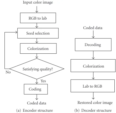
Figure 2shows the flow of the proposed colorization cod-ing and decodcod-ing algorithm. In the codcod-ing algorithm, as shown in Figure 2(a), the RGB color first converts to a luminance-chrominance color space. We have investigated many luminance-chrominance spaces such as YUV, YCbCr, and lαβ [12] under the same compression rate. Then, we found that the use of the CIELAB color space is the best in the quality of colorized images. Therefore, the CIELAB color space is used for expressing color image.
Second, color seed pixels are selected automatically. The selection method is described inSection 2.2. By blending the chrominance components of selected color seeds, all pixels with only luminance component can be colorized by the pro-posed colorization technique inSection 2.3. The color seed selection and colorization processes are continued until the colorized image satisfies a desired quality by changing the number of color seeds. Finally, the luminance component is coded by a standard lossy coding technique and information of color seeds, which is position and chrominance values, is stored as coded data.Section 2.4shows this coding scheme.
Figure 2(b) shows the decoding scheme. The decoding process is performed by backward tracing the coding algo-rithm. The luminance image component and the respective color seeds are decoded and coloring all pixels by the same
Input color image
RGB to lab
Seed selection
Colorization
Satisfying quality?
Coding Coded data
Yes No
(a) Encoder structure
Coded data
Decoding
Colorization
Lab to RGB
Restored color image (b) Decoder structure Figure2: Flowchart of the proposed algorithm.
colorization technique as the coding process. Then, the re-produced color image is in the CIELAB color space converted to the corresponding RGB output image.
2.2. Color seed selection
An input RGB color image is transformed into the CIELAB color space. In order to colorize the luminance image, color pixels from the original color image must be seeded on the luminance image domain. Although, in the general coloriza-tion scheme, a user selects the color seeds, in the image cod-ing scheme, the appropriate color seeds are selected automat-ically.
We have examined the following typical algorithms for selecting color seeds: (a) random selection, (b) selection from high luminance histogram, and (c) selection from box center at high pixel density in the CIELAB space. It is obvi-ous in (a) that a random setting of seeds results in the worst and huge seeds are required to colorize all pixels, because it is independent of image color distribution and seeds are sown on isolated regions. It is required to propagate many pixels by each color seed for reducing data size.
The case (b) constructs luminance histogram for all pix-els, in which seeds are selected from the set of pixels with the highest frequency. This method assumes that pixels in the same region have almost the same luminance. According to the assumption, a pixel with a high frequency on the lumi-nance histogram can belong to a large region on the image.
L∗
a∗
b∗
(a)
L∗
a∗
m-boxes
m
-bo
xes
m-bo
xes
(b)
L∗
a∗
(c)
Figure3: Seed selection algorithm from box center at high pixel density in the CIELAB space. (a) Color pixel distribution of original image. (b) Rectangular boxes (m=4). (c) Selected boxes and seeds (indicated as red circles).
(a) Leaves (b) Cat
Figure4: Examples of natural images.
the image gamut, respectively.Figure 3(c)shows the selected boxes with high pixel density and color seeds indicated by red circles. The location of each seed is not placed at the center of each cluster but placed at each body center in equally di-vided unit boxes. This method is much better than the other seed selection methods. We adopt theK-means clustering al-gorithm to place these seeds at the suitable positions in the CIELAB space.
The K-means algorithm partitions N data points into
K disjoint subsets Dk(k = 1, 2,. . .,K) containing Nk data points, so (N = N1+N2+· · ·+NK) as to minimize the sum-of-squares criterion,
J= K
k=1
n⊆Dk
Xn−µ k
2
, (1)
whereXnis a pixel belonging to a classDkandµkis the ge-ometric centroid of the pixels inDk. First, the initial seed pointsµseed(k) are assigned to the respectivekclasses. Then, coordinates of the centroid are recomputed after clustering and the seed points are renewed. The renewal is continued until no further change occurs in the centroid by iteration. Although theK-means is used as an unsupervised classifier by setting the initial seeds in random, the present algorithm uses this technique for relocating the initial seeds to the more reliable center of gravity in clusters. Finally, pixels near to
the converged centroids ofK-classes are determined as color seeds. If there are two or more pixels with the same color as the centroid, only one pixel is selected at random as a color seed. Since the restored image quality depends on the param-eterK, in our coding scheme, the parameterKis determined by a user as a quality parameter. However, it is possible to determineK automatically by the process of increasing the number ofK until the colorized image quality PSNRorg(k)
satisfies a certain desired quality PSNRdes.
2.3. Colorization
Colorization algorithm is essential in the colorization coding. We propose a colorization algorithm utilizing two properties of natural images.
The first property claims that if the spatial distance be-tween two arbitrary pixels in an image is close in the Eu-clidean distance, the chrominance distanceΔabis small. The chrominance distance Δab between colors (L1,a1,b1) and
(L2,a2,b2) is defined in CIELAB space as
Δab=a1−a2
2
+b1−b2
2
. (2)
We confirm the property using natural images. Figure 4
shows two examples of typical natural images. Figure 5(a)
100 80 60 40 20 0 Distance (pixel) 0 5 10 15 20 25 30 35 Δ ab Leaves Cat
(a) The relation between spatial distance and chrominance distance
30 25 20 15 10 5 0 ΔL∗ 0 5 10 15 20 25 30 35 40 Δ ab Leaves Cat
(b) The relation between luminance distance and chrominance distance Figure5: Properties of natural images.
y
x S1
S2
S3
d1(I,S1)
d1(I,S2)
d1(I,S3)
I & L∗ a∗ b∗ S1 S2 S3
d2(I,S1)
d2(I,S2)
d2(I,S3) I
L∗
a∗
b∗
a(I),b(I)
I
(a) NSD onx-yplane (b) NLD in CIELAB space (c) Estimated chroma ona∗-b∗plane Figure6: Geometric expression of the proposed colorization process.
average of the chrominance distanceΔabfor all pair of pixels inFigure 4. Horiuchi’s colorization algorithm in [8] was con-structed based on this property. It should be noted in both images that the chrominance distance increases as the spatial distance between pixels increases.
The second property is that pixels with similar luminance values have similar color. This property was used for solving colorization problem in Levin’s algorithm [7]. Figure 5(b)
shows the relation between the luminance distanceΔL∗and the average of the chrominance distance Δab for all pair of pixels in the images inFigure 4. The luminance distance
ΔL∗between colors (L1,a1,b1) and (L2,a2,b2) is defined in
CIELAB space as
ΔL∗=L1−L2
2
. (3)
Note thatΔabincreases withΔL∗.
LetI = (x,y) be a pixel in an input monochrome im-age, and let {Sp|Sp=(xp,yp)}Kp=1 be a set of color seeds, where K is the total number of the selected seeds, andSp is a coordinate of a color seed selected inSection 2.2. Each monochrome pixelIis transformed into the luminance com-ponentL(I). Each color seedSpis represented by the coordi-natesL(Sp),a(Sp),b(Sp) in the CIELAB color space. Then, we define two distances called NSD and NLD for expressing the above two properties as follows.
Normalized spatial distance (NSD)
The first distanced1(I,Sp)∈[0, 1] betweenI andSp is de-fined in the spatial domain as
d1
I,Sp
= I−Sp
2
width2+ height2, (4)
where width and height mean the horizontal size and vertical size of the monochrome image, respectively. Symbol·,·2
means the Euclidean distance.
Normalized luminance distance (NLD)
The second distanced2(I,Sp) ∈ [0, 1] betweenI andSp is defined in the luminance domain as
d2
I,Sp
= L(I)−L
Sp
100 . (5)
Then, we define a combined distanced(I,Sp) ∈ [0, 1] be-tween I andSp by the weighted sum of the both distances NSD and NLD as
dI,Sp
=αd1
I,Sp
r
+ (1−α)d2
I,Sp
r
, (6)
for colorization process and it is equivalent to the algorithm in [9]. The algorithm colorizes neighboring pixels with the same chrominance components, and it is impossible to ex-press texture regions. On the other hand, ifα=0 in (6), only the NLD, which is a luminance factor, is used for colorization process. The algorithm can colorize neighboring pixels with remarkably different colors, because pixels with the same lu-minance components in an image will be colorized with the same colors. Therefore, an appropriate blending parameterα is required. The optimum parameter value depends basically on the image contents. However, we found empirically that α=0.5 is useful for any images. Symbolr ∈R+indicates a
factor which can change the influence of the color seeds. Ac-cording to the investigation of property for natural images, the influence decreases rapidly as the distance increases, and the influence is nonlinear for the distance. This parameter was determined asr=5 empirically in our experiments.
We consider the chrominance componentsa(I) andb(I) of the target pixelIby blending the chrominance of seeds. As blending the seeds chrominance, we use the combined dis-tance. If the combined distanced(I,Sp) in (6) is small, the target pixelIshould be colorized with similar chrominance components of the seedSp. So, we transform the combined distanced(I,Sp) into a weightW(I,Sp)∈[0, 1] for blending chrominance of seeded color as
WI,Sp
= d
I,Sp
−1
pd
I,Sp
−1. (7)
Equation (7) shows that the weight for blending becomes large when the combined distance in (6) is small. Then, the color for the pixelIcan be represented byL(I),a(I), andb(I) by weighting chrominance of all seeds as follows:
L(I)=L(I),
a(I)= p
WI,Sp
aSp
,
b(I)= p
WI,Sp
bSp
,
(8)
where the luminance component L(I) maintains the lumi-nance value of the original image.
Figure 6illustrates the above algorithm. We use two dis-tances NSD and NLD in the (x,y) image plane and the CIELAB color space. The chrominance componentsa(I) and b(I) are determined based on the weighted distances on the luminance plane. Thus, the color value is determined based on the two properties with keeping the luminance value of the original image.
The proposed method determines the chrominance com-ponentsa(I) andb(I) by calculating the weighted average of them for color seeds in (8). If the directions of seeds’ vec-tors (a(Sp1),b(Sp1)) and (a(Sp2),b(Sp2)) are greatly different
in hue, the chroma (a(I),b(I)) may become different color from the seeds because (a(I),b(I)) is the weighted average vector. A solution to this irregular color problem is only to set appropriately seed pixels. The proposed algorithm can increase color seeds automatically until satisfying a desired quality PSNRdesby using theK-means algorithm. Since the
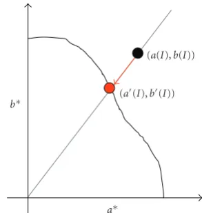
a∗
b∗
(a(I),b(I))
(a(I),b(I))
Figure7: Gamut mapping ona∗-b∗plane by clipping.
(a) Cherry tree
(b) Cat
25 20
15 10
5 0
Data (KB) 17
19 21 23 25 27 29 31
PSNR
(dB)
Proposed coding JPEG
(a) Cherry tree
7 6 5 4 3 2 1 0
Data (KB) 23
25 27 29 31 33 35
PSNR
(dB)
Proposed coding JPEG
(b) Cat
5 4
3 2
1
Data (KB) 20
23 26 29 32 35
PSNR
(dB)
Proposed coding JPEG
(c) Buckingham Figure9: Data size versus PSNR.
insufficient accuracy in PSNRorg(k) means that a lot of false
colors are generated, it can be solved by increasing the seed pixels until false color is improved. Concretely, we have many pixels with different chroma from the already seeded pixels in an image region where there are remarkably false colors. Then, we seed the region with the same chroma. In prac-tice, as shown inSection 2.2, because an initial seed in the
K-means algorithm is added to a rectangular box with high pixel density in the CIELAB space, there is high possibility of assigning a seed pixel to the false color region.
Then, the coordinate data of (L(I), a(I), andb(I)) are transformed into the standard RGB (sRGB) coordinate sys-tem for printing or displaying. The sRGB standard, origi-nally suggested by Ralf Kuron, is backward compatible and is based on a calibrated colorimetric RGB color space well suited to CRT monitors, television, scanners, digital cam-eras, and printing systems. We use the sRGB color space to reproduce a correct color with various devices. The trans-formed color coordinates determined color may exist outside of the sRGB gamut because L(I),a(I), andb(I) are deter-mined independently. Since we observe the colorized image on a printing device or display device, the color coordinates must exist within the sRGB gamut. For solving such a prob-lem, many gamut mapping algorithms have been proposed in the field of color science [13]. They are mostly designed to work in 2D L-C (Lightness-Chroma) planes. However, a big assumption in the general colorization scheme is to keep the luminance valueL∗of the original monochrome image. So, we consider a gamut mapping ona∗-b∗plane in this pa-per.Figure 7illustrates the gamut mapping used in our algo-rithm. We use a typical clipping algorithm in which a point out of gamut moves to the direction of origin with keeping the hue angle. The points within the gamut do not move to anywhere. InFigure 7, the estimated chrominance coor-dinates (a(I),b(I)) are mapped to the boundary of the sRGB gamut (a(I),b(I)). The gamut clipping has an advantage of keeping the entire color reproduction accuracy because the clipping algorithm does not change the color within the gamut [13]. This property is important in the color image coding, although color discontinuity can be caused around clipping part as an artifact.
2.4. Data coding
The above algorithms convert an input color image into lu-minance components and a small number of seed pixels. Ac-cording to the human visual perception, the luminance com-ponent is coded more precisely than the chrominance. In our algorithm, the luminanceLis coded by an orthogonal trans-form such as DCT and wavelet with high quality. The data of each seed pixel are coded as a four-dimensional vector which consists of the spatial coordinateI =(x,y) and the chromi-nance coordinate (a(I),b(I)). If 2 bytes are assigned for each element of the vector, it takes 8 bytse for each color seed. So, the total data become
Total data (byte)=coded (L) + 8K, (9)
whereKmeans the number of color seeds.
3. EXPERIMENTAL RESULTS
(a) Cherry tree (5 KB)
(b) Cat (2.5 KB)
(c) Buckingham (7 KB)
Figure10: Restored images under the same data size. Left: results by the proposed method. Right: results by the JPEG coding.
(a) (b)
Figure11: Restored images under the same data size 1.5 Kbyte. (a) results by the proposed method. (b) results by the JPEG 2000 coding.
example of image that includes large areas of high-frequency textures.Figure 8(c)is an example with large areas of uni-form colors.Figure 8(b)is an intermediate example. Our ex-periments used the JPEG coding for the luminance coding. The data size of the original image is 144 KB. We investigated the relation between data size and image quality by changing parameters. Note that the image quality changes greatly on the basis of the number of seeds.
The following peak signal-to-noise ratio (PSNR) [dB] was used as a measure of quality verification:
PSNR=10 log10 255
2
MSE
,
MSE= 1
3N
color N
i=1
xicolor−yicolor
2
,
where pixelsxicolor andycolori in an original image and a re-stored image have integer value from 0 to 255 at pixeliin a channel color={red, blue, and green}.Nmeans the total number of pixels.
Figure 9shows the relation between the PSNR value and the data size for the test images. The red and blue curves rep-resent the results by the proposed coding and the JPEG cod-ing, respectively. Comparison between red and blue curves suggests that the relative relationship between PSNR and data size looks similar for three images. The performance of the proposed method wins in the part of the high com-pression rate, while the performance of JPEG is higher than that of the proposed method in the part of low compres-sion rate. However, inFigure 9(b), the performance of JPEG is higher again in the part which is lower than 2 KB. This result means that the coding performance of the proposed method decreases when the number of color seeds is insuf-ficient, because the proposed method cannot perform an appropriate coloring by extremely small number of color seeds.
Images in Figures8(a)and8(b) include a lot of high-frequency components, and so many seeds are required for expressing texture parts. Nevertheless, a better performance than JPEG coding is obtained in such a region, as shown in Figures 9(a) and 9(b). Thus, the proposed coding gets better results in high-compression coding under the PSNR measure. For each image, almost 99% of the coded data oc-cupy the luminance component, and around 1% data is as-signed for chrominance components which correspond to seed pixels.
We show the restored images by the proposed coding method and JPEG coding method inFigure 10. For each pair of images, both images have the same data size which is high compression rate from 2% to 5% of the original data. Our experiments showed that terrible block noise appeared in the JPEG result, but it tends to have fewer blocky artifacts by the proposed method. However, the washed out color was rec-ognized by using the proposed algorithm. InFigure 10(c), the PSNR measure of the JPEG coding is better than that of the proposed coding. However, the texture of the road is de-stroyed by block noises for JPEG coding, and a fall of quality is recognized visually. In contrast, as for the proposed cod-ing, the color changes at the window by the lack of seeds, but the details of the original image are clearly restored.
Moreover, we compared the proposed algorithm with the JPEG2000. In this experiment, we used the JPEG2000 for the monochrome encoding in our algorithm. The rela-tionship between the proposed method and the JPEG2000 was almost the same as in Figure 9, though the total per-formance improved by using the JPEG2000.Figure 11shows images by the proposed coding method and JPEG2000 cod-ing method under the same data size 1.5 KB. The detailed inspection suggests that the image quality by the proposed method is better than JPEG2000. For instance, the restored image by JPEG2000 with high compression rate loses the de-tailed textures of cat’s hairs and trees inFigure 11, while the image by the proposed algorithm expresses the details more clearly.
4. CONCLUSIONS
This paper proposed a new color image coding algorithm based on the colorization technique. In our algorithm, at first, luminance component was separated from an input color image. Then, color pixels were selected as seeds from the input color image and colorize the luminance compo-nents. The color seed selection was continued until the col-orized image satisfies a desired quality. Finally, both the lumi-nance component and information of color seeds were stored as coded data. Thus, the proposed coding algorithm is essen-tially different from techniques based on signal transforms such as PCA and DCT.
The proposed algorithm has the following characteris-tics.
(1) Most bits are allocated to luminance coding, and only a small number of bits are used for chrominance coding. (2) The proposed method is effective for a high
compres-sion rate coding.
(3) Fewer blocky artifacts are recognized.
Since most of the coded data is luminance component, the data quantity of the luminance component is important for total performance. In our experiment, we used JPEG for luminance coding. We have to try to use other orthogonal transforms and investigate more suitable coding method for luminance component.
REFERENCES
[1] ISO/IEC FDIS 15444-1, “Core Coding System,” 2000. [2] ISO/IEC DIS 14495, “Generic coding of audio-visual objects”. [3] F. Pereira and T. Alpert, “MPEG-4 video subjective test proce-dures and results,”IEEE Transactions on Circuits and Systems for Video Technology, vol. 7, no. 1, pp. 32–51, 1997.
[4] ISO/IEC JTC1/SC29/WG11, “MPEG07/ M14493,” 2007. [5] ITU-T Rec.H.263, “Video coding for narrow
telecommunica-tion channels at<64kbit/s”.
[6] T. Welsh, M. Ashikhmin, and K. Mueller, “Transferring color to grayscale image,” inProceedings of the 29th ACM Interna-tional Conference on Computer Graphics and Interactive Tech-niques (SIGGRAPH ’02), vol. 20, pp. 277–280, San Antonio, Tex, USA, July 2002.
[7] A. Levin, D. Lischinski, and Y. Weiss, “Colorization using op-timization,”ACM Transactions on Graphics, vol. 23, no. 3, pp. 689–694, 2004.
[8] T. Horiuchi, “Estimation of color for gray-level image by prob-abilistic relaxation,” inProceedings of the 16th International Conference on Pattern Recognition (ICPR ’02), vol. 3, pp. 867– 870, Quebec, Canada, August 2002.
[9] T. Horiuchi and S. Hirano, “Colorization algorithm for grayscale image by propagating seed pixels,” inProceedings of the International Conference on Image Processing (ICIP ’03), vol. 1, pp. 457–460, Barcelona, Spain, September 2003. [10] T. Horiuchi, “Colorization algorithm using probabilistic
relax-ation,”Image and Vision Computing, vol. 22, no. 3, pp. 197– 202, 2004.
[12] D. L. Ruderman, T. W. Cronin, and C.-C. Chiao, “Statistics of cone responses to natural images: implications for visual coding,”Journal of the Optical Society of America A, vol. 15, no. 8, pp. 2036–2045, 1998.