IJSRSET173442| Received :08 July 2017 | Accepted : 18 July- 2017 | July-August-2017[(3)5: 152-156]
© 2017 IJSRSET | Volume 3 | Issue 5 | Print ISSN: 2395-1990 | Online ISSN : 2394-4099 Themed Section: Engineering and Technology
152
Performance Analysis of Helical Coil Heat Exchanger Using
Numerical Technique
Abhishek Nilay
1, Vishal Gupta
2, Samarjeet Bagri
31M.Tech. Scholar, Department of Mechanical Engineering, Radharaman Institute of Research and Technology,
Bhopal, India
2Principal, Diploma, Radharaman Engineering College, Bhopal, India 3Assistant Professor, Radharaman Group of Institutes, Bhopal, India
ABSTRACT
Helical coil heat exchangers are widely used in applications requiring large heat transfer area per unit volume. In present work, CFD simulation of helical coiled heat exchanger has been done. The diameter coil of heat exchanger has been varied along with mass flow rate. Water at 332 K has been considered at inlet. Parameters such as temperature drop, heat transfer rate, heat transfer coefficient and Nusselt number have been found out and compared for the geometric variations and variation in mass flow rate. It has been found out that temperature drop decreases for decrease in diameter of coil and also for increase in mass flow rate whereas heat transfer rate increases with increase in coil diameter and mass flow rate.
Keywords: Helical Coil, Temperature Drop, Heat Transfer Rate, Nusselt Number, Coil Diameter
I.
INTRODUCTION
The exchange of heat between one system to other is called heat transfer. It depends on system temperature and medium through which it is being transferred. The temperature difference between two fluids i.e. hot and cold fluid vary along the length of heat exchanger. In industries there are various applications of heat exchangers such as in food and chemical industry, power production industry etc.
II.
LITERATURE REVIW
Prabhanjan et al. [1] determined the advantage of using a helically coiled heat exchanger with respect to a straight tube heat exchanger for the purpose of heating liquids. Prabhanjan et al. [2] experimented heat transfer for a helically coiled heat exchanger.Kharat et al. [3] studied the heat transfer coefficient for concentric helical coil heat exchanger. Alimoradi [4] carried out investigation to find thermal effectiveness of shell and helically coiled tube heat exchangers. Ivan Di Piazza and Michele Ciofalo [5] obtained numerical results for turbulent flow and heat transfer in curved pipes which represent helically coiled heat exchangers. Deshmukh P.
et.al.[6]numerically found that helical coil tube type heat exchanger give highest heat transfer result among all counter flow helical coil heat exchangers. Pakdaman .M.F. et.al [7] experimentally investigated pressure drop characteristics of nanofluid flow inside vertical helically coiled tubes. C. E. KALB and J. D. SEADER [8] studied heat transfer in curved tubes. In present work helical coil heat exchangers have been modelled and their flow characteristics have been found out.
III.
GEOMETRIC MODELING
The geometry of helical coil heat exchanger has been made in CATIA V5 .The geometry has been imported to ANSYS 16.2 for the analysis.2
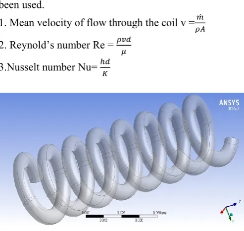
The geometric dimensions of the helical coil include the diameter of the tube (d), curvature diameter or pitch circle diameter of the coil (D) and coil pitch (p).
Table 1: Dimensional parameter of helical coil heat exchanger
S. No
Dimensional parameters
Dimensions
1 Average coil diameter
40 mm
2 Tube diameter 8 mm
10 mm
12 mm
3 Tube length 1000 mm
4 Working fluid Water
5 water temperature 332 K 6 wall temperature 293 K
7 Mass flow rate 0.005 Kg/s
0.05 Kg/s
0.02 Kg/s
For analytical calculations following equations have been used.
1. Mean velocity of flow through the coil v = ̇
2. Reynold’s number Re =
3.Nusselt number Nu=
Figure 1: 3D view of helical coil heat exchanger
IV.
MESHING AND MATERIAL PROPERTIES
After importing the geometry of helical coil heat exchanger into ANSYS CFD, the domain is divided into nodes and element which is also known as the meshing. The accuracy required for mesh can be specified by user. It can be tetrahedral or hexahedral depending upon available computational power. The number of elements and nodes are different for different geometry. For the meshing of 10mm diameter total number of element and nodes are 27133 and 34128 respectively.
Figure 2: 3D view of mesh of helical coil heat exchanger
The helical coil heat exchanger is made up of aluminium and water has been used as working fluid. Default properties of both have been considered for analysis.
V.
BOUNDARY CONDITIONS
Boundary conditions are needed to be specified for obtaining the output results. Proper selection of boundary condition leads to proper results and their improper selection lead to wrong solutions. Boundary conditions specified in Table 2 which have been used for present research work.
Table 2: Boundary Conditions.
Inlet Water with varying mass flow rate for different cases at temperature of 332K Outlet Pressure with value of 1 atm Turbulence Model K - ɛ
Convergence Criteria Absolute Number of Iteration 500
VI.
RESULTS AND DISCUSSION
Figure 3: Pressure variation for 8mm coil diameter for mass flow rate of 0.02 Kg/s.
Figure 4: Pressure variation for 10mm coil diameter for mass flow rate of 0.02 Kg/s.
From Figure 3 and 4, it is observed that pressure varies from inlet to outlet of heat exchangers. High pressure is observed near inlet of heat exchanger. It decreases gradually along the length of heat exchanger. The pressure difference is higher for thin coil diameter heat exchanger.
Figure 5: Temperature variation for 8 mm coil diameter for mass flow rate of 0.02 Kg/s.
Figure 6: Temperature variation for 10mm coil diameter for mass flow rate of 0.02 Kg/s.
From Figure 5and 6, it is seen that centre of the coil has fluid with highest temperature. Fluid layers near to the boundary are able to dissipate heat at a much higher rate so temperature is low near the periphery of tube. The temperature of working fluid reduces from inlet to outlet.
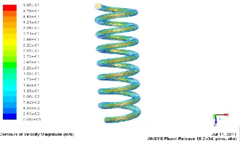
Figure 7: Velocity variation of fluid in 8 mm coil diameter for mass flow rates of 0.02Kg/s.
Figure 6: Velocity variation of fluid in 10 mm coil diameter for mass flow rates of 0.02Kg/s.
thick diameter coil. Higher velocity is found out in the centre of coil due to boundary layer flow, the flow velocity is low near outer periphery of heat exchanger.
Figure 9: Variation in temperature drop with mass flow rate at different diameter.
Fig.9 shows the variation in temperature drop at different mass flow rates of 0.005 Kg/s, 0.02Kg/s and 0.05Kg/s for specified coil diameters. The figure shows high temperature drop for thick diameter coil and the temperature drop decreases with decrease in diameter of coil for same mass flow rate. Similar trend is seen at all the mass flow rates. For a specified coil diameter, the temperature drop decreases with increase in mass flow rate. The reason for this can be that the fluid is not able to absorb much heat at higher velocity before leaving out of the heat exchanger.
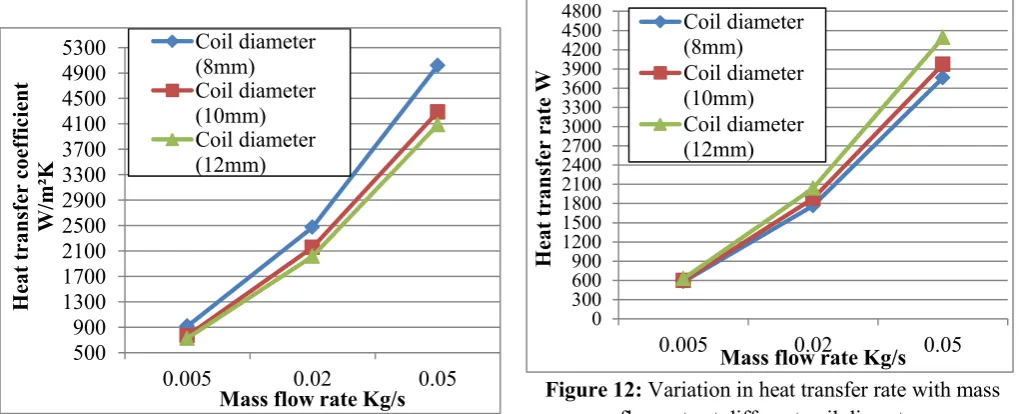
Figure 10: Variation in heat transfer coefficient with mass flow rate at different diameter of coil.
Fig 10 shows variation in heat transfer coefficient with variation in diameter of coil. Increase in coil diameter leads to deterioration in heat transfer coefficient. Maximum heat transfer coefficient is obtained for 8 mm diameter and minimum for 12 mm diameter. For same diameter coil, as mass flow rate is increased, the heat transfer coefficient increases.
Figure 11: Variation in Nusselt number with mass flow rate for different coil diameter.
Variation in Nusselt number at different mass flow rates (0.005Kg/s, 0.02Kg/s and 0.05Kg/s) for various diameters is shown in Fig 11. It is seen that the Nusselt number increases with increase in coil diameter for same mass flow rate. The minimum value of Nusselt number is obtained for 8 mm diameter coil while maximum for 12 mm diameter coil. As the mass flow rate increases, Nusselt number increases.
Figure 12: Variation in heat transfer rate with mass flow rate at different coil diameter.
Fig 12 implies that heat transfer rate depends on diameter of heat exchanger. Increase in diameter causes 12 15 18 21 24 27 30 33
0.005 0.02 0.05
T em perat ure dif fe re nc e °C
Mass flow rate Kg/s
Coil diameter (8mm)
Coil diameter (10mm)
Coil diameter (12mm)
500 900 1300 1700 2100 2500 2900 3300 3700 4100 4500 4900 5300
0.005 0.02 0.05
H eat t ransf er coe ff ici ent W/ m ²K
Mass flow rate Kg/s
Coil diameter (8mm) Coil diameter (10mm) Coil diameter (12mm) 8 13 18 23 28 33 38 43 48 53 58 63 68 73 78 83
0.005 0.02 0.05
Nuss el t num be r
Mass flow rate Kg/s
Coil diameter (8mm) Coil diameter (10mm) Coil diameter (12mm) 0 300 600 900 1200 1500 1800 2100 2400 2700 3000 3300 3600 3900 4200 4500 4800
0.005 0.02 0.05
H eat t ransf er rat e W
Mass flow rate Kg/s
increase in heat transfer rate of a helically coiled heat exchanger because area for heat dissipation increases. According to the figure maximum heat transfer rate obtained for 12 mm diameter and minimum for 8 mm diameter coil. This is in agreement with analytical calculations.
VII.
CONCLUSION
Helical coil heat exchanger have better heat transfer rate as compared to straight tube heat exchanger. On increasing the mass flow rate, temperature difference of inlet and outlet fluid decreases, whereas on increasing the diameter of coil for same mass flow rate temperature difference increases. So to enhance heat transfer rate, larger coil diameter heat exchangers can be used. Nusselt number, temperature difference of fuild and heat transfer rate increases with increase in coil diameter of helical coil heat exchanger.
VIII.
REFERENCES
[1]. Prabhanjan .D.G, Rennie .T.J, Raghavan .G.S.V, 2002Comparison of Heat Transfer Rates between a Straight Tube Heat Exchanger and a Helically Coiled Heat Exchanger D. 29, Pp 185-191.
[2]. Prabhanjan .D.G, Rennie .T.J, Raghavan .G.S.V, 2004 Natural Convection Heat Transfer from Helical Coiled Tubes. 43, Pp 359-365.
[3]. Kharat.R, Bhardwaj.N, Jha.R.S, 2009 Development of heat transfer coefficient correlation for concentric helical coil heat exchanger. 48,Pp 2300-2308.
[4]. Alimoradi .A, 2017. Study of thermal effectiveness and its relation with NTU in shell and helically coiled tube heat exchangers. 9, Pp 100-107.
[5]. Pizza.I.D and Ciofalo.m, 2010. Numerical Prediction of Turbulent flow and heat transfer in helically coiled pipes. 49 Pp 653-663.
[6]. Deshmukh .P, Patil V.D, Devakant.B, 2016. CFD Analysis of Heat Transfer In Helical Coil Tube In Tube Heat Exchanger. 3 Pp 01-08.
[7]. Pakdaman.M.F, Behabadi.M.A.A, Razi.P, 2013. An empirical study on the pressure drop characteristics of nanofluid flow inside helically coiled tube. 65. Pp 206-213.