IJIRT 147620
INTERNATIONAL JO URNAL OF INNOVATIVE RESEARCH IN TECHNOLOGY256
CFD Analysis on Shell and Coiled Tube Heat Exchanger
for Heat Transfer Augmentation Due to Air Bubbles
Injection
Prof. O.P Shukla
1, Bablu Kumar Yadav
21
Corporate Institute of Science and Technology, Professor, RGPV Bhopal, MP, INDIA
2
Corporate Institute of Science and Technology, Research Scholar, RGPV Bhopal, MP, INDIA
Abstract- In this work, attempts are made to increase the number of thermal units (NTU) and performance in a horizontal shell and coiled tube heat exchanger via air bubble injection into the shell side of heat exchanger. Besides, exergy loss due to air bubble injection is investigated. Indeed, air bubble injection and bubbles mobility (because of buoyancy force) can intensify the NTU and exergy loss by mixing the thermal boundary layer and increasing the turbulence level of the fluid flow. Air bubbles were injected inside the heat exchanger via a special method and at new different conditions in this work.If an air flow is injected into a liquid fluid, many ambulant air bubbles are formed inside the fluid. Air bubbles move inside the liquid fluid because of the buoyancy force, and the mobility of these air bubbles makes sizable commixture and turbulence inside the fluid.
This mechanism was employed to enhance the heat transfer rate of a horizontal S hell and Helical tube heat exchanger. The main scope of the present work is to clarify the effect of air bubble injection on the heat transfer rate and effectiveness through a horizontal S hell and Helical tube heat exchanger. However it can be used in any other type of heat exchanger. Especially, this method can be expanded as a promising heat transfer improvement technique in automotive cooling system, for instance in radiator which contains of water or other liquid fluid. The ANS YS FLUENT 14.5 has been used for numerical analysis using multiphase- Eulerian and energy. The k-ϵ standard turbulent model has been used. The graph has been plotted for Nusselt number, NTU, effectiveness and overall heat transfer for different diameter of air bubbles. It has been observed that the 0.7mm diameter of air bubbles has best heat transfer.
Index Terms- S hell and helical coil heat exchanger, Air bubbles injection, NTU, Nusselt number, Effectiveness, Heat transfer coefficient, CFD.
I. INTRODUCTION
Heat transfer is defined as the movement of energy due to a temperature difference. It is characterized by the following three mechanisms:
Conduction. Heat conduction takes place through different mechanisms in different media. It can be theoretically explained to take place through collisions of the molecules in a gas, through oscillations of each molecule in a “cage” formed by its nearest neighbor’s in a fluid, and by the electrons carrying heat in metals or by molecular motion in other solids. Typical for heat conduction is that the heat flux is proportional to the temperature gradient.
Convection. Heat convection takes place through the net displacement of a fluid, which translates the heat content in a fluid through the fluid's own velocity. The term convection is also used for the heat dissipation from a solid surface to a fluid, where the heat transfer coefficient and the temperature difference across a fictive film is used to describe the flux. Both descriptions are included in the Heat Transfer Module.
Radiation. Heat transfer by radiation takes place through the transport of photons. These photons can be absorbed or reflected on solid surfaces. The Heat Transfer Module includes Surface-to-surface radiation, which accounts for effects of shading and reflections between radiating surfaces. It also includes surface-to-ambient radiation where the ambient radiation can be fixed or given by an arbitrary function.
IJIRT 147620
INTERNATIONAL JO URNAL OF INNOVATIVE RESEARCH IN TECHNOLOGY257
separated by a solid wall to prevent mixing or may bein direct contact. Heat exchangers can improve a system’s energy efficiency by transferring heat from systems where it is not needed to other systems where it can be usefully used.
Heat Exchangers are available in many types of construction, each with its advantages and limitations. The main heat exchanger types are: Shell & Tube – The most common heat exchanger design type consists of a parallel arrangement of tubes in a shell. One fluid flows through the tubes and the other fluid flows through the shell over the tubes. Tubes may be arranged in the shell to allow for parallel flow, counter flow, cross flow, or both. Heat exchangers may also be described as having tube layouts in single pass, multi-pass, or U-tube arrangements. Due to its tubular construction, this type of exchanger can handle large pressures. The exchanger may have one or two heads on the shell and multiple inlet, outlet, vent, and drain nozzles.
Heat Transfer Enhancement
Heat transfer enhancement techniques can be found in different engineering applications, such as solar energy systems, thermal control, electronics cooling, nuclear reactors, heat exchangers, automotive cooling, refrigeration, chemical process, etc. They are classified as passive methods and active methods. In the first method, no direct application of external power is required, whereas in the second method an external power source is necessary. The effectiveness of heat transfer enhancement techniques is strongly related to the heat transfer mechanisms. This can be due to single-phase free convection and dispersed-flow film boiling. Plate fins, nanofluids, and porous insertions can be considered as examples of passive techniques, while magnetic fields, induced vibrations, and rotations are examples of active techniques.
Air bubble injection
Injecting air bubbles in a fluid flow path is one of the promising technique to increase the turbulence in the flow. The air can either be injected at the entrance of the fluid in the channel or tube so that it can properly mixed before entering or throughout the channel or tube so that there would be a reduction in the skin friction. This also increases the turbulence and thus enhances the different parameters such as heat transfer rate, efficiency etc. Studies have been done
on different conditions with air bubble injection and results show a considerable enhancement in the different parameters such as heat transfer performance, turbulence etc.
Helical Coil Heat Exchanger
The helical coil heat exchangers are a compact shell and tube design consisting of several layers of coiled tubes within a closed shell.
Helical coils are widely used in applications such as heat recovery systems, chemical processing, food processing, nuclear reactors, and high temperature gas cooling reactors. Helical coils are characterized by their compactness and high heat transfer coefficient. When fluid flows through a helically coiled tube, the curvature of the coil induces centrifugal force, causing the development of the secondary flow. This secondary flow enhances fluid mixing and thus heat transfer. Fluid flow in a helical tube is characterized by the Dean number. The Dean number, D, is a measure of the geometric average of inertial and centrifugal forces to the viscous force ratio, and thus is a measure of a magnitude of the secondary flow. For laminar flow and small pipe to coil radius aspect ratio r/R, frictional loss in a curved tube may be represented as a function of the Dean number. One of the most frequent uses of helically coiled tubes is in the shell and coiled tube heat exchangers
Figure 1 Helical coil Shell and tube heat exchanger
II. LITERATURE REVIEW
IJIRT 147620
INTERNATIONAL JO URNAL OF INNOVATIVE RESEARCH IN TECHNOLOGY258
date. The literature in enhanced heat transfer isgrowing faster than that for the engineering literature as a whole. At least fifteen percent of the heat transfer literature is directed towards the techniques of heat transfer augmentation now. In the past decade, several studies on passive and active techniques of heat transfer augmentation have been reported. Literature review on active and passive techniques of heat transfer augmentation is given in the following sections.
Previous work
Khorasani et al. (2017) studied experimentally the effects of air bubble injection on the performance of a horizontal helical shell and coiled tube heat exchanger. The variations of number of thermal units (NTU), exergy loss and effectiveness due to the air bubbles injection with different air flow rates are evaluated. A new procedure for injecting the air bubbles into the shell side flow of the heat exchanger is proposed. The results exhibited a significant increase in the effectiveness and NTU of the h eat exchanger as the air bubbles were injected. It is suggested that the disturbance and perhaps the turbulence intensity of the shell side flow are increased due to the motion of air bubbles resulting in an increment in the value of NTU and exergy loss. In addition, the mixing effect of the bubbles and the interaction with the thermal boundary layer can increase the velocity (hence the Reynolds number) of the shell side flow.
Andrew et al. (2016) studied due to their compact design, ease of manufacture and enhanced heat transfer and fluid mixing properties, helically coiled tubes are widely used in a variety of industries and applications.
Dizaji et al. (2015) studied experimentally the effects of flow, thermodynamic and geometrical characteristics on exergy loss in vertical shell and coiled tubes heat exchangers. Pressure drop and heat transfer characteristics in shell and coiled tube heat exchangers have been widely studied in the resent years. However, the effects of flow, thermodynamic and geometrical parameters on energetic characteristics have not been explicitly and experimentally studied. Hence, the main scope of the present work is to clarify the effect of shell and coil side flow rates, inlet temperatures, coil pitch and coil diameter on exergy loss in shell and coiled tube heat
exchangers. Both of the total exergy loss and dimensionless exergy loss are studied.
Samaroo et al. (2014) performed an experiment on the turbulent flow characteristics in an annulus under air bubble injection and sub cooled flow boiling conditions with water as the working fluid. Their findings indicated that, in the laminar flow case, the coalescence of two bubbles successively injected is seen, and in turbulent flow, the bubble departure frequency increases and no coalescence are observed. Saffari et al. (2013) investigated the effect of bubble injection on pressure drop reduction in helical coil. The experimental results indicated that the maximum reduction of friction drag is 25%, which occurs at low Reynolds numbers.
J. Koo et al.(2000): Investigated the nanoparticle collision and deposition in the surface wall with help of micro channel heat sink. Which has the dimension of 1cmx100micometerx300micrometer, water-CuO and CuO-ethylin glycol Nano fluids are through the micro channel heat sink? They are investigated the base fluid should possess high prandtl number, and get enhanced heat transfer rate by minimize particle-particle and particle-wall collision. Viscous dissipation effect is important of narrow channel, because Nusselt number high for high aspect ratio channel.
L.B. Mapa et al.(1997): Measured enhanced thermal conductivity of Cu-water Nano fluid using shell and tube heat exchanger. Where the dimension of heat exchanger is 240x24x0.25mm, using 37 tubes. The outcome of this analysis is rate of heat transfer is increases with increasing flow rate and also its concentration. By nanoparticle dispersed into de-ionized base fluid a better enhancement is achieved Summary of literature review
As we know Shell and tube heat exchanger is one of the non-contact type heat exchanger widely being used in many process industries. About 65% of the total heat exchanger used is shell and tube heat exchanger and is widely being used in power plants, food processing industries, chemical industries, petro-chemical industries etc.
IJIRT 147620
INTERNATIONAL JO URNAL OF INNOVATIVE RESEARCH IN TECHNOLOGY259
Injecting air bubbles in a fluid flow path is one of thepromising techniques to increase the turbulence in the flow. The air can either be injected at the entrance of the fluid in the channel or tube so that it can properly mixed before entering or throughout the channel or tube so that there would be a reduction in the skin friction. This also increases the turbulence and thus enhances the different parameters such as h eat transfer rate, efficiency etc. Studies have been done on different conditions with air bubble injection and results show a considerable enhancement in the different parameters such as heat transfer performance, turbulence etc.
III.METHODOLOGY
After studying the basic steps in CFD to be followed to analysis the flow inside a duct. Now we can start the analysis of the solar air heater with actual data .following three steps are required to run the simulation-
1- Geometry modelling, 2- Meshing, 3- Name Selection, 4- Type of solver, 5- Physical model, 6- Material property, 7- Boundary condition.
Geometry setup
The ANSYS Design Modeller provides the following approaches for model generation: Creating a surface model within ANSYS Design Modeller. The heat exchanger setup the geometry of helically coiled tube shell and tube heat exchanger performing the simulation study is taken form one of the research scholar’s Khorasani et.al. (2017) paper with exact dimension .The part of model was designed in ANSYS (Fluent) workbench14.5 software. The geometric dimension of the shell and tube heat exchanger is shown in the Table 6.1.
Table .1 Dimensions of the shell and coiled tube
T ube L(m m)
t(mm )
l(mm )
Din( mm)
2Rin( mm)
2r(m m)
P( m m) Shell 410 3 --- --- --- 152.
4 ---- Coile
d T ube
3800 1.44 390( bco)
4.4 114 ---- 33
Figure 2 Geometry of Shell and helical coil heat exchanger.
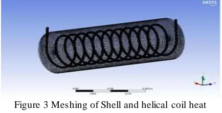
Meshing
The total Node is generated 220114 & Total No. of Elements is 47234. Mesh contains mixed cells per unit area (hexahedral cells) having triangular and quadrilateral faces at the boundaries.
Figure 3 Meshing of Shell and helical coil heat exchanger.
Type of Solver
After mesh generation defined the following setup in the ANSYS fluent.
Problem Type- 3D, Steady State Type of Solver- Pressure-based solver
Physical Model
Viscous: k- ε (epsilon) two equation turbulence model.
Material Property
Table 2 Material properties which are used in analysis.
Parameter Air Water Aluminium
Density (Kg/m3) 1.225 998.2 2719
Thermal Conductivity (W/m-k )
0.0242 0.6 202.4
Specific heat
(J/kg-k) 1006.43 4182 871
Viscosity
(kg/m-s) 1.789 0.001003 --
Boundary Conditions
Table 3: Boundary condition of different parameters
Name
M ass flow
rate (Kg/s) Velocity (m/s)
Temperature (K)
Cold water
inlet 0.0831 0.658 296.15
Hot water
inlet 0.0166 1.096 316.15
IJIRT 147620
INTERNATIONAL JO URNAL OF INNOVATIVE RESEARCH IN TECHNOLOGY260
IV. RESULTS AND DISCUSSIONSFor viewing and interpretation of Result. The result can be viewed in various formats, graph, value, animation etc. The data collected using ANSYS FLUENT 14.5 included the temperature distribution, pressure distribution and airflow velocity at all node points in the model. We can see the following result-
Figure 4 Static temperature contour of the helical
coil heat exchanger for 0.05mm dia. air bubbles.Figure 5 Velocity magnitude contour of the helical
coil heat exchanger for 0.05mm dia. air bubbles.Figure 6 Air bubble particle velocity contour of the
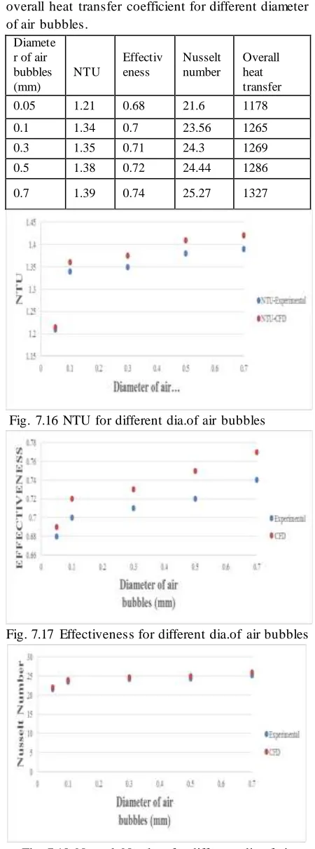
helical coil heat exchanger for 0.05mm dia. air bubblesTable 4 NTU, effectiveness and Nusselt number and overall heat transfer coefficient for different diameter of air bubbles.
Diamete r of air bubbles (mm)
NTU
Effectiv eness
Nusselt number
Overall heat transfer
0.05 1.21 0.68 21.6 1178
0.1 1.34 0.7 23.56 1265
0.3 1.35 0.71 24.3 1269
0.5 1.38 0.72 24.44 1286
0.7 1.39 0.74 25.27 1327
Fig. 7.16 NTU for different dia.of air bubbles
Fig. 7.17 Effectiveness for different dia.of air bubbles
IJIRT 147620
INTERNATIONAL JO URNAL OF INNOVATIVE RESEARCH IN TECHNOLOGY261
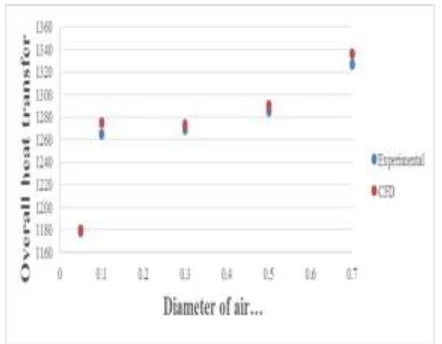
Fig. 7.19 Overall heat transfer for different dia.of airbubbles
V. CONCLUSIONS
In this analysis, the effect of air bubbles diameter on the effectiveness, NTU and Nusselt number of shell and helical coil heat exchanger has been investigated using CFD analysis. Based on the results, obtained by the CFD and mathematical calculations it is found that;
The percentage variation observed between experimental result and simulation result is 2.15 – 4.15%.
From the above analysis it has been observed that at 0.05, 0.1, 0.3, 0.5and 0.7 mm diameter of air bubbles Nusselt number increase.
From Table 4 it has been observed that NTU at 0.05mm to 0.1 mm increase thereafter.
Table 4 it is concluded that 0.7 mm diameter of air bubbles is better than other ones.
REFERENCES
[1] Ahmadzadehtalatapeh M, Yau YH. Energy conservation potential of heat pipe heat exchanger: Exprimental study and predictions. International Journal of Engineering Tran¬section B: Applications. 2012 Aug; 25(3):193–200.
[2] Kahrom M, Haghparast P, Javadi SM. Optimization of heat transferenhancement of flat plate based on pereto genetic algorithm. International Journal of Engineering, Transaction A: Basics. 2010 Apr; 23(2):177–90.
[3] Lee HS. Thermal design. John Wiley and Sons; 2010.
[4] Li H, Kottke V. Analysis of local shell side heat and mass transfer in shell and tube heat exchanger with disc and doughnut baffles. International Journal of Heat and Mass Transfer. 1999 Sep; 42(18):3509–21.
[5] Peng B, Wang QW, Zhang C, Xie GN, Luo LQ Chen QY, Zeng M. An experimental study of shell and tube heat ex¬changers with continuous helical baffles. Journal of Heat Transfer. 2007 Jan; 129(10):1425– 31.
[6] Jamsidi N, Farhadi M, Ganji DD, Sedighi K. Experimental analysis of heat transfer enhancement in a shell and tube heat exchanger. Applied Thermal Engineering. 2013 Mar; 51(1– 2):644–52.
[7] Farajollahi B, Etemad S, Hojjat M. Heat transfer of nanoflu¬ids in shell and tube heat exchanger. International Journal of Heat and Mass Transfer. 2010 Jan; 53(1–3):12–17.