1509 |
P a g e
DESIGN AND PARAMETRIC ANALYSIS OF
TRIANGULAR MICROSTRIP ANTENNA LOADED
WITH DIELECTRIC SUPERSTRATE
Sandeep Sharma
1, Dr.M.R.Tripathy
21,2
Department of Electronics and Communication
1
Bhagwan parshuram Institute of Technology(GGSIPU) Delhi (India)
2
Amity school of Engg. And Technology, Noida, U.P (India)
ABSTRACT
In this paper, the effect of a dielectric superstrate on the gain and resonant frequency of a triangular microstrip
antenna has been studied. The proper choice of thickness of superstrate and superstrate layer result
insignificant improvement in gain. The improvement in reflection coefficient is also shown. The results obtained
shows a shift in resonant frequency by introducing the superstrate of suitable thickness and material.
Keywords:
Antenna, Resonant Frequency, Triangular Microstip Antenna, Superstrate.
I. INTRODUCTION
The attractive features of mirostrip antennas [1] such as light weight, low profile, manufacturing ease and
compatibility with integrated circuit technology have recently demanded greater investigation of their
performance and applications. However mirostrip antennas have narrow bandwidth and can only operate
effectively in vicinity of resonant frequency which limit its wider application. Large numbers of investigations
have been conducted on triangular patch microstrip antenna which shows the remarkable advantages of
equilateral triangular geometry[2].The dielectric superstrate loaded equilateral triangular patch antenna using
spectral domain technique has been studied[3]. Dahele and Lee[4] concluded that if the side length of the
triangular patch is replaced by its effective value while leaving the relative permittivity unchanged, good
agreement between theory and experiment is obtained. Garg and Long[5] also arrived at the same results.
This paper represents the experimental and theoretical study of triangular microstirp patch antenna with
dielectric superstrate and how loading are used to accurately estimate the effect of a superstrate on gain
parameter and resonant frequencies. The computed results for different radome dimensions are compared with
the experimental values.
II.
THEORETICAL
FORMULAS
As per the cavity model analysis by Helszajn[6], the general formula for the resonant frequencies of TMmn
modes obtained for triangular patch antenna can be given as
1510 |
P a g e
There are two suggestions for accounting for nonperfect magnetic wall effects. The sidelength a should be
replaced by the effective value
= (2)
BB[7] proposed that alongwith the effective value of , effective value of ϵr should be replaced as
(3)
Although in the cavity modal of the equilateral triangular patch, the sidelength a will be replaced by its effective
value ae but ϵr should not be replaced ϵe .
2.1 Input Impedance of coaxial fed Antenna
The input impedance of coaxial fed antenna where the feed point is located at a distance d from vertex of
antenna is given as
(4)
Where δeff is effective loss tangent .If the frequency is adjusted such that the loss of surface wave is negligible
then it is given by
(5)
Where Pr, Pd and Pc are the radiation, dielectric and copper losses respectively and 2WE is energy stored in cavity.
1511 |
P a g e
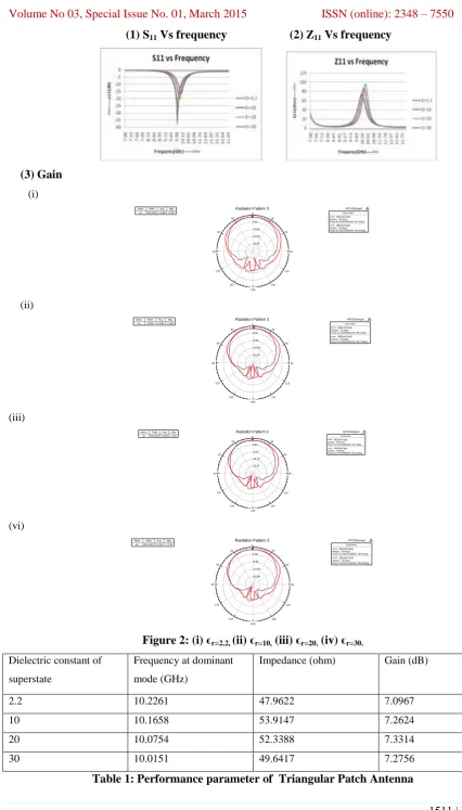
(1) S
11Vs frequency (2)
Z
11Vs frequency
(3)
Gain
(i) -30.00 -20.00 -10.00 0.00 90 60 30 0 -30 -60 -90 -120 -150 -180 150 120 HFSSDesign1Radiation Pattern 3 ANSOFT
m1 Curve Info
dB(GainTotal) Setup1 : Sw eep1 Freq='10.22613065GHz' Phi='0deg'
dB(GainTotal) Setup1 : Sw eep1 Freq='10.22613065GHz' Phi='90deg' Name Theta Ang Mag
m1 360.0000 -0.00007.0967
(ii) -22.00 -14.00 -6.00 2.00 90 60 30 0 -30 -60 -90 -120 -150 -180 150 120 HFSSDesign1
Radiation Pattern 3 ANSOFT
m1 Curve Info
dB(GainTotal) Setup1 : Sw eep1 Freq='10.16582915GHz' Phi='0deg'
dB(GainTotal) Setup1 : Sw eep1 Freq='10.16582915GHz' Phi='90deg' Name Theta Ang Mag
m1 2.00002.00007.2624
(iii) -22.00 -14.00 -6.00 2.00 90 60 30 0 -30 -60 -90 -120 -150 -180 150 120 HFSSDesign1
Radiation Pattern 3 ANSOFT
m1 Curve Info
dB(GainTotal) Setup1 : Sw eep1 Freq='10.07537688GHz' Phi='0deg'
dB(GainTotal) Setup1 : Sw eep1 Freq='10.07537688GHz' Phi='90deg' Name Theta Ang Mag
m1 360.0000 -0.00007.3314
(vi) -22.00 -14.00 -6.00 2.00 90 60 30 0 -30 -60 -90 -120 -150 -180 150 120 HFSSDesign1
Radiation Pattern 3 ANSOFT
m1 Curve Info
dB(GainTotal) Setup1 : Sw eep1 Freq='10.01507538GHz' Phi='0deg'
dB(GainTotal) Setup1 : Sw eep1 Freq='10.01507538GHz' Phi='90deg' Name Theta Ang Mag
m1 360.0000 -0.00007.2756
Figure 2: (i) ϵ
r=2.2,(ii) ϵ
r=10,(iii) ϵ
r=20,(iv) ϵ
r=30.Dielectric constant of
superstate
Frequency at dominant
mode (GHz)
Impedance (ohm) Gain (dB)
2.2 10.2261 47.9622 7.0967
10 10.1658 53.9147 7.2624
20 10.0754 52.3388 7.3314
30 10.0151 49.6417 7.2756
1512 |
P a g e
IV
.
CONCLUSION
AND
DISCUSSION
In conclusion the variation of the gain with superstrates of different dielectric constant have been shown. These
results appear to informative during the implementation and design of the microstrip antenna. It is found that as
the permittivity of material increases, compactness increases.
REFERENCES
[1] A. Bhattacharyya, and R. Garg, Analysis of Circular patch Microstrip Antenna Cavity Model. Arch. Elek.
Ubertragung 39, 317–325 (2000)
[2] Jia-Sheng Hong and M.J Lancaster, “Theory and experiment of dual-mode microstrip triangular patch
resonator and filter” IEEE Trans.Microwave Theory Tech., vol. 52, No-4 pp.1237-1243, Apr. 2004
[3] H.R.Hassani and D.mirshekar Sakyal, “Analysis of triangular patch antenna including radome effect”,IEEE
Proceeding H, vol.139, no 3, pp.251-256,Jun 1992
[4] K. F. Lee,and J. S. Dahele, “On the resonant frequencies of triangular patch antenna”, IEEE transactions
on antennas and propagation, vol. 35, pp. 100-101, Aug. 1987
[5] R.Garg and S.A.Long,”An improved formula for the resonant frequencies of triangular patch antenna”
control” vol. 36, pp. 570, Aug. 1988
[6] J.Helszajn and D.S.James,”Planer triangular resonator with magnetic walls” IEEE Trans.Microwave Theory
Tech., vol. MTT-26, No-2, pp.95-100, 1978.
[7] J. Bahl, and P. Bhartia, Microstrip Antennas, Chap. 4 & 5. (Artech House, Dedham)
[8] I.Wolff and N.Knoppik,“Rectangular and circular microstrip disk capacitors and resonators”,IEEE
Trans.Microwave Theory Tech., vol. MTT-22, pp. 857-864, Oct. 1974
[9] J.S. Dahele, S.Mem and K.F.Lee “Theory and experiments on microstrip antennas with airgaps” Proc. Inst.
Elect.Eng. vol. 132,No-7,pp.455-460, Dec. 1985
[10] Debatosh Guha, Senior Member, IEEE “Resonant frequency of circular microstrip antenna with and
without airgaps”, IEEE transactions on antennas and propagation, vol. 49, no. 1, January 2001
[11] J. R. James and P. S. Hall (Eds.), Handbook of Microstrip Antennas (Peter Peregrinus, London, UK, 1989).
[12] Debatosh Guha, Senior Member, IEEE, Comment on “A new model for calculating the impedance of
coax-fed circular microstrip antenna with and without airgaps” IEEE Trans. Antennas Propagat, vol.
48pp.1010-1011, June 2002
[13] W.C.Chew and J.A.Kong ,“Effect of fringing field on the capacitance of circular microstrip disk”,IEEE
Trans.Microwave Theory Tech., vol. MTT-28, pp. 98-104, Feb. 1980
[14] T. Itoh and R. Mittra “Analysis of microstrip disk Resonantor ”, Arch. Eleck. Ubertragung, vol. 27 , no. 11,
pp. 456-458, 1973
[15]S.S.Pattnaik,O.P.Bajpai,S.V.R.S.Gollapudi,SwapnaDevi"Bacterial foraging technique to calculate resonant
frequency of rectangular microstrip antenna," International Journal of RF and computer aided Engineering
DOI 10.1002/mmce
[16]C.M.Montiel, L.Fun and K. Chang “a noval active antenna with self mixing and wideband varactor tuning
capabilities for communication and vehicle identification applications”, IEEE transactions Microwave
1513 |
P a g e
[17] K. F. Lee, K. Y. Ho and J. S. Dahele, “Circular disk microstrip antenna an with airgap”, IEEE
transactions on antennas and propagation, vol. 32, pp. 880-884, Aug. 1984
[18] R.A.Flyant, L.Fun and K. Chang “Low cost and compact active integrated antenna transceiver for system
application.”, IEEE transactions Microwave theory Tech, vol. 44, pp. 1642-1649, Oct. 1996
[19] H. A. Wheeler, “A simple formula for the capacitance of a disc on dielectric on a plane”, IEEE