Themed Section: Science and Technology
A Study on the Analysis and Design of Commercial Building (G+9) Using
Response Spectrum Method in ETABS
Vanaparthi Paparao*1, Syed Rizwan*2, Dr. C. Rama Chandrudu*3
1M.Tech Student, St.Mark Educational Institute Society Group of Institutions, Anantapur, Andhra Pradesh,
India
2,3Assistant Professor and Professor, Civil Engineering Department , Chiranjeevi Reddy Institute of Engineering
& Technology, Anantapur, Andhra Pradesh, India
ABSTRACT
Humans has started rising higher due to lace in horizontal space, Building taller structures has become a common trend. But as this vertical limit is pushed the risk factor increase. Skyscraper has to be analyzed for various loads to provide safety. Behaviour of a structure is most critical during earthquake thus it is important to analyze a structure for seismic resistance. Earthquake is an unpredictable hazard having power to bring a high raised structure to ground. Thus it is important to analysis a structure for seismic force. Seismic coefficient method can be used to analyze small and medium height structure up to 40m. It is a simple method of analysis and required less calculation. The behaviour of a structure depends critically on overall shape, size and geometry. A study on the behaviour of RC building during earthquake is done to understand different in seismic loading and difference in behavior due to different shape. A 9 storey building with height of each floor 3m is analyzed by seismic coefficient method with the help of ETABS software. ETABS may provide an easy, efficient and accurate way to analyze a structure. The analysis is done as per IS 1893:2002 (Part-1). Estimation of response such as; lateral forces, base shear, storey drift, storey shear etc. is carried out for all the different shaped RC buildings and Compared based on response given by different shaped building.
Keywords : ETABS, RC building, Autocad, Staad, Etabs, SAP200, Midas
I. INTRODUCTION
Civil engineering is the oldest engineering among all the engineering branches. For the past two decades information technology has bought revolutionary changes in engineering, civil engineering in not exceptional. Many softwares which are useful for civil engineering were developed such as Autocad, Staad, Etabs, SAP200, Midas, Teckla Structures, etc. For analysis design, planning and detailing of the structures. In the contemporary engineering field it is necessary to have strong fundamental knowledge regarding the subject and relative software’s for economical and safe design of engineering structures.
the largest and most complex building models, including a wide range of nonlinear behaviours, making it the tool of choice for structural engineers in the building industry.
In this study, behaviour of building during earthquake were deliberate by the help of ETABS. ETABS stands for Extended Three-dimensional Analysis of Building System. ETABS is an analysis and design software for analyzing and designing a building. ETABS is an engineering software for analysis and design of multi-storey structure. ETABS is in use for 30 years and is developed by Computers and Structures, Inc. (CSI). CSI was founded in 1975, is recognized globally as the pioneering leader in software tools for structural and earthquake engineering. Software from CSI is used by thousands of engineering firms in over 160 countries for the design of major projects. CSI also provides various different products for analyzing and designing of different structures as SAP2000, CSiBridge, ETABS, SAFE, PERFORM-3D and CSiCOL.
Fig 1. ETABS
ETABS is a 3D object based modelling and visualization software, blazingly fast linear and nonlinear analytical power, sophisticated and comprehensive design capabilities for a wide- range of materials, and provides reports, and schematic drawings that allow quick and easy understanding of analysis and design results. ETABS integrates every
aspect of the engineering design process. Creation of models in ETABS is easier - intuitive drawing commands allow for the rapid generation of floor and elevation framing. CAD drawings can be converted directly into ETABS models or used as templates onto which ETABS objects may be overlaid. ETABS also helps in Design of steel and concrete frames (with automated optimization), composite beams, composite columns, steel joists, and concrete and masonry shear walls. Models can be rendered, and all results can be seen directly on the structure. Comprehensive and customizable report is available for all analysis and design output, and schematic construction drawings of framing plans, schedules, details, and cross-sections may be generated for concrete and steel structures. ETABS has a wide selection of templates for quickly starting a new model. At this model template stage, the user has the ability to define grid and grid spacing, the number of stories. It follow various international codes which helps user to analyze and design the structure as per their code. Various kind of different load can be applied in etabs such as Super dead load, Live load, Seismic load, Wind load, etc. ETABS provides the support of IS 1893:2002 for seismic analysis of a building & provides the analysis results for various load combinations.
II. MODELING FEATURES
2.1 ANALYSIS FEATURES
Static analysis for user specified vertical and lateral floor on story loads are possible. If floor elements with plate bending capability are modelled, vertical uniform loads on the floor are transferred to the beams and columns through bending of the floor elements. The program can automatically generate lateral wind and seismic load patterns to meet the requirements of various building codes. Three dimensional mode shapes and frequencies, model participation factors, direction factors and participating mass percentage are evaluated using Eigen vector or Ritz-vector analysis-Delta analysis effects may be included with static or dynamic analysis. Response spectrum analysis, linear time history analysis, nonlinear analysis and static nonlinear analysis are possible. The static nonlinear capabilities also allow you to perform incremental construction analysis, so that forces that arise as a result of construction sequence are included. Results from the various static load cases may be combined with each other or with the results from the dynamic response dynamic response spectrum or time history method. Output may be viewed graphically, displayed in tabular output, the types of output include reactions, member forces, mode shapes, participation factors, static and dynamic story displacements and story shears inter story drifts and joint displacements, time history traces and more. To perform an accurate analysis a structural engineer must determine such information as structural loads, geometry, support conditions, and materials properties. The results of such an analysis typically include support reactions, stresses and displacements. This information is then compared to criteria that indicate the conditions of failure. Advanced structural analysis may examine dynamic response, stability and non-linear behaviour. The aim of design is the achievement of an acceptable probability that structures being designed will perform satisfactorily during their intended life. With an appropriate degree of safety, they should sustain all
the loads and deformations of normal construction and use and have adequate durability and adequate resistance to the effects of seismic and wind. Structure and structural elements shall normally be designed by Limit State Method. Account should be taken of accepted theories, experiment and experience and the need to design for durability. Design, including design for durability, construction and use in service should be considered as a whole. The realization of design objectives requires compliance with clearly defined standards for materials, production, workmanship and also maintenance and use of structure in service.
III. BEHAVIOR OF STRUCTURE DURING EARTHQUAKE
Fig 2. - Effect on Inertia in building during earthquake
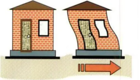
Inertia force in brief can be explained by Newton's Second Law of Motion, the inertia force F is mass M times acceleration A (F=M x A), and its direction is opposite to that of the acceleration. Clearly, more mass means higher inertia force. Therefore, lighter buildings sustain the earthquake shaking better. As the load transferred take place the inertia force experienced by the roof is transferred to the ground via the columns, causing forces in columns. The forces are also generated due to earthquake shaking, the columns undergo relative movement between their ends. As columns try to come back to the straight vertical position, i.e., columns resist deformations. In the straight vertical position, the columns carry no horizontal earthquake force through them. But, when forced to bend, they develop internal forces. The larger is the relative horizontal displacement u between the top and bottom of the column, the larger this internal force in columns.
Fig 3. - Inertia force in columns
IMPORTANCE OF SIZE AND SHAPE OF BUILDING DURING EARTHQUAKE
The behaviour of a building during earthquakes depends critically on its overall shape, size and geometry, in addition to how the earthquake forces are carried to the ground. A desire to create an aesthetic and functionally efficient structure drives architects to conceive wonderful and imaginative structures. Sometimes the shape of the building catches the eye of the visitor, sometimes the structural system appeals, and in other occasions both shape and structural system work together to make the structure a marvel.
Fig 4. -Shapes of building
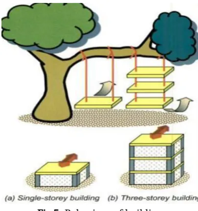
Twisting or torsional movement in a building is created due to irregularity in structure. As earthquake force act on the center of mass of building and its resultant acts at the center of stiffness of building. Due to difference in center of mass and center of stiffness of building torsional movement is generated. The twisting can be easily understood by the classic swing example.
Swing - a wooden cradle tied with coir ropes to the sturdy branch of an old tree.
that they are inverted swings. The vertical walls and columns are like the ropes, and the floor is like the cradle. Buildings vibrate back and forth during earthquakes. Buildings with more than one storey are like rope swings with more than one cradle.
Fig 5. Behaviour of building
IV. DESIGN LOADS FOR RESIDENTIAL BUILDINGS
Loads are a primary consideration in any building design because they define the nature and magnitude of hazards are external forces that a building must resist to provide a reasonable performance(i.e., safety and serviceability) throughout the structure’s useful life. The anticipated loads are influenced by a building’s intended use (occupancy and function); configuration (size and shape) and location (climate and site conditions).Ultimately, the type and magnitude of design loads affect critical decisions such as material collection, construction details and architectural configuration. Since building codes tend to vary in their treatment of design loads the designer should, as a matter of due diligence, identify variances from both local accepted practice and the applicable code relative to design loads as presented in this guide, even though the variances may be considered technically sound.
4.1 DEAD LOADS
Dead loads consist of the permanent construction material loads compressing the roof, floor, wall, and foundation systems, including claddings, finishes and fixed equipment. Dead load is the total load of all of the components of the components of the building that generally do not change over time, such as the steel columns, concrete floors, bricks, roofing material etc. In Etabs assignment of dead load is automatically done by giving the property of the member. In load case we have option called self-weight which automatically calculates self-weights using the properties of material.
4.2 IMPOSED LOADS
Live loads are produced by the use and occupancy of a building. Loads include those from human occupants, furnishings, no fixed equipment, storage, and construction and maintenance activities. As required to adequately define the loading condition, loads are presented in terms of uniform area loads, concentrated loads, and uniform line loads. The uniform and concentrated live loads should not be applied simultaneously a structural evaluation. Concentrated loads should be applied to a small area or surface consistent with the application and should be located or directed to give the maximum load effect possible in endues conditions. For example, the stair load should be applied to the centre of the stair tread between supports.
4.3 WIND LOADS:
locations on a building is complex to the point that pressures may become too analytically intensive for precise consideration in design. Therefore, wind load specifications attempt to amplify the design problem by considering basic static pressure zones on a building representative of peak loads that are likely to be experienced. The peak pressures in one zone for a given wind direction may not, However, occur simultaneously in other zones. For some pressure zones, the peak pressure depends on an arrow range of wind direction. Therefore, the wind directionality effect must also be factored into determining risk consistent wind loads on buildings. Assignment of wind speed is quite different compared to remaining loads. We have to define a load case prior to assignment.
4.4 EARTHQUAKE LOADS:
Earthquake or seismic load on a building depends upon its geographical location, lateral stiffness and mass, and is reversible. Its effect should be considered along both axes of a building taken one at a time. A force is defined as the product of mass and acceleration. During an earthquake, the mass is imparted by the building whereas the acceleration is imparted by ground disturbances. In order to have a minimum force, the mass of the building should be as low as possible. There can be no control on the ground acceleration as it is an act of God! The point of application of this internal force is the center of gravity of the mass on each floor of the building. Once there is a force, there has to be an equal and opposite reaction to balance the force. The inertial force is resisted by the building and the resisting force acts at the center of rigidity at each floor of the building or shear center of the building at each storey.
V. MODEL OUTPUT
a) output: 3d-model of a rc frame
c) diaphragm
e) bending moment diagram from analysis
f) shear force from analysis
VI. CONCLUSION
The Commercial building (g+9) was designed with the earthquake resistant design consideration. Seismic analysis and design were done and the structure was analyzed by seismic coefficient method with the help of ETABS software as per IS 1893-2002. The detailing of the structural elements were done as per IS 13920-1993 (Ductile detailing for Earthquake resistant
structures). To conclude a complete design involving several parameters so as to result the earthquake has been done.
VII.REFERENCES
[1].INDIAN STANDARD CODE BOOKS REFERRED:
a. IS: 875 (part I)-1987 – Code for practice for Design loads for Buildings and Structures [Dead load calculation] b. IS: 875 (part 2)-1987 – Code for
practice for Design loads for Buildings and Structures [Live load calculation] c. IS: 875 (part 3)-1987 – Code for
practice for Design loads for buildings and Structures [Wind load calculation] d. IS: 456-2000 for Plain and Reinforced Concrete code for practice (IV th Revision)
e. IS: 1893-2002 – Criteria for Earthquake Resistant Design of structures [Seismic load calculation] f. IS: 13920-1993 –Ductile Detailing of
Reinforced Concrete Structures subjected to seismic forces.
[2].ETABS – Integrated Building Design software manual by Computers and Structures Inc. [3].Earthquake Resistant Design of Structures
by Mr.Pankaj Aggarwal and Mr. Manish Shirkhande.