An FPGA Implementation Of Hearing Aids based
on Wavelet-Packets
Nivin Ghamry
Faculty of Computer and Information/Department of Information Technology, Cairo, Egypt Email: [email protected]
Abstract— Advances in digital signal processing and microelectronics have led to the development of superior digital hearing aids for ameliorating severe defects of hearing. The progress in field programmable gate arrays (FPGA) technology, especially for miniaturized system applications, allowed increasing sophisticated features to be built for better sound reproduction, keeping small size and low power consumption of the devices. In this paper the recent trend of combining interconnects of FPGAs with embedded microprocessors and related peripherals to form a complete system on a programmable chip is employed for the design of digital hearing aids. Wavelet packet transform is applied for speech compensation of the hearing loss. The wavelet packet module is described in VHDL, implemented on FPGA and then added as a peripheral to the processor system. The embedded software processor used is the MicroBlaze soft core processor. The chip used is Digilent XUP II Virtex-II Pro system FPGA containing audio codec LM4550. The features of the design are small area and fast processing and low cost.
Index Terms— hearing aids, FPGA; MicroBlaze, LM4550, wavelet packet transform
I. INTRODUCTION
Hearing aids are divided on the basis of functionality into three categories: analog, programmable analog- and digital hearing aids. Analog hearing aids are the least expensive type. Their drawback is that sound is amplified without discriminating of the different sounds in noisy environment. In programmable-analog hearing aids a programmable control circuitry is added to the analog audio circuitry to program the gain and adjust frequency settings. Digital hearing aids are capturing most of the market today. They score over their analog counterparts because of using advanced digital signal processing (DSP) algorithms to compensate speech signal and improve intelligibility in noisy environment, as well as echo or feedback cancellation[1]. Researchers have investigated several techniques suitable for hearing aid applications. These techniques include uniform filter banks [2] and [3], non uniform filter banks[4] and fast Fourier transform[5]. In these techniques the frequencies of the audio signal are split into different bands and then amplification is performed according to the different levels of hearing loss. Discrete Wavelet transform (DWT)and Wavelet packet transform (WPT) offer a
richer frequency analysis compared with the previous techniques and are therefore applied for speech compensation for sensory neural impairments, which require more sophisticated spectrum analysis as demonstrated in [6-8]. The toughest challenge for hearing aid designers is the implementation of the devices. The improvement of FPGA manufacturing technology facilitated the design of devices of low cost and power consumption [9]. In recent years using embedded soft-processor cores and implementing DSP modules in FPGA chips (System on Programmable Chip (SOPC)) are employed. In [10] a hearing aid design is implemented applying Nios II embedded processor and DSP module implemented on FPGA.
In this paper a design of digital hearing aid based on WPT for speech compensation is implemented using Digile XUP II Virtex-II Pro system. The FPGA on board is Xilinx XC2VP30. The system is implemented in software using the soft processor MicroBlaze from Xilinx, which facilitates cooperating with peripheral equipments. The WPT algorithm is described in VHDL and implemented on the FPGA and then integrated into the processor system as a peripheral. This makes the system run faster than DSP chip does, because of the strong ability of FPGA of parallel processing.
This paper is organized as follows, in Section 2 wavelet packet transform is reviewed and its application for speech compensation of the hearing impairment called recruitment of loudness is discussed, in section 3 the hardware architecture of the wavelet packet filter is described, in section 4 the software and hardware implementation flow of the proposed architecture on FPGA is explained and finally conclusions are given in section 5.
II. WAVELET PACKET TRANSFORM FOR LOUDNESS RECRUITMENT
transform. In this section the wavelet packets transform is reviewed and then its application for the compensation of hearing loss of a hearing impairment called recruitment of loudness is presented.
A. Wavelet Packet Transform Structure
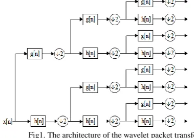
Wavelet packet transform was first introduced by Coifman et al [13] for dealing with the nonstationarities of the data. It has been applied as an efficient signal processing methods for multi-resolution analysis and local feature extraction of non-stationary signals. Fig 1 shows the basic structure of WPT, where h(n) and g(n) are the low- and high pass filters, respectively. In difference to the DWT, the filterbank is iterated over all frequency bands at each level, which leads to a full tree decomposition. The best-tree searching algorithm is then applied to decide a subset of the full tree as the final decomposition structure by measuring a data dependent cost function.
Fig1. The architecture of the wavelet packet transform
B. Loudness Recruitment
Loudness recruitment [14] is an abnormally rapid growth in loudness with increases in supra-threshold stimulus intensity. Recruitment is a common characteristic of hearing losses that result from damage to the sensory cells of the cochlea as a result of exposure, treatment with certain drugs, and advancing age in most cases. In these cases, patients experience a high-frequency loss, resulting in a reduced dynamic range of hearing and perceived loudness grows more rapidly with an increase in sound intensity than it does in the normal ear. Fig 2 is a plot of normal hearing curve versus a recruiting hearing loss for different sound pressure levels (SPL). The recruiting hearing loss which emerges above 0 dB on the y-axis and at 50 dB on the x-axis, means that the patient has low hearing sensitivity for signals at levels below 50 dB. As the figure shows the recruiting curve increases rapidly for signal levels above threshold and continues until about 20 dB above threshold. This is the point where recruitment is complete and above which loudness increases at the normal rate. A variety of techniques have been used to compensate for recruitment, for example amplitude compression with equalization and parametric compression [15]. Wavelet-based algorithm belongs to the parametric compression technique, where the parameters are the wavelet coefficients, each of them corresponding to a band of frequencies. The speech signal
Fig.2. Normal hearing versus hearing loss.
is reconstructed from the modified coefficients after applying an amplification gain. Fig3 shows the audiogram of a hearing loss example of a patient who suffers from mild hearing loss at low frequencies and severe hearing loss starting at the frequency of 1000 Hz associated with recruitment of loudness. The amplification process is as follows: For sounds of small SPL the gain is adjusted for overcoming the loss of sensitivity along the whole frequency range according to the different levels. The value of the gain is raised at 1000 Hz to smooth the transition from mild to severe loss. For sounds of larger SPL, the gain is adjusted at high-frequencies according to the loudness growth functionavoid discomfort caused by the reduced dynamic range of the listener.
Fig. 3 Precipitous high-frequency hearing loss.
**
(1)
Where
δ is the distance between the unamplified wavelet coefficient and the normal hearing threshold.
Δ is the dynamic range of a normal-hearing person (in dB).
Δ* is the dynamic range of a hearing- impaired person (in dB).
From the above relationship, compression gain for a coefficient can be derived as follows using logarithmic representations:
**
)
(
norimp
C
T
T
C
. (2)Where
Timp is the threshold of hearing of a hearing-impaired
person (in dB).
Tnor is the threshold of hearing of a normal person (in dB).
C* and C are the compensated and non-compensated wavelet coefficients, respectively.
III. THE BIORTHOGONAL WPT FILTER ARCHITECTURE
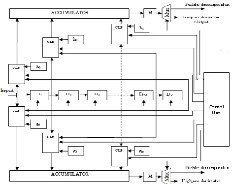
In this section the hardware architecture of the biorthogonal WPT is described. The biorthogonal 9, 7 tap wavelet filters are employed[17]. The architecture for the proposed biorthogonal wavelet filter is demonstrated in Fig 4. It consists of an N-tap delay line, processing elements and accumulators. The required area for hardware implementation is reduced by making use of the symmetry of the biorthogonal filters and employing multi clocks. Two input samples are added before multiplication with the corresponding filter coefficient. Each processing element comprises a multiplier and an adder. To obtain decimated outputs of the filters, the clock scheme generates two clocks such that the clock controlling the processing block is of twice the period of the clock for delay line as employed by the author in [18]. Three-level wavelet packet transform were necessary for obtaining good results as mentioned before. As the number of samples to be computed during one computing period in each level is the same, the computation of the coefficients at the different levels is overlapped. Memory blocks are used to store the intermediate coefficients required to obtain the samples of the following level of the WP tree. Each memory supports simultaneous read accesses for the computation of new coefficients, and write accesses after the computation. This is controlled by address generation circuits included in the control unit. Selection of a subtree according to the best tree algorithm is carried out by multiplexers. If a certain node is not to be decomposed then the processed coefficient is bypassed as a decimated output, else it is delivered to further decomposition in the following stage. The architecture of
Fig 4 Architecture of biorthogonal wavelet packet filters
processing elements, structure and memory requirements for the inverse WPT are analogous to those proposed for DWPT with little modifications according to the number of taps and different coefficients of the reconstruction filters.
IV. FPGA IMPLEMENTATION
Fig 5 shows the construction blocks of digital hearing aids which are: microphone, preamplifiers, anti-aliasing filters, analog to digital converter (ADC), a signal processing technique core, digital to analog converter (DAC), post amplifier and a speaker.
Fig. 5 Block diagram for a programmable digital hearing aid
The proposed hearing aid device is implemented on the Digilent XUP II Virtex-II Pro system. The FPGA on the board is a Xilinx XC2VP30 with 30,816 logic cells, 136 18-bit multipliers and 2448 kb BRAM The board contains the audio codec LM4550 chip which was specially designed to serves as an interface between the analog traditional audio components (e.g., headphones and microphones) and the FPGA and provide a high quality audio pass. The LM4550 uses 18-bit Sigma-Delta ADCs and DACs and provides 90 dB of dynamic range and a conversion rate of at least 16KHz. More about LM4550 can be found in [19]. In the following the software and hardware implementation are described.
A. Software Implementation
Fig..6 The block diagram of the software implementation
FPGA. Xilinx Platform Studio (XPS) is used to configure and build the specification of the embedded system. The aim here is to create DSP module (WPT core) and then integrate it into that processor system by adding it as a peripheral module. Fig6 shows the block diagram of the software implementation of the proposed design. The proposed system consists of the following items:
(1) MicroBlaze Processor,
(2) Local Memory Bus (LMB), BRAM (On-chip memory), LMB BRAM Controllers,
(3) On-chip Peripheral Bus (OPB),
(4) UART and Memory Debug Module
(OPB_MDM),
(5) General Purpose Input/Output peripheral (OPIO) On-chip Peripheral Bus (OPB) is the system backbone to connect the MicroBlaze to the memory and other peripherals. Digital Clock Manager (DCM) Module is used to generate the OPB system clock. OPB is clocked with OPB system clock 100 MHz and the AC’97 controller is clocked with the AC bit clock 12.228MHz.The OPB_MDM enables JTAC-based debugging for the Microblaze processor. The UART module connects the OPB to the serial port of the board. The Software controlling the MicroBlaze processor is written in C++ language. MicroBlaze is used to configure the LM4450 using GPIO as shown in Figure. The WPT signal processing module is described in VHDL. After testing and debugging, it is connected to the Microblaze processor as a peripheral. To connect the WPT to OPB an interface with Master slave signals is provided.
B. Hardware Implementation Flow
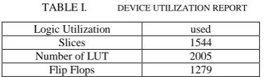
The building blocks for hardware implementation on FPGA are mainly the WPT and IWPT blocks and the Xilinx Dual port BRAM for storing intermediate results
(wavelet coefficients), filter coefficients and values for gain adjustment. The data and coefficient values comprise 16 bits. The device utilization report for the WPT core is given in Table 1.
TABLE I. DEVICE UTILIZATION REPORT
Logic Utilization used
Slices 1544
Number of LUT 2005
Flip Flops 1279
DAC of the AC97 chip via the SDATA-OUT pin which converts them to an analog waveform. This waveform is amplified by the amplifier contained at the output of the board and driven to the speaker. Latency of the system is 1 ms. Debugging was carried out using Modelsim. The proposed design is comparable with the design presented in[9] as well as with conventional digital hearing aids. The advantage of the design here over the previous one is using the Xilinx XC2VP30 board with the audio codec LM4550 chip, which is used for ADC and DAC conversion instead of building these blocks as separate modules as in the previous design which affects area and connection complexity and processing time. Furthermore it outperforms the conventional hearing aids in portability, nursing and small price, because of the low cost of FPGA exploitation. One of the features which can be added to improve the performance of the device in future work is denoising as denoising is one of the successful applications of WPT and on the other hand the latency of the device is small compared to the of listening which allows aiding more features.
V. CONCLUSIONS
In this paper a wavelet packet –based architecture for hearing aid device is implemented on FPGA. The FPGA used is a Xilinx XC2VP30, which contains an audio codec the LM4550 chip on board. The hearing aid device is a designed as a System on a Programmable Chip by combining the soft processor core Microblaze with WPT hardware module as a peripheral... The WPT module is described in VHDL and implemented on FPGA. The software controlling Microblaze is written in C++ and compiled using Xilinx's Embedded Development Kit for Xilinx MicroBlaze).
Software and hardware implementation as well as hardware resource utilization are given. The implementation fulfills the requirements of hearing aids like portability, easy usage, low price and good performance.
REFERENCES
[1] H. Levitt, ―A historical perspective on digital hearing aids:
how digital technology has changed modern hearing aids‖,
Trends in Amplification, vol.11, pp. 7-24, 2007.
[2] D. Alfsmann, H. G. Göckler, and T. Kurbiel, ―Filter Banks
for Hearing Aids Applying Subband Amplification: A Comparison of Different Specification and Design Approaches‖, In Europ.Sign. Process. Conf., Glasgow, Scotland, 2009..
[3] T.-B Deng, ―Three-channel variable filter-bank for digital
hearing aids‖, IET Transactions on Signal Processing,
vol. 4 , issue 2, pp. 181 – 196, April 2010.
[4] Y. L. Ying , ―Computationally efficient non uniform FIR
digital filter bank for hearing aids‖ , IEEE Trans. on
Circuits and Systems I: Regular Papers, vol. 52 (12), 2754 - 2762. Dec, 2005
[5] K.-s., Chong, B.-h., Gwee, J.S. Chang, ―Low energy
FFT/IFFT processor for hearing aids‖, Proceedings of the
IEEE International Symposium on Circuits and Systems ISCAS 2007, pp. 1169 - 1172 , New Orleans, May 2007.
[6] K.R., Borisagar, ―Speech processing using wavelet
transform and implementation for digital hearing aids‖,
International Conference on Emerging trend in Engineering, Pune, Dec. 2008
[7] R., Liang, Z. Cairong , Q. Wang, , Xi, J.,. ―Sound source
localization of digital hearing aids using wavelet based
multivariate statistical method‖, Journal of Electronics,vol.
27( 4), pp. 571-576, July 2010.
[8] N.Whitmal, , J. Rutledge, and J., Cohen, Denoising
speech signals for digital hearing aids: A wavelet based approach. In B.R J.Cohen, , and A. I., Zayed, Wavelets and multiscale analysis: Theory and Applications, Part 3, 299-331, Springer, 2011
[9] M. A. Trenas, , J.Ldpez and E. L Zapata, ―An architecture
for wavelet-packet based speech enhancement for hearing
aids‖, Proceedings of the IEEE International Conference
on Acoustics, Speech, and Signal Processing, vol. 2, pp.II849 - II852, June, 2000, Istanbul.
[10]Y., Min, ―Design of portable hearing aid based on FPGA‖,
Proceedings of the 4th IEEE International Conference of Industrial, Electronics and applications, ICIEA, pp.1895-1899, May 2009,
[11] S.G. Mallat, and S. Zhong, ―A theory for multiresolution
signal decomposition: the wavelet representation‖, IEEE
Trans on Pattern Analysis and Machine, vol. 11(7), pp.674-693, 1989.
[12]M. Smith, T.Barnwell,, ―Exact reconstruction techniques
for tree-structured subband coders‖, IEEE Trans on
Acoustics, Speech, and Signal Processing, vol. 34( 3), pp.434-441, 1986.
[13]R. Coifman., Y. Meyer, S.Quake and V. Wickerhauser,
―Signal processing and compression with wavelet
packets‖, Progress in wavelet analysis and applications,
pp. 77-93, 1993
[14]B. C. J. Moore, An introduction to the psychology of
hearing , Elsevier Academic Press, UK. 2004
[15]A.Ramasubramanian,; K.L Payton,.; A.H. Costa, ― A
comparison between conventional and wavelet based
amplitude compression schemes‖, Proceedings of the
IEEE-SP International Symposium on Time-Frequency and Time-Scale Analysis, pp. 161 – 164, Oct 1998, ,Pittsburgh, PA , USA.
[16] L. A., Drake, J. C. Rutledge, and J.Cohen, ―Wavelet
analysis in recruitment of loudness compensation‖, IEEE
Trans on Signal Processing, vol. 41(12), pp.3306 – 3312, 1993.
[17]M. Vetterli, ―Wavelet and filter banks:Theory and design‖,
IEEE Trans on and Signal Processing, vol. 40, pp.2207-2232, 1992
[18]N.A., Ghamry, S.E.-D. Habib; ―An Efficient FPGA
Implementation of a Wavelet Coder/Decoder‖, The twelfth International Conference on Microelectronics, ICM 2000, October, Tahran.
[19]http://www.xilinx.com