International Journal of Emerging Technology and Advanced Engineering
Website: www.ijetae.com (ISSN 2250-2459,ISO 9001:2008 Certified Journal, Volume 4, Issue 7, July 2014)
Spatial Modulation Based MIMO-OSDM for 4G Wireless
Systems under Rayleigh Fading Channel
Ritu Gupta
1, Megha Kataria
21Student, DCTM, Palwal, INDIA
2Assistant Professor (ECE) DCTM, Palwal, INDIA
Abstract—Because of the enormous capacity upsurge a
MIMO systems offer, such systems gained a lot of interest in mobile communication research. One indispensable problem of the wireless channel is fading, which occurs as the signal follows multiple paths between transmitter and receiver antennas. Fading can be mitigated by diversity, which means that the information is transmitted not only once but several times, hoping that at least one of the replicas will not undergo severe fading. There are various coding methods, a main issue in all these schemes is the exploitation of redundancy to achieve high reliability, high spectral efficiency and high performance gain for MIMO-OFDM systems earlier. In this paper, we are going to introduce an orthogonal spatial division multiplexing in which divide the central signal streams into both time and frequency. Also to increase the spatial diversity we are going to introduce spatial modulation along with STBC for our new MIMO-OSDM. Experimental results show that, proposed system outperform the existing MIMO-OFDM system in terms of performance measure for various modulation schemes.
Keywords— Multiple Input Multiple output (MIMO)
system, orthogonal spatial division multiplexing, space time block coding, spatial modulation, 4G wireless communication.
I. INTRODUCTION
High spectral efficiency and high transmission rate are
the challenging requirements of future
wireless broadband communications. In a multipath wireless channel environment, the deployment of Multiple Input Multiple Output (MIMO) systems leads to the achievement of high data rate transmission without increasing the total transmission power or bandwidth [1]. Multiple-Input Multiple-Output antenna systems are a form of spatial diversity. An effective and practical way to approaching the capacity of MIMO wireless channels is to employ space-time block coding in which data is coded through space and time to improve the reliability of the transmission, as redundant copies of the original data are sent over independent fading channels [2, 3]. Then all the signal copies are combined at the receiver in an optimal way to extract as much information from each of them as possible. OFDM can reduce the effect of frequency selective channel.
This is because OFDM is a multi-carrier transmission technique, which divides the available spectrum into many carriers, each one being modulated by a low-rate data stream. One popular combination of MIMO and OFDM is the STBC-OFDM. Furthermore, this work is motivated from such STBC-OFDM system to develop an orthogonal spatial division multiplexing system. In STBC coding is applied across multiple OSDM blocks to enhance the system Performance inherent in MIMO-OFDM system. The coding distributes symbols along different transmit antennas and time slots. In this context, the STBC-OSDM system is one of most promising system configurations that is adopted for 4th generation mobile systems [10].
The propagation of radio waves through the atmosphere including the ionosphere is not a simple phenomenon to model. Atmospheric propagation can show a wide range of behaviours based on factors like frequency, bandwidth of the signal, types of antennas used, terrain and weather conditions.The presence of these paths is due to atmospheric reflections, refractions and scattering. In a multipath fading environment if a line of sight (LOS) component is available then the channel is referred to as a Rician channel. On the other hand if there is no LOS component then the channel will be referred to as a Rayleigh fading channel.
A.Introduction to fourth generation of communication system
International Journal of Emerging Technology and Advanced Engineering
Website: www.ijetae.com (ISSN 2250-2459,ISO 9001:2008 Certified Journal, Volume 4, Issue 7, July 2014)
The three major radio air limit standards for 3G are wideband CDMA (WCDMA), time-division synchronous CDMA (TD-SCDMA), & CDMA 2000. The broadcasted data rate of 3G is up to 144 kb/s for high-mobility traffic, 384 kb/s for low-mobility traffic, & 2 Mb/s in good situation. However, there are two limitations with 3G. One is the difficult expansion to very high data rates such as 100 Mb/s with CDMA due to extreme interference between services. The other is the difficulty of providing a period of multirate services, all with different quality of service (QoS) & performance necessities, due to the limitations required on the core network by the air interference standard.
B.Principles of space-time (MIMO) systems
Consider the multi-antenna system. A compressed digital source in the form of a binary data stream is fed to a simplified transmitting block encompassing the functions of error control coding and (possibly joined with) mapping to complex modulation symbols (quaternary phase-shift keying (QPSK), M-QAM, etc.). The latter produces several separate symbol streams which range from independent to partially redundant to fully redundant. Each is then mapped onto one of the multiple TX antennas. Mapping may include linear spatial weighting of the antenna elements or linear
antenna space–time precoding. After upward frequency
conversion, filtering and amplification, the signals are launched into the wireless channel. At the receiver, the signals are captured by possibly multiple antennas and demodulation and demapping operations are performed to recover the message. The level of intelligence,
complexity, and a priori channel knowledge used in
selecting the coding and antenna mapping algorithms can vary a great deal depending on the application. This determines the class and performance of the multi-antenna solution that is implemented.
Simple linear antenna array combining can offer a more reliable communications link in the presence of adverse propagation conditions such as multipath fading and interference. A key concept in smart antennas is that of beam forming by which one increases the average signal-to-noise ratio (SNR) through focusing energy into desired directions, in either transmit or receiver. Indeed, if one estimates the response of each antenna element to a given desired signal, and possibly to interference signal(s), one can optimally combine the elements with weights selected as a function of each element response. One can then maximize the average desired signal level or minimize the level of other components whether noise or co-channel interference.
As subscriber units (SU) are gradually evolving to become sophisticated wireless Internet access devices rather than just pocket telephones, the stringent size and complexity constraints are becoming somewhat more
This makes multiple antenna elements transceivers a possibility at both sides of the link, even though pushing much of the processing and cost to the network’s side (i.e., BTS) still makes engineering sense. Clearly, in a MIMO link, the benefits of conventional smart antennas are retained since the optimization of the multi-antenna signals is carried out in a larger space, thus providing additional degrees of freedom. In particular, MIMO systems can provide a joint transmit-receive diversity gain, as well as an array gain upon coherent combining of the antenna elements.
C.Transmission over MIMO systems
Here, we summarize different MIMO transmission schemes, give the intuition behind them, and compare their performance.
General Principles
Current transmission schemes over MIMO channels typically fall into two categories: data rate maximization or diversity maximization schemes, although there has been some effort toward unification recently. The first kind focuses on improving the average capacity behaviour. For example, in the example shown in Fig, the objective is just to perform spatial multiplexing as we send as many independent signals as we have antennas for a specific error rate (or a specific outage capacity [2]). More generally, however, the individual streams should be encoded jointly in order to protect transmission against errors caused by channel fading and noise plus interference. This leads to a second kind of approach in which one tries also to minimize the outage probability, or equivalently maximize the outage capacity.
D.Structure of Assessment
The association steps of this paper is as follows. The Introductory Section ends with a brief introduction of MIMO systems and its necessity in today’s
communication. The part in introduction
shows a brief explanation about fourth generation of communication, principles of MIMO system and transmission over multiple input multiple output system.
In Section II, explains a General review and related work of different coding & multiplexing schemes in multiple antenna system, many techniques have been proposed for the MIMO systems which are categorized in this section.
International Journal of Emerging Technology and Advanced Engineering
Website: www.ijetae.com (ISSN 2250-2459,ISO 9001:2008 Certified Journal, Volume 4, Issue 7, July 2014)
Section IV gives details about the simulation results, it also shows some comparative graphs which prove that the proposed approach overcome the traditional approach.
Section V shows the observations, discussion and tabular comparison of different researches reviewed in previous sections and a general conclusion of the paper, regarding review is presented.
II. RELATED WORK
With the rapid improvement in wireless
communications & the reduced cost of communication devices, wireless networks have become denser & denser while bandwidth efficiency becomes more and more significant. It is usual to consider that multiple communication devices conduct transmission & reception cooperatively in a distributed method.
Utilizing multiple-input multiple-output (MIMO) in wireless communication systems has been proven to offer plenty of benefits in both increasing the system capacity and consistency of reception in rich scattering atmosphere [11, 12]. To take advantage of these a space-time block coding (STBC)-oriented diversity scheme has been generally adopted in future wireless communication standards [13], for instance 3GPP LTE, WiMax, etc. The STBC technique was initially proposed by Alamouti in [14], achieves transmit diversity exclusive of channel knowledge. Although Alamouti’s STBC was originally designed for two transmit antennas & one receive antenna, this method has been generalized by Tarokh in [15] & extended to the system for four transmit antennas. Space time Block Coding is a set of realistic signal design techniques aimed at approaching the information theoretic capacity bounds of Input Multiple-Output (MIMO) channels. Since the initial work of Alamouti [21], space-time coding has been a rapid growing field of research. In the last decade, numerous coding techniques have been proposed. These includes orthogonal (OSTBCs) [21]–[23], quasiorthogonal (QOSTBCs) [24], [25] & non-orthogonal STBCs (NOSTBCs) [26]
The outage analysis in [20] relies on the random coding argument & demonstrates that full spatial diversity can be achieved employing such a rich set of codes. Laneman et al. [27] proposes the use of “conventional” orthogonal space-time block coding (STBC) in a “distributed” manner for realistic implementation of user cooperation.
Nabar et al. [28], [29] evaluates distributed STBC operating in an amplify-&-forward (AF) mode through the derivation of pairwise error probability (PEP) terms. They show that the original design criterion for conventional STBC (i.e., rank & determinant criteria) still apply for the design of distributed STBC schemes under the supposition that appropriate power control rules are used at relays. An overview & comparison of these schemes can be found in [34]–[36]. In this paper, authors extend the three abovementioned equalization schemes to a relay-assisted transmission scenario, carefully utilizing the fundamental orthogonality of distributed STBC. Most of the existing literature on cooperative diversity assumes frequency-flat fading channel. Together with the conference version of this paper [37], there have been only a few sporadic results accounts on the broadband cooperative transmission techniques for frequency-selective channels. Yatawatta et al. [38] proposes an OFDM cooperative diversity system assuming AF relaying & derive upper bounds on the channel capacity. Building upon their preceding work on distributed STBC [40], Anghel et al. [41] studied the performance of a relay-assisted uplink OFDM-STBC scheme & derive an expression for the symbol error probability assuming DF with no error propagation. To the best of our knowledge, the conference version of the current paper [37] is the first effort to investigate TR-STBC & SC-TR-STBC in a relay-assisted transmission scenario (and OFDM-STBC along with the above mentioned papers [38], [39], [41]).
Fu Hong-liang et al., has anticipated a novel cyclic space time block code (STBC) scheme in MIMO CDMA system. In modern wireless communications multiple input & multiple output (MIMO) is a very promising scheme. MIMO functions are mainly diversity, beam forming. And the diversity can be achieved by means of space-time coding (STC). STC has two ways one is time trellis codes (STTC) & the other one is space-time block codes (STBC). STBC provides diversity with less encoding & decoding difficulty.
III. PROPOSED MIMOSYSTEM
International Journal of Emerging Technology and Advanced Engineering
Website: www.ijetae.com (ISSN 2250-2459,ISO 9001:2008 Certified Journal, Volume 4, Issue 7, July 2014)
[image:4.595.51.219.397.533.2]
Figure 1. Shows the transmitter side model of proposed work, we have to send only constellation points with respect to antenna
[image:4.595.351.510.559.686.2]number.
Figure 2. Shows the receiver side model for the proposed work. Perfect channel estimation is done to find best suited channel. Also,
Channel consist with Rayleigh Fading Environment.
A.Spatial Modulation
Spatial modulation (SM) is a recently developed transmission technique that uses multiple antennas. The basic idea is to map a block of information bits to two information carrying units:
1. A symbol that was chosen from a constellation
diagram and
2. A unique transmit antenna number that was chosen
from a set of transmit antennas.
The use of the transmit antenna number as an information-bearing unit increases the overall spectral efficiency by the base-two logarithm of the number of transmit antennas.
At the receiver, a maximum receive ratio combining algorithm is used to retrieve the transmitted block of information bits. Here, we apply SM to orthogonal spatial division multiplexing (OSDM) transmission.
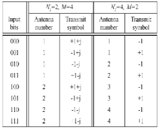
In general, any number of transmit antennas and any digital modulation scheme can be used. The constellation diagram and the number of transmit antennas determine the total number of bits to be transmitted on each sub-channel at each instant.
The combination of BPSK and four transmit antennas in this illustration in a total of three information bits to be transmitted on each sub-channel. Instead, four quadrature-amplitude modulation (QAM) and two transmit antennas can be used to transmit the same number of information bits, as shown in Table below. The number of bits that can be transmitted on each
OSDM sub-channel for a system that uses a QAM
constellation diagram of size M (m = log2(M)) and Nt
transmit antennas.
This shows that the constellation diagram and the number of transmit antennas can be traded off for any number of transmitted information bits.
In SM, a block of any number of information bits is mapped into a constellation point in the signal domain and a constellation point in the spatial domain. At each time instant, only one transmit antenna of the set will be active. The other antennas will transmit zero power. Therefore, ICI at the receiver and the need to synchronize the transmit antennas are completely avoided. At the receiver, maximum receive ratio combining (MRRC) is used to estimate the transmit antenna number, after which the transmitted symbol is estimated. These two estimates are used by the spatial demodulator to retrieve the block of information bits.
SM MAPPING TABLE: b/SYMBOL/SUBCHANNEL
Input Data
Spatial Modulation
Data encoding using Space time Block
codes Multiplexing using our
orthogonal spatial division multiplexing
Channel with Fading Environment This Spatial Division is done using Discrete
Wavelet transform
Output Data
Data decoding using Space time Block
codes
De-multiplexing using our orthogonal spatial division
multiplexing Perfect Channel
Estimation
International Journal of Emerging Technology and Advanced Engineering
Website: www.ijetae.com (ISSN 2250-2459,ISO 9001:2008 Certified Journal, Volume 4, Issue 7, July 2014)
B.Orthogonal Spatial Division Multiplexing
In our case the spatial division multiplexing is performed using discrete wavelet transform as fast Fourier transform used in orthogonal frequency division multiplexing can split the signal into frequency signal only. The transform of a signal is just another form of representing the signal. It does not change the information content present in the signal. The Wavelet Transform provides a time-frequency representation of the signal. It was developed to overcome the short coming of the Short Time Fourier Transform (STFT), which can also be used to analyze non-stationary signals. While STFT gives a constant resolution at all frequencies, the Wavelet Transform uses multi-resolution technique by which different frequencies are analyzed with different resolutions.
OSDM is a multi-carrier modulation (MCM) technique. It is a suitable modulation used for high data rate transmission and is able to mitigate the effects of inter symbol interference (ISI) and inter carrier interference (ICI). In an SFDM scheme, a huge number of orthogonal, overlapping, narrow band sub-channels, transmitted in parallel subdividing the existing transmission bandwidth. The overlapping of the sub-channels do not create any problems since the peak of one subcarrier occurs at zeroes of other subcarriers. Orthogonality between the different subcarriers is
achieved by using CWT. Figure 6 depicts the spectrum
for 5 different frequencies where, is the subcarrier
spacing. We clearly see that for the red and green peaks the dashed lines cross from the zero crossings of the other carriers [29].
C.Transceiver of proposed OSDM system
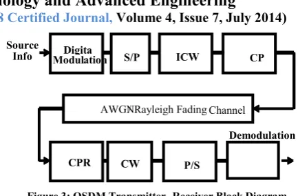
[image:5.595.317.534.112.254.2]The general block diagram of an OSDM transceiver has been shown in Figure 3. The digital data if first up-converted by a modulation scheme and then the symbols are put into parallel streams that the CWT block is going to work on. After ICWT is taken an appropriately sized cyclic prefix is appended at the end of the signal. Finally, the signal is sent into the channel. This channel is either the AWGN or the flat fading Rayleigh channel. At the receiver the first task is to remove the cyclic prefix and then apply CWT. Afterwards, the parallel streams are serialized and then the symbols put through the demodulator for obtaining the input source data.
Figure 3: OSDM Transmitter- Receiver Block Diagram
Once the cyclic prefix is removed taking IFFT of the signal is equivalent to multiplying the constellation points by sinusoids whose frequencies are equal to the frequency of a carrier signal and then summing these products.
The complex wavelet transform (CWT) is a complex-valued extension to the standard discrete
wavelet transform (DWT). It is a
two-dimensional wavelet transform which provides
multi-resolution, sparse representation, and useful
characterization of the structure of an image. Further, it purveys a high degree of shift-invariance in its magnitude. However, a drawback to this transform is that it is exhibits (where is the dimension of the signal being transformed) redundancy compared to a separable (DWT).
D.Space-time Coding
Space-Time Codes (STCs) have been implemented in cellular communications as well as in wireless local area networks. Space time coding is performed in both spatial and temporal domain introducing redundancy between signals transmitted from various antennas at various time periods. The research on STC focuses on improving the system performance by employing extra transmits antennas. Constructing STC, researcher have to trade-off between three goals: simple decoding, minimizing the error probability, and maximizing the information rate.
The essential question is: How can we maximize the
transmitted date rate using a simple coding and decoding algorithm at the same time as the bit error probability is minimized?
Space-Time Coded Systems
Let us consider a space-time coded communication
system with nt transmit antennas and nr receive antennas.
The transmitted data are encoded by a space-time
encoder. At each time slot, a block of m·nt binary
information symbols
Demodulation Digita
l
Modulation ICW T
AWGN / Rayleigh Fading Channel
CPR CW T
P/S
S/P CP
I Source
International Journal of Emerging Technology and Advanced Engineering
Website: www.ijetae.com (ISSN 2250-2459,ISO 9001:2008 Certified Journal, Volume 4, Issue 7, July 2014)
c
Is fed into the space-time encoder. The encoder maps
the block of m binary data into nt modulation symbols
from a signal set of constellation M = 2m points. After
serial-to-parallel (SP) conversion, the nt symbols
Are transmitted simultaneously during the slot t from
nt transmit antennas. Symbol , is
transmitted from antenna i and all transmitted symbols
have the same duration of T sec. The vector in equation
above is called a space-time symbol and by arranging the
transmitted sequence in an array a of nt × N space-time
code-word matrix.
Can be defined as The i-th row s
is the data sequence transmitted form the i-th transmit
antenna and the j-th column is
the space-time symbol transmitted at time j,1 to N.
As already explained, the received signal vector can be calculated as
Y = HS + N.
The MIMO channel matrix H corresponding to nt
transmit antennas and nr receive antennas can be
represented by an nr × nt matrix:
Where the ji-th element denoted by htj,i, is the fading
gain coefficient for the path from transmit antenna i to
receive antenna j. At the receiver, the decision metric is
computed based on the squared Euclidian distance between all hypothesized receive sequences and the actual received sequence:
Given the receive matrix YS with smallest Euclidian
distance d2H.The most commonly used distribution
functions for the fading envelopes are Rice, Rayleigh and Nakagami-m. Rayleigh is a special case of Nakagami-m, when m equals one. The fading models are related to some physical conditions that determine what distribution that best describe the channel.
The Rayleigh distribution assumes that there are a
sufficiently large number of equal power multipath components with different and independent phase.
The Nakagami one distribution equals the Rayleigh
distribution above. It is a general observation that an increased m value corresponds to a lesser amount of fading and a stronger direct path.
IV. RESULTS &DISCUSSION
In this section we will be presenting the link level performance of STBC and SM coded OSDM using either BPSK or QPSK modulation. All simulations have been carried out using the readily available MATLAB platform and writing dedicated functions for different parts. The simulation results obtained have been presented in four parts. The first part provides the bit error rate performance for BPSK modulated data transmitted over a Rayleigh fading channel. This is then followed by a performance analysis of OFDM over the AWGN channel using either BPSK or QPSK modulation. Third part demonstrates the BER vs. SNR for Alamouti STBC and Spatial modulation coded data transmitted over a Rayleigh fading channel without using OSDM. Finally, part four will provide STBC and SM coded OFDM performance when BPSK and QPSK are the preferred modulation and the channel is again the Rayleigh fading channel.
International Journal of Emerging Technology and Advanced Engineering
Website: www.ijetae.com (ISSN 2250-2459,ISO 9001:2008 Certified Journal, Volume 4, Issue 7, July 2014)
And for the AWGN channel Pb is defined as:
The advantage in multiple antenna schemes is that they use a new dimension called space in addition to time. Multiplexing gain, antenna gain and diversity gain are three main benefits of MISO and MIMO type systems. Alamouti scheme is known as the first STBC. It
uses two transmit antennas and Nr receive antennas.
Alamouti STBC has a unity rate and can attain a diversity
order of 2*Nr. Spatial modulation (SM) is a recently
developed transmission technique that uses multiple antennas. The basic idea is to map a block of information bits to two information carrying units: A symbol that was chosen from a constellation diagram and A unique transmit antenna number that was chosen from a set of transmit antennas.
This section will provide BER analysis for Alamouti STBC and SM over slow fading Rayleigh channels. For both schemes the simulations have been carried out using two transmit and one receive antenna.
2 4 6 8 10 12 14 16
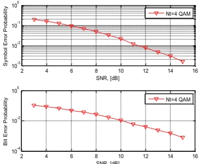
10-3 10-2 10-1 100 SNR, [dB] S y m b o l E rr o r P ro b a b ili ty Nt=4 QAM
2 4 6 8 10 12 14 16
10-4 10-2 100 SNR, [dB] B it E rr o r P ro b a b ili
[image:7.595.330.523.143.283.2]ty Nt=4 QAM
Figure 8. Comparison of Bit error probability and symbol error probability with respect to signal to noise ratio in case of 4 antenna
quadrature amplitude modulation.
2 4 6 8 10 12 14 16
10-3 10-2 10-1 100 SNR, [dB] S ym bo l E rr or P ro ba bi lit y Nt=2 QAM
2 4 6 8 10 12 14 16
10-3 10-2 10-1 SNR, [dB] B it E rr or P ro ba bi lit
y Nt=2 QAM
Figure 4. Comparison of Bit error probability and symbol error probability with respect to signal to noise ratio in case of 2 antenna
quadrature amplitude modulation.
2 4 6 8 10 12 14 16
10-3 10-2 10-1 100 SNR, [dB] S ym bo l E rr or P ro ba bi lit y Nt=4 BPSK
2 4 6 8 10 12 14 16
10-3 10-2 10-1 100 SNR, [dB] B it E rr or P ro ba bi lit
[image:7.595.323.530.332.482.2]y Nt=4 BPSK
Figure 5. Comparison of Bit error probability and symbol error probability with respect to signal to noise ratio in case of 4 antenna
binary phase shift keying modulation.
2 4 6 8 10 12 14 16
10-3 10-2 10-1 100 SNR, [dB] S ym bo l E rr or P ro ba bi lit y Nt=2 BPSK
2 4 6 8 10 12 14 16
10-3 10-2 10-1 100 SNR, [dB] B it E rr or P ro ba bi lit
y Nt=2 BPSK
Figure 6. Comparison of Bit error probability and symbol error probability with respect to signal to noise ratio in case of 2 antenna
[image:7.595.61.259.407.568.2]International Journal of Emerging Technology and Advanced Engineering
Website: www.ijetae.com (ISSN 2250-2459,ISO 9001:2008 Certified Journal, Volume 4, Issue 7, July 2014)
2 4 6 8 10 12 14 16
10-3 10-2 10-1 100
SNR, [dB]
S
ym
bo
l E
rr
or
P
ro
ba
bi
lit
y
Nt=4 QAM Nt=2 QAM Nt=4 BPSK Nt=2 BPSK
2 4 6 8 10 12 14 16
10-3 10-2 10-1 100
SNR, [dB]
B
it
E
rr
or
P
ro
ba
bi
lit
y
[image:8.595.63.288.137.302.2]Nt=4 QAM Nt=2 QAM Nt=4 BPSK Nt=2 BPSK
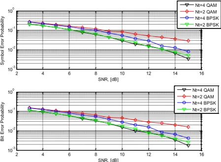
Figure 7. Overall Comparison of proposed SM-STBC-OSDM system for different modulation schemes and antenna numbers.
V. CONCLUSION &DISCUSSION
In this paper, we first compared the BER performance of 4×1 and 2×1 transmit diversity STBC data transmission over a Rayleigh fading channel using both BPSK and QPSK modulation. The communication system used spatial modulation to encode random data signal to achieve a higher transmit diversity. The proposed multiplexing system using complex wavelet transform we named it as orthogonal spatial division multiplexing which is motivated from orthogonal frequency division multiplexing performs better in multiple input multiple output system. Results with BPSK modulation indicate that using two antennas at the receiver instead of one will bring approximately an extra gain of 9dB at a BER value of 10-4.
Also comparison between 2×1 STBC using BPSK and 2×1 STBC using QPSK indicate that STBC with BPSK modulation would be ~4.2 dB better than the 2×1 STBC with QPSK for BER value of 10-3. These results indicate that to get a better performance over a Rayleigh fading channel MIMO approach would be better than MISO case and low level modulation should be preferred.
In the second phase of the simulations, transmission of data encoded using STBC and spatial modulation over a Rayleigh fading channel was compared. Since the STBC scheme makes use of a channel estimate and spatial modulation does not for both BPSK and QPSK modulations, the BER performance for STBC was better using spatial modulated encoded data. This however does not mean that spatial modulation should not be considered. In fact when there is high mobility and the channel conditions are fluctuating rapidly it may be difficult to obtain estimates for the channel and the detection of transmitted.
In the third phase of the simulations the transmit diversity schemes were combined with the proposed OSDM scheme and STBC-OSDM vs. SM-STBC-OSDM BER performance was obtained over a Rayleigh fading channel. The usage of a multi-carrier modulation technique was seen to further improve the BER results obtained when data was transmitted after encoding by STBC or SM. For both BPSK and QPSK modulations the boost introduced to the BER performance by combining OSDM with the chosen transmit-diversity technique would become more significant after 6dB. At a BER of 10-3 this difference in gain is around 4.5dB for STBC OSDM using BPSK and ~6dB for STBC OSDM using QPSK modulation. Then 2×1 DSTBC and OSDM is used back to back similar behavior is experienced however the BER performances are higher due to the fact that detection is done incoherently.
The improvement in BER performance when OSDM is used mainly comes due to the use of the guard interval. When the duration of the guard interval is selected larger than the maximum excess delay time of the radio channel this will help reduce the inter-symbol interference in a fading environment and help improve the BER results. Secondly since OSDM splits a broadband channel into multiple sub-channels this changes the behavior of each sub-channel to be flat fading and hence better performance can be observed.
VI. FUTURE WORK
The work described herein mainly concentrated on MIMO-OSDM based systems for 4G. However the higher Generation communication systems must adopt OSDMA, a multi user version of OSDM as the IMT-Advanced standard dictates. Therefore the future work will involve simulating OSDMA physical layer along with MIMO transmit and receive diversity techniques.
International Journal of Emerging Technology and Advanced Engineering
Website: www.ijetae.com (ISSN 2250-2459,ISO 9001:2008 Certified Journal, Volume 4, Issue 7, July 2014)
REFERENCES&ALLUSIONS
[1] G. J. Foschini, M. J. Gans, “On Limits of Wireless
Communications in Fading Environments when Using Multiple Antennas”, Wireless Personal Communications, vol. 6, pp. 311-335, March 1998.
[2] V. Tarokh, N. Seshadri, A. R. Calderbank, “Space-Time Codes
for High Data Rate Wireless Communication: Performance Criterion and Code Construction”, IEEE Trans. Inform. Theory, vol. 44, no. 2, pp. 744-765, March 1998.
[3] Z. Liu, G. B. Giannakis, S. Zhou, B. Muquet, ”Space-time coding
for boradband wireless communications”, Wireless
Communications and Moblie Computing, vol. 1, no. 1. pp. 35-53, Jan. 2001.
[4] J. H. Winters, ”On the capacity of radio communication systems
with diversity in a Rayleigh fading environment”, IEEE Journal on Selected Areas in Communications, pp. 871-878, June 1987.
[5] A. Wittneben, ”A new bandwidth efficient transmit antenna
modulation diversity scheme for linear digital modulation”, IEEE Int. Conference on Com., vol. 3, pp. 1630 - 1634, Geneva, May 1993.
[6] V. Tarokh, N. Seshadri, A. R. Calderbank, “Combined Array
Processing and Space-Time Coding”, IEEE Trans. Inform. Theory, vol. 45, no. 5, pp. 1121 - 1128, May 1999.
[7] A. Hottinen, O. Tirkkonen, R. Wichman, ”Multi-Antenna
Transceiver Techniques for 3G and Beyond”, John Wiley and Son Ltd. 2003.
[8] M. K. Simon, M.-S. Alouini, Digital Communication over Fading
Channel: A Unified Approach to Performance Analysis, John Wiley &Sohn, 2000.
[9] T. S. Rappapot, Wireless Communications: Principles and
Practice, Prentice Hall, 1996.
[10] IE Telatal, Capacity of multiple-antenna Gaussian channel.
European Trans Telecommunication .10.585595 (1999). doi:10.1002/ett.4460100604
[11] GJ Foschini, MJ Gans, on limits of wireless communications in a
fading environment when using multiple antennas. Wireless Personal Communication. 6(3), 311–335 (1998). Doi: 10.1023/a: 1008889222784
[12] 3rd Generation Partnership Project, TS36.211 Physical Channels
and Modulation. (2009)
[13] SM Alamouti, A simple transmit diversity technique for wireless
communications. IEEE J Sel Areas Communication. 16(8), 1451– 1458 (1998). doi:10.1109/49.730453
[14] V Tarokh, H Jafarkhani, AR Calderbank, Space-time block codes
from orthogonal designs.
[15] S. M. Alamouti, “A simple transmit diversity technique for
wireless communications,” IEEE Journal on Select Areas in Communications, vol. 16, no. 8, pp. 1451–1458, Oct. 1998.
[16] S. Mudulodu and A. Paulraj, “A transmit diversity scheme for
frequency selective fading channels,” in Proc. IEEE Global Telecommunications Conference 2000, GLOBECOM 2000, vol. 2. San Francisco, USA, Nov. 2000, pp. 1089–1093.
[17] A. Vielmon, Y. Li, and J. R. Barry, “Performance of Alamouti
transmit diversity over time–varying Rayleigh–fading channels,” IEEE Trans. On Wire. Communication. vol. 3, no. 5, pp. 1369– 1373, Sept. 2004.
[18] D. B. Lin, P. H. Chiang, and H. J. Li, “Performance analysis of
two– branch transmit diversity block–coded OFDM systems in time–varying multipath Rayleigh–fading channels,” IEEE Trans. on Veh. Technol., vol. 54, no. 1, pp. 136–148, Jan. 2005.
[19] Y. Ma and M. P¨atzold, “Performance comparison of space-time
coded MIMO-OFDM systems using different wideband MIMO channel models,” in Proc. 4th IEEE International Symposium on Wireless Communication Systems, ISWCS 2007. Trondheim, Norway, Dec. 2007, pp.762–766.
[20] S. Alamouti, “A simple transmit diversity technique for wireless
communication, "IEEE J. Sel. Areas Commun., vol. 16, no. 8, pp. 1451-1458, 1998.
[21] V. Tarokh, H. Jafarkhani, and A. Calderbank, “Space time block
codes from orthogonal designs," IEEE Trans. Inf. Theory, vol. 45, no. 5, pp. 744-765, 1999.
[22] G. Ganesan and P. Stoica, “Space-time block codes: a maximum
SNR approach," IEEE Trans. Inf. Theory, vol. 47, no. 4, pp. 1650-1656, 2001.
[23] H. Jafarkhani, “A quasi-orthogonal space-time block code," IEEE
Trans. Commun., vol. 49, no. 1, pp. 1-4, 2001.
[24] A. Boarui and D. Ionescu, “A class of nonorthogonal rate-one
spacetime block codes with controlled interference," IEEE Trans. Wireless Commun., vol. 2, no. 2, pp. 270-276, 2003.
[25] H. Jafarkhani, Space-Time Coding: Theory and Practice.
Cambridge University Press, 2005.
[26] J. N. Laneman and G. W.Wornell, “Distributed space-time-coded
protocols for exploiting cooperative diversity in wireless networks,” IEEE Trans. Inf. Theory, vol. 49, no. 10, pp. 2415– 2425, Oct. 2003.
[27] R. U. Nabar, H. Boelcskei, and F. W. Kneubhueler, “Fading relay
channels: performance limits and space-time signal design,” IEEE J. Sel. Areas Commun., vol. 22, pp. 1099–1109, Aug. 2004.
[28] R. U. Nabar and H. Boelcskei, “Space-time signal design for
fading relay channels,” in IEEE GLOBECOM, San Francisco, CA, Dec. 2003.
[29] A. F. Naguib and N. Seshadri, “MLSE and equalization of
space-time coded signals,” in IEEE Vehicular Technology Conf. (VTC’00)— Springer, May 2000.
[30] E. Lindskog and A. Paulraj, “A transmit diversity scheme for
channels with intersymbol interference,” in Proc. Int. Conf. Commun., New Orleans, LA, Jun. 2002.
[31] E. Lindskog and A. Paulraj, “A transmit diversity scheme for
channels with intersymbol interference,” in Proc. Int. Conf. Commun., New Orleans, LA, Jun. 2002.
[32] N. Al-Dhahir, “Single carrier frequency domain equalization for
space time block coded transmissions over frequency selective fading channels,” IEEE Commun. Lett., vol. 5, no. 7, pp. 304– 306, Jul. 2001.
[33] Z. Liu, G. B. Giannakis, A. Scaglione, and S. Barbarossa, “Block
precoding and transmit-antenna diversity for decoding and equalization of unknown multipath channels,” in Proc. 33rd Asilomar Conf. Signals, Syst., Comput., Pacific Grove, CA, Nov. 1999.
[34] N. Al-Dhahir, “Overview and comparison of equalization
schemes for space-time coded signals with application to EDGE,” IEEE Trans. Signal Process., vol. 50, no. 10, Oct. 2002.
[35] N. Al-Dhahir, M. Uysal, and C. N. Georghiades, “Three
space-time block coding schemes for frequency-selective fading channels with application to EDGE,” in Proc. IEEE Vehicular Technology Conf. (VTC’01)—Fall, Oct. 2001, pp. 1834–1838.
[36] H. Mheidat, M. Uysal, and N. Al-Dhahir, “Comparative analysis
of equalization techniques for STBC with application to EDGE,” in Proc. IEEE Vehicular Technology Conf. (VTC’04)—Spring, Milan, Italy, May 2004.
[37] H. Mheidat and M. Uysal, “Equalization techniques for
International Journal of Emerging Technology and Advanced Engineering
Website: www.ijetae.com (ISSN 2250-2459,ISO 9001:2008 Certified Journal, Volume 4, Issue 7, July 2014)
[38] S.Yatawatta and A. P. Petropulu, “AmultiuserOFDMsystem with
user cooperation,” in 38th Asilomar Conf. Signals, Syst., Comput,,
Pacific Grove, CA, Nov. 2004.
[39] S. Barbarossa and G. Scutari, “Distributed space-time coding for
multihop networks communications,” in IEEE Int. Conf. Communications (ICC), Paris, France, Jun. 2004.
[40] P. A. Anghel and M. Kaveh, “Exact symbol error probability of a
cooperative network in a Rayleigh-fading environment,” IEEE Trans. Wireless Commun., vol. 3, no. 5, pp. 1416–1421, Sep. 2004.
[41] ——, “Relay assisted uplink communication over
frequency-selective channels,” in IEEE Int. Workshop Signal Processing Advances for Wireless Communications (SPAWC) 2003, New York, Jun. 15–18, 2003.
[42] Volipour M., Shafiee H., “Performance of MC-CDMA Systems
with space-time block codes in frequency selective fading channels”, Int. Conf. on Communications Systems (ICCS 04), Sept 2004, pp. 645-649.
[43] Min Shi, Claude D. amours, “MIMO-CDMA Systems Using