© 2017, IRJET | Impact Factor value: 5.181 | ISO 9001:2008 Certified Journal | Page 1496
To Diminish the Voltage Sag Replaced DVR with Generalized
Modulation Strategy for Matrix Converter
Namrata Gupta
1, Manish Awasthi
21
M. Tech Student,
Dept. of ElectricalEngineering, JNCT
College, Rewa (MP), India2Assis
tant
Professor Dept. of ElectricalEngineering, JNCT
College, Rewa (MP), India---***---Abstract -
In the earlier period, the Power Quality (PQ) has developed into critical problem in mechanized industries and sensitive load centers. The voltage quality is most important part of the PQ. The voltage instability is generated in the form of voltage sag, swell and harmonics. In the past few years, the power electronic has been proposed the solutions to avoid these problems. The Dynamic Voltage Restorer (DVR) is the solutions to diminish the voltage sag. Dynamic Voltage Restorer (DVR) is used to protect sensitive loads against generated voltage disturbances. It is a solution for power system applications. The proposed model in this paper replaces the conventional AC-DC-AC converter by a Matrix Converter therefore avoiding bulky energy storage devices; though retain the knack to compensate for indistinct time withvery high power density.It protects sensitive loads from the
various types of disturbances of the power supply.
Key Words
:
Dynamic voltage restorer (DVR), Matrix converter, Matlab/Simulink, Voltage sags, Voltage swells.
1. INTRODUCTION
DVR is of great importance in present day’s power system. DVR is used to protect sensitive loads against voltage disturbance can occurs into two forms either voltage or voltage swell. it is a type of forceful or solution of power system application fault at either the transmission or distribution level may cause voltage sag and swell in the entire system or a large part of it. Voltage sag occurs at any time in the system. The ratio of the amplitude is 10-90% and the time duration can take a half cycle of one minute [1].
1.1 Voltage sag
[image:1.595.312.553.204.332.2]Voltage sag is defined as the drop of RMS voltage among 0.1 p.u. and 0.9 p.u. and durable between 0.5 cycles to 1 minute. Voltage sag are typically cause by the fault of the system. It is caused by asymmetrical line to line, single and double-line-to-ground and symmetrical three phase faults effects on sensitive loads, the DVR injects the voltages to restore and maintain the sensitive to its supposed value The insertion power of the DVR with minimum power for compensation purposes can be achieved by selecting an amplitude and phase angle.
Fig -1: Voltage sag
Voltage sag and swell can cause by the failing of the sensitive equipment like shutdown, large unbalance current, fuses or trip breakers. It may be very expensive for the customers. With the use of Dynamic Voltage restorer it Dynamic Voltage restorer can be eliminate this problem.
2. DYNAMIC VOLTAGE RESTORER (DVR)
A Dynamic Voltage Restorer (DVR) is series connected devices that inject supply voltage into the system; to control the load voltage. DVR was installed at the first time in 1996. Generally it is installed in a distribution system between the supply and load feeder. Its most important function is to quickly boost up the load voltage in form of disturbance in order to avoid any power disruption in load. There are varieties of circuit topology and control scheme that can be used to apply a DVR. In the addition of voltage sags and swells compensation, DVR has some other features such as: line voltage harmonics compensation, reduction of transients in voltage and fault current limitations.
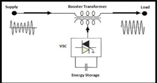
The basic configuration of DVR is consists of a Booster transformer, a Harmonic filter, a Voltage Source Converter (VSC) and a Control & Protection system as shown in Fig-2.
[image:1.595.309.565.617.752.2]© 2017, IRJET | Impact Factor value: 5.181 | ISO 9001:2008 Certified Journal | Page 1497 Dynamic Voltage Restorer (DVR) is used to protect the
sensitive loads against voltage instability. So the conservative DVR will be very huge, making its power density will be smaller, requiring continuous maintenance. As the compensation period increases the size the conventional DVR also increases. The proposed model in this paper replaces the conventional AC-DC-AC converter by a Matrix Converter due to avoiding bulky energy storage devices.
Dynamic Voltage Restorer (DVR) may be consisting with the combination of various parts, like;
1. Injection /Booster transformer
2. Harmonics Filter
3. Voltage Source Converter
4. Energy Storage Device/ Control System
5. By–pass Equipment
2.1 Injection
/
Booster transformer
The Injection / Booster transformer is a particularly designed transformer that limits the coupling of noise and transient energy from the source side to the load side. Its main tasks are:
1) It connects the DVR to the distribution network via the HV-windings and transforms and couples the injected compensating voltages generated by the voltage source converters to the incoming supply voltage.
2) In addition, the Injection / Booster transformer serves the purpose of isolating the Load from the system (VSC and control mechanism).
2.2 Harmonic filter
The main operation of harmonic filter is to maintain the harmonic voltage content generated by the voltage source converters (VSI) to the acceptable level (i.e., Eliminate the harmonics with high frequency switching).It has a small approximate rating 2% of the load MVA.
2.3 Voltage source converter
The converter is principally liable a Voltage Source Converter (VSC), which is Pulse width modulates (PWM) the DC from the DC-link/storage to AC-voltages injected into the system. A Voltage Source Converter (VSC) is a power electronic device which is consists by a storage device and switching device, which can be generated a sinusoidal voltage or sinusoidal waveform at any essential frequency, magnitude, and phase angle. In the application of DVR, the Voltage Source Converter (VSC) is used to momentarily change in the supply voltage or to generate a part of the supply voltage which is absent.
2.4 Energy storage device/ Control system
A DC-link voltage is used in the VSC to produce an
AC voltage into the network and during a majority of
voltage sag active power booster is necessary to
re-establish the supply voltages.
The main task of dc charging circuit is:
1.
The first task is to charge the energy source
after a sag compensation event.
2.
The second task is to maintain dc link voltage
at the nominal dc link voltage.
2.5 By-Pass Equipment
During faults, overload and service a bypass path for the load current has to be ensured.
[image:2.595.315.556.326.466.2]3. EQUIVALENT CIRCUIT OF DVR
Fig -3: Equivalent Circuit of DVR
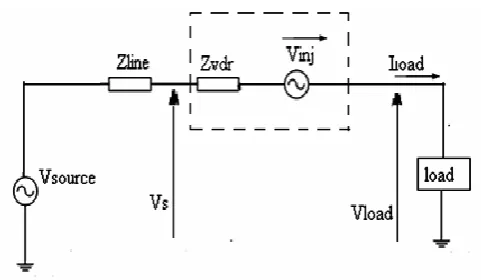
The equivalent circuit of the DVR is shows in Fig-3, when the source voltage is fall or raise, the Dynamic Voltage Restorer (DVR) inject a series voltage Vinj by injection transformer so that the desired magnitude of load voltage VL can be maintained. The series injected voltage of the DVR can be written as:
Vinj = VL + Vs (1)
Where,
VL = Desired Load Voltage Magnitude
Vs = Source Voltage During Sags/Swells Condition Il = Load Current
It is given by,
© 2017, IRJET | Impact Factor value: 5.181 | ISO 9001:2008 Certified Journal | Page 1498
[image:3.595.57.287.117.234.2]4. LOCATION OF DVR
Fig -4: Location of DVR
[image:3.595.313.556.264.412.2]The supplement of a DVR at the low voltage 4-wire 440 V level is shown in Fig-4. The increase in impedance by insertion of a small rated DVR can be significant for the load to be protected from voltage dips. Thereby, the per cent change in the impedance (Zincrease, %) in can be increased by several hundred per cent.
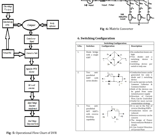
Fig -5: Operational Flow Chart of DVR
5. MATRIX CONVERTER
The matrix converter is consists by the combination of 9 Bi-directional (18 IGBT + 18 Diodes) switches that allocate any output phase to be linked to any input phase. The circuit scheme is shown in Fig-6. The figure corresponds to the 3x3 way. Matrix converter can convert AC/AC electrical power in direct form and its needs to be protected against the overvoltage. The over current that may be critical for its semiconductor devices. It is totally operates upon variable frequency & variable voltage.
Fig -6:
Matrix
Converter6. Switching Configuration
Switching Configuration
S.No. Switches Configuration Description
1. Diode bridge
with a single IGBT
Its conduction losses are high.
Two diodes and a
switching device is
conduct
switching device per switch is only one
2. Two
anti-paralleled
IGBT with
series diodes
Conduction losses can be generated for only 1 diode and 1 switching device
It can be operate on both Common Collector & Common Emitter Both of the devices can
be gated from same isolated power supply Direction of Current
Flow, Can be Controlled Useful for most current commutation strategy
3. Two
anti-paralleled NPT IGBT’s with reverse blocking capability
It is use to the Pair of reverse blocking IGBTs Conduction losses are
reduced.
Reverse recovery can be concern
The design of Power Semiconductor Module is simple.
[image:3.595.60.557.331.771.2]© 2017, IRJET | Impact Factor value: 5.181 | ISO 9001:2008 Certified Journal | Page 1499
[image:4.595.36.282.117.312.2]5.1
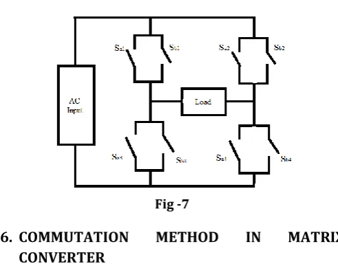
Single Phase Matrix Converter
Fig -7
6.
COMMUTATION
METHOD
IN
MATRIX
CONVERTER
The commutation has always dynamically controllable. It is important that two bidirectional switches are should not switched on at the same. This result of the capacitor input is short circuit and inductive load is open circuit. We have different types of commutation (with matrix converter) available:
6.1 Dead Time Commutation
The Dead time commutation method is used in the part of inverter. It means that load current go throw anti-parallel diode through the dead time period. Dead time commutation method is useless in the case of matrix converter. At the load side results can be measure with the condition of open circuit.
6.2 Current Commutation based on Multiple Steps
Current Commutation based on Multiple Steps is uses in bidirectional switches. These are consistent in current commutation. It can control the current direction. This commutation technique is helped on the knowledge of output current direction. This technique provides reliable current. The active gate drives the calculated current direction.
7.
SIMULATION RESULT
0 0.1 0.2 0.3 0.4 0.5 0.6 0.7 0.8 0.9 1 0
0.1 0.2 0.3 0.4 0.5 0.6 0.7 0.8 0.9 1
Fig -8: P.U. Voltage at load point, with three phase fault, without DVR
0 0.1 0.2 0.3 0.4 0.5 0.6 0.7 0.8 0.9 1 0
0.1 0.2 0.3 0.4 0.5 0.6 0.7 0.8 0.9 1
Fig -9: P.U. Voltage at load point, with three phase fault
8. CONCLUSIONS
The modeling and simulation of Dynamic voltage Restorer (DVR) are presented by the usage of MATLAB/ SIMULATION. The simulation shows the satisfactory performance of DVR in The case of voltage sag and swell. Simulation result ma shows effective custom power of voltage sag and swell. The simulation carried out the better voltage regulation capability of DVR. Dynamic voltage Restorer (DVR) is handling both balanced and unbalanced position without any problem.
The main advantage of DVR is consider To be efficient result has been provided with low cost, fast response, compact size and its control is simple. As a result This DVR model can use to restore load voltage in The case of balance and unbalance condition of voltage sags and swells.
ACKNOWLEDGEMENT
© 2017, IRJET | Impact Factor value: 5.181 | ISO 9001:2008 Certified Journal | Page 1500
REFERENCES
[1] C. Benachaiba, S. Dib O. Abdelkhalek, B. Ferdi. Voltage
quality improvement using DVR.
[2] IEEE Std. 1159-1995. Recommended Practice for
Monitoring Electric Power Quality.
[3] J.G. Nielsen, M. Newman, H. Nielsen and F. Blaabjerg.
2004. Control and testing of a dynamic voltage restorer (DVR) at medium voltage level. IEEE Trans. Power Electron. 19(3): 806 May
[4] T. Devaraju, V.C. Veera Reddy, M. Vijaya Kumar
performance of DVR under different voltage sag and swell condition
[5] B.H. Li, S.S. Choi, D.M. Vilathgamuwa, “Design
Considerations on the Line-Side Filter Used in the Dynamic Voltage Restorer”, IEE Proc. Gener. Transmission Distrib., Issue 1, Vol. 148, pp. 1-7, Jan. 2001.
[6] M. N. Tandjaoui, C. Benachaiba, O. Abdelkhalek
Mitigation of voltage sags/swells unbalanced in low voltage distribution systems
[7] A. Imam, T. Habetler, R. Harley and D. Divan, “Condition
monitoring of electrolytic capacitor in power electronic circuits using adaptive filter modeling,” IEEE 36th Annual Power Electronics Specialists Conference, 2005, pp. 601-607.
[8] B. Wang and G. Venkataramanan, “Dynamic Voltage