CI
l I I
I
c
Technical Newsletter
File No. 1440-01Re: Form No. A24-3117-0
This Newsletter No. N24-0219
Date: June 15, 1964
Previous Newsletter Nos. NONE
Replacement pages for Miscellaneous Input/Output Instructions, ruM 1440 Data Processing System, Form A24-3117-0.
To bring your publication up to date, please replace the following pages with the corresponding pages attached to this Newsletter. Changes are identified by a ver-tical line at the left of the affected text and a dot (.) at the left of an affected figure.
Pages
21 and 22 23 and 24 31 and 32 33 and 34 35 and 36
File this Newsletter at the back of the manual. It will provide a reference to changes, a method of determining that all amendments have been received, and a check for determining if the bulletin contains the proper pages.
The last page of the Technical Newsletter is a Reader's Survey included for your comments regarding this manual (A24-3117-0). We solicit your participation in this survey so that we can attain our goal of providing you with publications of the highest quality. If you wish to complete the survey later, it may be inserted in the manual follOWing page 44. When mailed in the United States, no postage is required.
International Business Machines Corp., Product Publications Dept., Endicott, N. Y.
:0
c
IBM 1442 Card Read-Punch
This section describes the instructions the IBM 1440 Data Processing System uses to control the: IBM 1442 Card Read-Punch, and the IBM 1442, Model 4, Card Reader. The IBM 1442, Model 4, Card Reader operates under the control of the same read and stacker instruc-tions as the IBM 1442 Card Read-Punch.
The data How for the IBM 1442, Model 4, Card Reader is the same as the read operation on the IBM 1442 Card Read-Punch.
Data Flow
The card path and data How for the IBM 1442 Card Read-Punch (Figure 31) is shown in Figure 32. The cards are placed in the 1,200-card capacity hopper face down, 9-edge first. The first card cycle moves the card from the hopper to the read station where it is regis-tered at column zero. During the second card feed cycle, the card is fed to the reading station by a READ CARD instruction. This operation causes each card col-umn to be read twice as the card moves by the reading station column-by-column.
During read cycle 1, the punched-card code for a column is translated to BCD code and stored in core-storage positions specified by the B-address of the READ CARD instruction. On read cycle 2, the punched-card code for the same column is read a second time. The resultant BCD-coded character from the second reading is compared to the BCD-coded character read
Figure 31. IBM 1442 Card Read-Punch
...
Readout 1
Optional Stacker (Standard on Model 2)
Core Storage
" : Readoa' 2
I
CheckTranslation Circuitry
:
Readout During Read Cycle 2I Read -Back Read Cycle 1
I I
I Read Cycle 21
Punch Station Read Station
Figure 32. IBM 1442 Card Read-Punch Data Flow
into storage from the first read cycle. If no error is de-tected, the process continues for each column until a group-mark with a word-mark is detected at the end of the B-field.
After the read operation is completed, the card is registered in column 1 at the punch station.
During the third card-feed cycle, which is started by a PUNCH AND FEED instruction, the BCD-coded charac-ters to be punched are read from core storage, trans-lated to punched-card code, and punched column-by-column into the card at the punch station.
A second core-storage readout cycle occurs that com-pares the BCD characters in storage to the BCD trans-lation of the punched-card code punched in the card.
If no error is detected, this operation continues for the length of the B-field in storage identified by a group-mark with a word-group-mark.
When the card leaves the punch station, it is car-ried to the stacker by a continuously-moving mecha-nism.
Card
Read-Punch Instruction Format
All card read-punch operations are initiated by a card read-punch instruction. This instruction can initiate different card read-punch operations by using specific characters in certain locations of the actual instruction
[image:3.612.331.570.81.381.2] [image:3.612.73.315.456.728.2]Fonn A24-3117-0 Page Revised 6/15/64 by TNL N24-0219
. . - - - General Mode of Operation M-Move Mode(No word marks
involved}
~--- Operating Input/Output Unit %G - Card Read - Punch
~---Unit Number
1 • - First card read - punch 2. - Second card read - punch
~---B -Address
The first core storage address involved in the operation.
I
d-Modifier Character R-Read Card P - Punch Card G - Punch and FeedX XXX XXX X
Figure 33. IBM 1442 Card Read-Punch Instruction Fonnat
The various parts of the card read-punch instruction and their uses are:
General Mode of Operation
This part of the instruction identifies the operation as a move operation. Word marks will not be moved from the specified core-storage area during punching or reading operations.
Unit Number
This part of the instruction specifies which one of the operating units will be active when there is more than one card read-punch attached to the system.
B-Address
This part of the instruction specifies the first core-storage position that will be involved in the operation.
d-Modifier Character
This part of the instruction specifies the type of opera-tion that will be performed in the card read-punch.
IBM J 442 Card Read-Punch Instructions
Read Card
Instruction Format.
Mnemonic Op Code A-address B-address d-character
R M %Gn xxx R
Function. This instruction is used to transfer data read
at the card read-punch read station into a specified core-storage area.
22
The data punched in card column 1 is translated and stored in the core-storage position specified by the B-address. The rest of the data punched in the card is transferred, column-by-column, into the ad-jacent core-storage positions until a group-mark with a word-mark in core storage is sensed. The number of characters read from the card depends on the B-field length that is established in core storage. The B-field length can be from 1 to 80 positions, plus one position for the group-mark with a word-mark. (The system will hang-up in a read operation with the reader-ready light OFF, if the group-mark with a word-mark is missing.
An end-around check condition occurs when the data record length is longer than the number of core-storage positions from the B-address to the highest-numbered position in core storage. In a sys-tem of 4,000 storage positions, for example, if the input data is 75 characters long, and the B-address is 3980, the first 20 input data characters are read into positions 3980 through 3999, and the remaining 55 characters are read into positions 000 through 054. The storage light on the 1447 console is turned ON to indicate this check condition.
As the card at the read station is .read, any card at the punch station is also being moved at the same speed, and is ejected into the number 1 stacker at the end of the read operation.
Word Marks. Word marks are not affected. A
group-mark with a word-group-mark is needed to end the oper-ation.
Timing.
Modell: T
=
.0111 (LI+
1)+
10+
[15+
1 (LB+
1)] ms.Model 2: T = .0111 (LI
+
1)+
[15+
(LB+
1)] ms.Address Registers After Operation.
I-Add. Reg. A-Add. Reg. B-Add. Reg.
NSI BBB B
+
LB+
1Example. Transfer the data read from card read-punch
1 to the area in core storage labeled RDLIN (0303), Figure 34.
Autocoder
t.
Lobel OPERAND:~
,~
~Q
.
:
Assembled Instruction: M %Gl 303 R
• Figure 34. Read Card
[image:4.617.35.275.72.269.2]c
C'
/Punch and Stop
I nstructi on Format.
Mnemonic Op Code
PS M
A-address
%Gn
B-address d-character
xxx P
Function. This instruction is used to transfer data from
core storage to the card read-punch where it is punched in a card.
The data in the core-storage position specified by the B-address is transferred and punched in the card column registered beneath the punching mechanism. The rest of the data located in the adjacent core-storage positions is transferred, column-by-column, and punched in the adjacent card columns until a group-mark with a word-mark in core storage is sensed. The number of characters punched in the card depends on the B-field length that is established in core storage. The B-field length can be from 1 to 80 positions, plus one position for the group-mark with a word-mark. (Characters in excess of 80 will all punch in column 81 and be lost.) When the punching operation ends, the card movement also ends. No other card movement takes place during a punch and stop operation.
Word Marks. Word marks are not affected. A group-mark with a word-group-mark is needed to end the oper-ation.
Timing.
Modell: T = .0111 (Lr
+
1)+
6.25+
12.5 (Ln) ms.Model 2: T = .0111 (Lr
+
1)+
3.13+
6.25 (LB ) ms.Note. \Vhen a punch and stop operation follows either a read
card or a punch and feed operation, the card at the punch station is registered in column 1, and punching begins in col-umn l. When a punch and stop operation follows another punch and stop operation, the card at the punch station is the card that was punched during a previous operation, and punching begins in the column adjacent to the last column previously punched.
Address Registers After Operation.
I-Add. Jleg. A-Add. Reg. B-Add. Reg.
NSI BBB B+LB+l
Example. Punch the data on card read-punch 1,
be-ginning in the area labeled PCHOUT (0303) and ending with a group-mark with a word-mark (Fig-ure 35).
Autocoder
I.
Label ~perati~_ 151 I ~5 ~o
, 7 5 1 , PC}4,OUT,
Assembled Instruction: ~ %Gl 303 P • Figure 35. Punch and Stop
OPERAND
::
~
Punch and Feed
Instruction Forrnat.
Mnemonic Op Code
P
M
A-Address %GnForm A24-3117-0 Page Revised 6/15/64 by TNL N24-0219
B-address d-character
xxx G
Function. This instruction is used to transfer data from
core storage to the card read-punch where it is punched in a card. When the punching operation ends, the card is ejected from the punch station and selected into a stacker.
The data stored in the core-storage position speci-fied by the B-address is transferred and punched in the card column registered beneath the punching mechanism. The rest of the data located in the ad-jacent core-storage positions is transferred, column-by-column, and punched in the adjacent card col-umns until a group-mark with a word-mark in core storage is sensed. The number of characters punched in the card depends on the B-field length that is es-tablished in core storage. The B-field length can be from 1 to 80 positions, plus one position for the group-mark with a word-mark. (Characters in ex-cess of 80 will all punch in column 81 and be lost.) When the punching operation ends, the card is ejected from the punch station and selected into a stacker.
The card located at the read station advances during this operation also, but the data in the card
is not transferred into core storage. A card from the hopper is also advanced and registered at the read station during the punch and feed operation.
W ol'd Marks. Word marks are not affected. A group-mark with a word-group-mark is needed to end the oper-ation.
Timing.
Modell: T = .0111 (Lr
+
1)+
6.25+
12.5 (LB )+
210# ms.Model 2.' T
=
.0111 (Lr+
1)+
3.13+
6.25 (LB )+
160 ms.#When a punch and feed instruction is initiated, a period of 210 ms will elapse before another card read-punch operation can be executed.
Note. When a punch and feed operation follows either a read
Form A24-3117-0 Page Revised 6/15/64 by TNL N24-0219
Address Registers After Operation.
I-Add. Reg. A-Add. Reg.
NSI BBB
B-Add. Reg.
B
+
LB+
1Example. Punch the data on card read-punch 1,
be-ginning in the area labeled PCHOUT (0303) and ending with a group-mark with a word-mark, and then eject the card (Figure 36).
Autocoder
label OPERAND
:~
~
Assembled Instruction: M %Gl 303 G
• Figure 36. Punch and Feed
Select Stacker
This feature provides a second stacker (special fea-ture) for the IBM 1442, Modell, so that cards can be selected under program control for special applications. The IBM 1442, Models 2 and 4, have two stackers as standard equipment.
Instruction Format.
Mnemonic SS
Op Code
K
d-character 2 or O~
Function. This instruction causes the card at the punch
station to fall into stacker 2. Unless stacker 2 has been selected before the operation that ejects the card (read or punch feed), the ejected card is di-rected to stacker 1.
~NOTE: The d-character for the first card read-punch or card reader installed on the system is designated by 2, and the second card read-punch or card reader installed on the sys-tem is designated by O.
Word Marks. Word marks are not affected.
Timing. T = .0111 (LI
+
1) ms.Address Registers After Operation.
I-Add. Reg. A-Add. Reg.
NSI 2bb
B-Add. Reg. 2bb
Example. Enters selected card into pocket 2 (Figure
37).
Autocoder
label
30
Assembled Instruction: K. 2 Figure 37. Select Stacker
24
OPERAND 4a 45
Card Read-Punch Timing
Modell Card Reading
Card reading on the IBM 1442, Modell, can be done at either 285 or 300 cards per minute (CPM).
285 Cards per Minute
The 285-CPM cycle occurs when the next CARD READ instruction is given during the last 20 ms of a card-read cycle (Figure 38). The clutch is allowed to latch up and the 10-ms clutch-pickup time must take place at the beginning of the next card-read cycle.
The time the system is interlocked during a read operation, when the clutch latches up after each opera-tion, is shown in Figures 38 and 39. This timing for-mula can be consolidated as shown in Figure 39. By using the consolidated formula, the total time avail-able for other processing during one card-read cycle can be found by subtracting the consolidated formula from 210. The bottom portion of Figure 39 shows the approximate processing times available by the number of card columns being read.
300 Cards per Minute
The 300-CPM cycle occurs when the next CARD READ instruction is given before the last 20 ms of a card-read cycle (Figure 40). The clutch remains engaged, and does not latch up. The clutch-pickup time of 10 ms is not needed, and the card-cycle time is reduced to 200 ms, which is equivalent to 300 CPM.
The time the system is interlocked during a card-read operation, when the clutch does not latch up after each operation, is shown in Figures 40 and 41. This timing formula can be consolidated as shown in Figure 41. By using the consolidated formula, the total time available for other processing during one card-read cycle can be found by subtracting the consolidated formula from 200. The bottom portion of Figure 41 shows the approximate processing time available by the number of card columns being read.
Less than 285 Cards per Minute
If the card-reading time and the necessary processing time between card-read cycles exceeds 210 ms, there is a corresponding drop in the number of cards read per minute. The formula to compute the number of cards read per minute is shown in Figure 42. The table in Figure 42 shows the approximate number of cards read per minute when the elapsed time between a given. card column in a card-read operation is at least, or more than, 210 ms later than the same card column in the preceding card-read operation.
o
The punch operation takes only 503 ms. Because the
Rrst 40 columns are being punched, the B-Reld in core storage must be only 40 positions in length. This brings the total time for the entire operation to 713 ms.
As can be seen from these examples, the important consideration is not how many columns are punched, but where the punched columns are in the card. Punch-ing 5 columns in the Rrst 5 columns of the card instead of columns 26-30, for example, results in a faster CPM rate (Figure 57). A CPM rate of 215 results on an IBM 1442, Model 2, when the Rrst 5 columns are punched; a CPM of 102 when columns 26-30 are punched.
IBM 1444 Card Punch
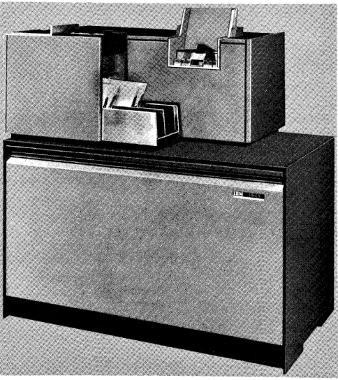
The IBM 1444 Card Punch (Figure 58) provides a high-speed card output to the IBM 1440 Data Process-ing System. This section describes the instructions used with the 1440 system to control the card punch.
IBM 1444 Card Punch Instructions
C
Punch CardInstruction Format.
Mnemonic Op Code A-address B-address d-character
p M %G3 X01 G
Function. This instruction is used to transfer data from core storage into the card punch where it is punched in a card. The data transfer from core storage to the punch ends when a group-mark with a word-mark is sensed.
Word Mal'ks. Word marks associated with the data being transferred are neither considered nor af-fected. The data transfer ends when the group-mark with a word-mark located in core-storage position BOI
+
Ln (length of B-Reld) is sensed.Timing. T = .0111 (LI
+
1)+
I/O ms. I/O equals 240 ms plus punch-access time of 0-60 ms. The process-ing-unit interlock is released after 217.5 ms of the 240-ms punch cycle.Addl'ess Register After Operation.
I-Add. Reg. A-Add. Reg.
NSI BBB
B-Add. Reg.
.B +LB +1
Example. Punoh the data on card punch, beginning
Figure 58. IBM 1444 Card Punch
Autocoder
Label
Form A24-3117-0
Page Revised 6/15/64
by TNL N24-0219
OPERAND
:~
.~
in the area labeled PCHOUT (401) and ending with Assembled Instruction: M %G 3 401 G a group-mark with a word-mark (Figure 59). • Figure 59. Punch Card
[image:7.624.336.573.310.599.2]I'
Form A24-3117-0 Page Revised 6/15/64 by TNL N24-0219
Select Card in Stacker 2
Instruction Format.
Mnemonic
SS
Op Code
.K
d-character
#
Function. This instruction causes the card that was just punched to be selected into stacker 2 after the next punch operation takes place. (The card just punched must be checked at the punch read station before it can be stacked.)
If
a punch-check condition occurs during the next punch operation, the card is automatically directed to stacker 1.NOTE: This instruction must be issued prior to the PUNCH AND GO or READ CARD instruction that moves the card on through the feed.
Word Marks. Word marks are netiher considered nor affected.
Timing. T = .0111 (Lr
+
1) ms.Address Registers After Operation.
I-Add. Reg. A-Add. Reg.
NSI dbb
B-Add. Reg.
dbb
[image:8.623.38.274.69.438.2]Example. Place the card, just punched, in stacker 2 (Figure 60).
Autocoder label
.
:
Assembled Instruction: .K # Figure 60. Select Card in Stacker 2
IBM J 444 Card Punch Timing
OPERAND
40 45 ~o
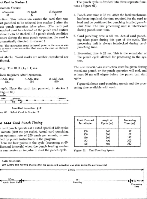
The card punch operates at a rated speed of 250 cycles per minute (240 ms per cycle). Actual card punching, at an optimum rate of 250 cards per minute, is con-trolled by punch instructions in the program.
There are four points in the cycle (occurring at 60-millisecond intervals) when the punch feeding mecha-nism can receive an impulse to start the punch cycle.
CARD PUNCHING
The punch cycle is divided into three separate func-tions (Figure 61).
1. Punch-start time is 37 ms. After the feed mechanism has been impulsed, the time required for the card to feed and be positioned for punching is called punch-start time. The IBM processing unit is interlocked during punch-start time.
2. Card punching time is 181 ms. Actual card punch-ing takes place durpunch-ing this part of the cycle. The processing unit is always interlocked during card-punching time.
3. Processing time is 22 ms. This is the remainder of the punch cycle allotted for processing in the sys-tem.
[image:8.623.53.544.74.736.2]The next PUNCH CARD instruction must be given during this 22-ms period, or the punch operation will end, and at least 60 ms will elapse before the punch can start again.
Figure 62 shows card-punching speeds and the proc-essing time available with each.
Cards Punched Length of Processing Per Minute Cycle (ms) Time (ms)
250 240 22
200 300 82
166 360 142
143 420 202
125 480 262
Figure 62. Card Punching Speeds
250 CARDS PER MINUTE (Assume that the punch card instruction was given during the previous cycle)
I
[image:8.623.38.574.382.719.2]_
240ms~
... Punch Start Time
_-:-37~m_s ~-i
...t .... ---
Punching 181---"'~~111ooI
••
22 m. ProcessingTime
Figure 61. Punch Cycle
32
o
C
'~IBM 1443 Printer
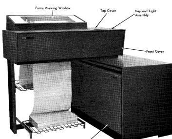
The IBM 1443 Printer (Figure 63) is another output medium for the 1440 system. The number of lines that can be printed per minute depends on the 1443 model and the character set being used. Refer to IBM 1443
Printe1' (Form A24-3120) for details.
Printer Instruction
formatAll printer operations are initiated by either one of two types of printer instructions. If the instruction is two characters long, an operation involving the printer carriage is specified. If the instruction is eight charac-ters long, an operation involving a write operation is specified. The various parts of the printer instruction
(Figure 64) are:
General Mode of Operation
This part of the instruction identifies the operation as either a write operation or a carriage operation. The write operation is performed in the move mode, and any word marks in the specified core-storage area are not moved during the operation.
Forms Viewing Window
Figure 63. IBM 1443 Printer
Form A24-3117-0 Page Revised 6/15/64 by TNL N24-0219
r - - - General Mode of Operation
M - Write Operation in Move Mode (No word marks involved) F - Carriage Operation
~--~---d - Modifier Character
or (See Figure 65)
~ _ _ L..-_ _ _ _ _ Operating Input/Output Unit
%Yl- Printer
~---B - Address
The first core storage address involved in the operation.
j
d - Modifier Character W-Write S - Write and Suppress SpaceX XXX XXX X
Figure 64. IBM 1443 Printer Instruction Format
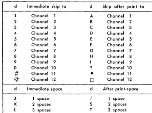
d-Modifier Character
If the instruction is two characters long, the second character is the d-modifier character. This character specifies the type of carriage operation that will occur. Refer to Figure 65 for a list of the d -characters and the carriage operations they initiate.
[image:9.624.331.565.81.274.2] [image:9.624.91.445.421.706.2]Form A24-3117-0
Page Revised 6/15/64 by TNL N24-02l9
d Immediate skip to
1 Channel 1 2 Channel 2 3 Channel 3 4 Channel 4
5 Channel 5
6 Channel 6 7 Channel 7 8 Channel 8 9 Channel 9 0 Channel 10
#
Channel 11 @ Channel 12d Immediate space
J 1 space
K 2 spaces
l 3 spaces
d Skip after print to
A Channel 1
B Channel 2 C Channel 3 D Channel 4
E Channel 5
F Channel 6 G Channel 7
H Channel 8 I Channel 9 ? Channel 10
•
Channel 110 Channel 12
d After print-space / 1 space S 2 spaces
[image:10.624.35.279.75.257.2]T 3 spaces Figure 65. Control Carriage d-Characters
Operating Input/Output Unit
This part of the instruction specifies the printer as the active unit for this operation.
B-Address
This part of the instruction specifies the first core-storage position that will be involved in the operation.
d-Modifler Character
This part of the instruction specifies the type of write operation that will be performed in the printer, when the d-character modifies a write operation code.
IBM 1443 Printer Instructions
Write Line
Instruction Format.
Mnemonic Op Code
W M
A-address
%Y1
B-address d-character
B01 W
Function. This instruction is used to transfer data from core storage to the 1443 printer, where it will be printed.
The high-order position of data in the core-storage position specified by the B-address is transferred and printed in print-position 1. The rest of the data lo-cated in the adjacent core-storage positions is trans-ferred, column-by-column, and printed in the ad-jacent print positions until a group-mark with a word-mark in core storage is sensed.
34
The B-address must always specify one of the
zero one (01) positions in core storage. The number
0,
of characters printed depends on the B-field lengthestablished in core storage. The B-field length can be from 1 to either 120 or 144 positions (24 additional print positions are available as a special feature), plus one position for the group-mark with a word-mark. An automatic single space operation occurs after the actual printing ends unless a different car-riage operation is programmed.
Word Marks. Word marks are not affected. A gtoup-mark with a word-gtoup-mark is required to end the opera-tion.
Timing. T
=
.0111 [( LI+
1)+
384 ~] ms. ~ 120 print positionsNote. An address-validity-check condition occurs if the
B-address specifies the 01 position of the last 100-position block in core storage as well as any starting position other than 01
(unbuffered printer). The system interlocks with the printer light ON.
Addl'ess Registers After Operation.
I-Add. Reg. A-Add. Reg. B-Add. Reg.
NSI %81 B + LB
+ 1
Example. Print the data beginning in the area labeled PRTOUT (0101) and ending with a group-mark with a word-mark (Figure 66).
Autocoder
tperati~
I I I 0 0
W R T O Y T
,~
OPERAND
~o
Assembled Instruction: !:!l %Y1 101 W • Figure 66. Write Line
Write Line and Suppress Space
Instruction Format.
Mnemonic Op Code
WS M
A-address
%Y1
B-address d-clzaracter
BOI S
Function. This instruction is used to transfer data from core storage to the 1443 where it will be printed. The automatic single space, normally taken after printing, is suppressed.
Data in the core-storage position specified by the B-address is transferred and printed in print-position 1. The B-address must always specify one of the zero-one (01) positions in core storage when using
c
an unhuffered printer. The rest of the data located in the adjacent core-storage positions is transferred, column by column, and printed in the adjacent print positions until a group-mark with a word-mark in core storage is sensed. The number of characters printed depends on the B-field established in core storage. The B-field lengths can be from 1 to either 120 or 144 positions (24 additional print positions are available as a special feature), plus one position for the group-mark with a word-mark.
Word "A1arks. Word marks are not affected. A
group-mark with a word-group-mark is needed to end the opera-tion.
Timing. T
=
.0111 [( LI+
1)+
,384 ~] ms. ~ 120 print positionsNote. An address-validity-check condition occurs if the
B-address specifies the 01 position of the last lOa-position block in core storage as well as any starting position other than 01 (unbuffered printer). The system interlocks with the printer light ON.
Address Registers After Operation.
I-Add. Reg. A-Add. Reg. B-Add. Reg.
NSI %81 B
+
LB+
1Example. Print the data beginning in the area labeled
PRTOUT (0101) and ending with a group-mark with a word-mark, and suppress the automatic Single space (Figure 67).
Autocoder
Label ~perati~ lSI 21 5
WSPR.TO~UT
~o 40OPERAND
:S
~Assembled Instruction: M %Yl 101 5
• Figure 67. Write Line and Suppress Space
Control Carriage
Instruction Format.
Mnemonic
CC
Op Code F
d-character
d
Function. This instruction causes the carriage to move
as specified by the d-character. If the d-character is:
1. a digit, an immediate skip to the specified channel in the carriage tape occurs.
2. an alphabetic character containing a 12-zone, a skip to the specified channel in the- carriage tape occurs after the next line is printed.
3. an alphabetic character containing an II-zone, an immediate space operation, as specified by the digit portion of the character, occurs.
Form A24-3117-0
Page Revised 6/15/64 by TNL N24-0219
4. an alphabetic character containing a zero-zone, a space operation, as specified by the digit portion of the character, occurs after the next line is printed.
Refer to Figure 65 for a list of the d-characters and the carriage operations they specify. If the carriage is already in motion when another CONTROL CARRIAGE instruction is given, the stored program execution is suspended until the carriage operation being per-formed is completed. At that time, the carriage action specified by the instruction begins, and the program advances to the next instruction.
Word Marks. Word marks are not affected.
Timing. T = .0111 (LI
+
1) ms+
remaining form-movement time, if carriage is already in motion when this instruction is given. The total form move-ment time depends on the specific carriage opera-tion being performed. Refer to the IBM 1443 Printer Timing section for more detail.Address Registers After Operation.
I-Add. Reg. A-Add. Reg.
NSI dbb
B-Add. Reg.
dbb
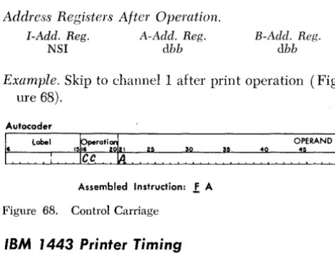
Example. Skip to channell after print operation
(Fig-ure 68).
Autocoder
1
6 label 40
[image:11.617.334.571.336.515.2]Assembled Instruction: ! A
Figure 68. Control Carriage
IBM 1443 Printer Timing
Model 1 Printing Speed
Modell of the lB~[ 1443 Printer operates at a maxi-mum rated speed of 150 lines per minute when the 52-character typehar is installed.
The print cycle is 400 ms long (Figure 69). A total of 368 ms is needed during the 400-ms print cycle to transfer the data from core storage and print it. The form movement takes place during the last 32 ms of the print cycle. Up to two lines of form movement can take place during this time if the delayed forms op is programmed prior to the WRITE instruction. Additional lines (beyond 2) extend the print-cycle time by 10 ms per line. To establish the new line-per-minute rate, divide 60,000 by the print-cycle time (400 ms) to have a 150-ms time for one print line. For information on the additional form-movement timing, refer to the
Form A24-3117-0 Page Revised 6/15/64 by TNL N24-0219
Print Cycle 400ms
Forms
Print Time 368m~ .1 Movement
Figure 69. IBM 1443, Modell, Print Cycle, 52-Character Typebar
NO' ather pracessing can take place during the data-transfer and print time. The entire form-movement time is available to perform ather systems operations.
Model 2 Printing Speed
Madel 2 of the IBM 1443 Printer operates at a maxi-mum rated speed of 240 lines per minute when the 52-character typebar is installed. The duration of the print cycle is 250 ms (Figure 70). A total of 218 ms is needed during the 250-ms print cycle to transfer the data from care storage and print it.
Up to twa lines of form mavement can take place during the narmal print cycle. Additianal lines extend the print-cycle time by 10 ms per line. For informa-tion on the additianal form-mavement timing, refer to the Carriage Speed section.
NO' other processing can take place during the data-transfer and print time. The entire form-movement time (32 ms) is available to perform other systems operations.
Print Cycle 250ms
Print Time 218 ms
Figure 70. IBM 1443, Model 2, Print Cycle, 52-Character Typebar
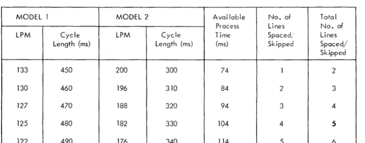
MODEL 1 MODEL 2 Available Process LPM Cycle LPM Cycle Time
Length (ms) Length (ms) (ms)
133 450 200 300 74
130 460 196 310 84
127 470 188 320 94
125 480 182 330 104
[image:12.618.40.357.447.518.2] [image:12.618.44.475.448.724.2] [image:12.618.39.413.574.720.2]122 490 176 340 114
Figure 71. Immediate Forms Space/Skip Operation Timings
36
Carriage Speed
Normal Form-Movement Operation
I
Time 32msForm movement is normally accomplished during the last 32 ms af a print cycle. It is possible to' space two lines during the narmal print cycle, if a DELAYED CON-TROL CARRIAGE instruction is programmed before the WRITE instruction. Each additional line requires an-other 10 ms. This speed is equivalent to' appraximately 15 inches per second.
Immediate Form-Movement Operation
Figure 71 shows various timings that result when an immediate form-movement aperation is specified by the CONTROL CARRIAGE instruction. If the carriage is already in motion when the instruction is given, the stored program execution is suspended until the car-riage operation being performed is completed. At that time, the immediate farm-movement aperation, speci-fied by the instruction, begins. The time required for spacing the first line is 60 ms, and each additional line requires another 10 ms.
Forms .1 Movement
I
Time 32msNo. of Lines Spaced, Skipped
1
2
3
4
5
Total No. of Lines Spaced/ Skipped
2
3
4
5
6
o
.
'("'
.C
c
READER'S SURVEY FORM
Miscellaneous I/O Instructions: IBM 1440 Data Processing System (Form A24-3117-0)
• Is the material: Yes Sat-isfactory No
Easy to read?
0
0
0
Well organized?
0
0
0
Fully covered?
0
0
0
Clearly explained?
0
0
0
Well illustrated?
0
0
0
• How did you use this publication?
As an introduction to the subject
0
For additional knowledge of the subject
0
• Which of the following terms best describes your job?Customer Personnel IBAI Personnel
Manager
0
Customer Engineer0
Systems Analyst0
Instructor0
Operator0
Sales Representative0
Programmer0
Systems Engineer0
Trainee
0
Trainee0
Other Other
• Check specific comment (if any) and explain in the space below:
(Give page number)
0
Suggested Change (Page0
Suggested Addition (Page0
Error (Page )0
Suggested Deletion (Page Explanation:Space is available on the other side of this page for additional comments. Thank you for your cooperation.
A24-3117-0
Fold
BUSINESS REPLY MAIL
NO POSTAGE NECESSARY IF MAILED IN THE UNITED STATES
POSTAGE WILL BE PAID BY . . .
IBM Corporation
General Products Division Development laboratory Endicott, N. Y. 13764
Attention: Product Publications, Dept. 171
Fold
TIrnllir
eInternational Business Machines Corporation
Data Processing Division
112 East Post Road, White Plains, New York
FIRST CLASS PERMIT NO. 170 ENDICOTT, N. Y.
~ -- -~- ···~-~·-~--·I
Staple :
Fold
Fold
I I I I I I I 1
'5 u
:::::
o
c
(II
>
...
/6
o