ABSTRACT
MAHALE, TUSHAR RAMKRISHNA. Electron Beam Melting of Advanced Materials and Structures. (Under the direction of Denis Cormier and Ola Harrysson).
© Copyright 2009 by Tushar Ramkrishna Mahale
Electron Beam Melting of Advanced Materials and Structures
by
Tushar Ramkrishna Mahale
A dissertation submitted to the Graduate Faculty of North Carolina State University
In partial fulfillment of the Requirements for the degree of
Doctor of Philosophy
Industrial Engineering
Raleigh, North Carolina
2009
APPROVED BY:
Harvey West Edward Grant
Denis Cormier
Co-Chair of Advisory Committee
Ola Harrysson
DEDICATION
This work is dedicated to my parents Mr. Ramkrishna Vishnu Mahale & Mrs. Veena Ramkrishna Mahale. Thanks for your patience folks!
BIOGRAPHY
Tushar Mahale was born on the 24th March, 1976, in Mumbai, India. He attended
ACKNOWLEDGMENTS
For their guidance and support, Tushar would like to thanks Dr.Denis Cormier, Dr.Ola Harrysson, Dr.Harvey West, Dr.Edward Grant and Mr.Jason Low
For their patience, support and trust, Tushar would like to thank my parents Mr. Ramkrishna Mahale & Mrs. Veena Mahale, my sister Mrs.Sonali Sohani and the rest of the super extended family
For their inspiration and help, Tushar would like to thank a great group of friends including Cohan Carlos, Parikshit Kulkarni, Kent Meiswinkel, Dr.Ketan Bhatt, Dr. Rajeev Prabhakar, Ron Aman, Kyle Knowlson, Alderson Neira, Bela Bapat; the list goes on.
For lessons on taking a break from work while dangling on rocks, Tushar would like to thank Dr.Hartmut Wege, Hua-Ying Ling, Monica Cu, David Kaplan Tim Ehlich, Lisa Yuan
For a home away from home, Tushar would like to thank the local coffee shops, Global Village, Cup-a-Joe, Helios, Café Driade
TABLE OF CONTENTS
LIST OF TABLES... xi
LIST OF FIGURES ...xiii
Chapter 1 Introduction ... 1
1.1 Background... 1
1.2 Rapid Prototyping... 2
1.2.1 Laminate Based Metal RP Systems... 2
1.2.2 Binder Based Processes ... 4
1.2.3 Direct Metal Melting Processes... 8
1.3 ARCAM Electron Beam Melting (EBM) Process... 11
1.3.1 ARCAM S12 Hardware... 11
1.3.2 System Calibration... 14
1.3.3 ARCAM S12 Control Software and Process Parameters ... 16
Chapter 2 Electron Beam Melting of GRCop-84... 20
2.1 Introduction ... 20
2.2 Literature Review ... 22
2.3 Electron Beam Manufacturing of GRCop-84... 23
2.4 Results ... 30
2.4.1 Chemical Composition of EBM GRCop-84 Samples ... 30
2.4.2 Mechanical Properties of EBM GRCop-84 Samples ... 31
2.5 GRCop-84 Conclusions... 35
Chapter 3 Electron Beam Melting of γ-Titanium Aluminide... 37
3.1 Introduction ... 37
3.2 Background... 39
3.2.1 Literature Review ... 39
3.2.2 Previous Research at North Carolina State University... 45
4.1 Fabricating Al-2024 on the EBM S12... 61
4.2 Non-Stochastic Al-2024 Foams... 80
4.3 Conclusion ... 83
Chapter 5 Electron Beam Melting of Metamaterials... 84
5.1 Introduction ... 84
5.2 CAD Issues ... 87
5.3 Metal Foams ... 89
5.4 Manufacture of Non-Stochastic Metal Meshes on the EBM... 92
5.4.1 Mechanical Testing of Non-Stochastic Foams ... 94
5.4.2 Cryogenic Testing of EBM Manufactured Non-stochastic Foams... 103
5.5 Conclusion ... 118
Chapter 6 Other Materials Developed using the Arcam EBM System... 121
6.1.1 Copper ... 122
6.1.2 7075 and 6061 Aluminum Alloys ... 124
Chapter 7 Modeling the Electron Beam Melting Process ... 144
7.1 Understanding Electron Beam Layered Manufacturing... 147
7.1.1 Causes of “Smoke” ... 148
7.1.2 Melting cycles... 154
7.2 Simulation... 165
7.2.1 Finite Elements Method... 165
7.2.2 Finite Difference Method ... 172
Chapter 8 Conclusion ... 182
LIST OF TABLES
Table 2-1 Properties of GRCop-84... 21
Table 2-2 ICP Elemental Analysis of Alloying Elements for GRCop-84... 31
Table 3-1 Selected material properties for TiAl and nickel superalloys [43]... 38
Table 3-2 ICP elemental analysis results (NSL and NCSU Combined Results)... 48
Table 3-3 ICP results of chamber-deposited metallic film... 49
Table 4-1 Properties of aluminum alloy 2024 ... 56
Table 4-2 Initial Al-2024 EBM test observations... 63
Table 4-3 Small Sample Build Observations for Al-2024... 65
Table 4-4 Processing conditions for Al-2024 test specimens... 69
Table 4-5 Density and porosity in Al-2024 specimens ... 71
Table 4-6 UTS comparison of as-processed and aged Al-2024 specimens... 78
Table 5-1 Summary of lattice compression test results ... 99
Table 5-2 Dimensions of samples for conductivity tests... 107
Table 5-3 Top Temperature for each sample... 110
Table 5-4 Observations on the effect of radiant heat... 117
Table 6-1 Key physical properties of pure titanium, aluminum & copper... 122
Table 6-2 ICP analysis of EBM processed samples of Aluminum alloy 7075 ... 126
Table 6-3 Summary of EDS results for “Black” 7075 aluminum alloy powder ... 128
Table 6-5 EDS results of reused 7075 alloy powder ... 130
Table 6-6 EDS analysis on the “Blobs” formed during the melting of 7075 alloy ... 132
Table 6-7 Composition of JSC-1 lunar regolith simulant... 138
LIST OF FIGURES
Figure 1-1 Laminated metal transformer cores ... 3
Figure 1-2 Conventional 3D printing process ... 5
Figure 1-3 Fused Deposition Modeling (FDM) ... 6
Figure 1-4 Selective Laser Sintering (SLS)... 7
Figure 1-5 Droplet based net-form fabrication... 9
Figure 1-6 Schematic diagram of the Arcam S12 system (Drawing not to scale) ... 13
Figure 1-7 Scanning parameters for the EBM process... 17
Figure 2-1 GRCop-84 powder with Cr2Nb particles dispersed in a copper matrix... 22
Figure 2-2 GRCop-84 hourglass samples fabricated via EBM ... 25
Figure 2-3 Micrographs of EBM-processed GRCop-84 ... 25
Figure 2-4 Heating strategies for influencing microstructure of GRCop-84... 26
Figure 2-5 Current and Speed Vs. Part Height for Various Speed Functions and Layer Thicknesses... 29
Figure 2-6 Graph of 0.2% offset yield stress for GRCop-84... 32
Figure 2-7 Elongation at UTS versus temperature for GRCop-84... 33
Figure 2-8 UTS as a function of temperature for GRCop-84... 34
Figure 2-9 Low Cycle Fatigue (LCF) test results for GRCop-84... 34
Figure 3-1 Typical γ-TiAl processing methods[43] ... 40
Figure 3-3 Ti6Al4V turbocharger compressor wheel fabricated via EBM ... 46
Figure 3-4 Illustration of balling in TiAl sample ... 47
Figure 3-5 Successful EBM TiAl test specimen... 47
Figure 3-6 Initial results of reaction synthesis of TiAl via EBM ... 52
Figure 3-7 XRD plot for selectively reaction synthesized titanium aluminide ... 53
Figure 4-1 Configuration for initial feasibility testing of Al2024 ... 62
Figure 4-2 Configuration for small sample tests of Al 2024 ... 64
Figure 4-3 Surface roughness of initial Al-2024 specimens ... 66
Figure 4-4 ASTM E-8 tensile test specimen dimensions in millimeters ... 67
Figure 4-5 Effect of scan length on Al-alloy 2024’s surface finish ... 68
Figure 4-6 Photographs of Al-2024 Test Specimens... 70
Figure 4-7 Sample I-I with UTS of approximately 21.25 MPa... 72
Figure 4-8 Sample I-II with UTS of approximately 11.25 MPa... 73
Figure 4-9 Sample II-I with UTS of approximately 10MPa... 73
Figure 4-10 Sample II-II with UTS of approximately 325MPa and elongation of 1.57% ... 74
Figure 4-11 Sample I-I Aged, UTS approximately 42.5MPa... 76
Figure 4-12 Sample I-II aged, UTS of approximately 187.5MPa ... 76
Figure 4-13 Sample II-I aged, UTS of 11.5MPa ... 77
Figure 4-16 Aluminum Mesh Load Vs. Displacement Test Results... 82
Figure 5-1 Negative refractive index materials developed using a C-ring resonator .... 85
Figure 5-2 An ordered structure similar to a 3D photonic crystal... 85
Figure 5-3 Examples of stochastic and non-stochastic foams ... 86
Figure 5-4 Grid generated using Hyperfun... 88
Figure 5-5 Discrete constrained stochastic mesh structure... 89
Figure 5-6 Stochastic copper foam... 91
Figure 5-7 Top, front, and dimetric views of hexagonal lattice structures... 94
Figure 5-8 Influence of beam angle, beam thickness, and layer thickness on bonding between layers ... 95
Figure 5-9 Range of strut qualities ... 95
Figure 5-10 Lattice compression test orientation convention... 97
Figure 5-11 Compression test results for 4mm structures with maximum loading up to 1300 lbs ... 97
Figure 5-12 Compression test results for 5mm structures with maximum loading of up to 550 lbs ... 98
Figure 5-13 Lattice compression test results for 6mm structures... 98
Figure 5-14 Compressive strength and elastic modulus versus relative structure density ... 101
Figure 5-15 Lattice structure flex test setup ... 102
Figure 5-17 Micrographs of EBM fabricated lattice beams (a) 100x, (b) 200x ... 107
Figure 5-18 Test samples (a) Sample 1 (b) Sample 2 (c) Sample 4 ... 108
Figure 5-19 Setup of the experiment with sample 1 mounted to aluminum blocks and cryocooler... 110
Figure 5-20 Bottom block temperature vs. applied power ... 111
Figure 5-21 Conductivity Vs. Temperature for Ti6Al4V alloy... 112
Figure 5-22 Temperature profiles from CosmosWorks (a) Sample2 (b) Sample 3 ... 113
Figure 5-23 Heat flux results from CosmosWork ... 114
Figure 5-24 Scanning Electron Micrographs of lattice structure reveal particles sintered to the lattice structures; this increases the effective surface area of the part. ... 116
Figure 5-25 Total power Vs. Temperature with approximate curve fitting ... 117
Figure 5-26 Negative Poisson's Ratio Materials Built On the EBM ... 120
Figure 6-1 EBM processed pure copper ... 123
Figure 6-2 Cracks in EBM processed 7075 a) Micrograph taken parallel to the E-beam scan direction b) Micrograph taken perpendicular to the E-beam scan direction c) top-view of the sample ... 125
Figure 6-3 SEM image of “Black” 7075 aluminum alloy powder ... 128
Figure 6-4 A closer look at a “Black” 7075 powder particle ... 129
Figure 6-7 “Blobs” formed during the melting of 7075 alloy powder ... 131
Figure 6-8 SEM images of E-Beam scans on a 7075 aluminum plate ... 133
Figure 6-9 Comparison’s between Mechanically Alloyed Powder & Pre-alloyed Powder of 7075 a) Mechanically Alloyed b) Prealloyed ... 135
Figure 6-10 Optical micrograph of EBM processed 6061 with Fe-Al intermetallic.... 137
Figure 6-11 Ball milled aluminum regolith mixture with 20% aluminum loading... 139
Figure 6-12 Sintering of a single layer of pure aluminum via low current heating... 140
Figure 6-13 EBM processed JSC-1 lunar regolith simulant with 50% aluminum melted at 60KV acceleration voltage a) Top surface of EBM processed part b) Close up revealing regolith embedded in aluminum matrix ... 141
Figure 6-14 100% JSC-1 Lunar regolith stimulant fixture sintered using the EBM process... 142
Figure 7-1 Electron beam interaction with substrate... 146
Figure 7-2 Type I particle charging... 149
Figure 7-3 Type II particle charging... 153
Figure 7-4 Monte Carlo simulations of beam & substrate interactions[119] ... 155
Figure 7-5 Influence of powder density on charging ... 158
Figure 7-6 Angle of incidence of an electron beam ... 161
Figure 7-8 Relationship between backscattering coefficient and the angle of incidence
of an electron beam... 163
Figure 7-9 Interaction between spherical powder used in EBM processing and the electron beam... 164
Figure 7-10 Simulation of the initial heating of a Start plate embedded in a bed of Aluminum Powder ... 166
Figure 7-11 Arcam AB’s model for electron beam melting... 167
Figure 7-12 Variable density mesh generated along the circular path ... 168
Figure 7-13 Beam scan path over a region meshed to uniform density ... 170
Figure 7-14 Simulation of e-beam scanned over 7075 powder carried out in COMSOL® by breaking down the part into voxels to facilitate the tracing of the beam. ... 171
Figure 7-15 High speed electron beam scan paths during sintering... 173
Figure 7-16 A discretized slice file (SLC)... 175
Figure 7-17 Profile of an electron beam scanning over homogenous low thermal conductivity material. Effect of radiant heat loss has been ignored ... 177
Figure 7-18 Approximating level of sintering... 179
Chapter 1
Introduction
1.1
Background
In 2003, North Carolina State University (NC State) acquired the first, Arcam EBM S12 machine in North America. This gave NC State the opportunity to be integrally involved in process development and optimization from its early stages. In subsequent years, the team has initiated or been directly involved in several new material research projects for the EBM.
During experiments related to new material development, the failure of a build experiment meant repeating the experiment from the beginning and the loss of time due to part cool down and machine clean up. Secondly, part failure is a discrete event; i.e., the means of measuring the extent of success or failure of the part built, and any corrective action needed was based completely on the operator’s subjective experience and “reflex action”.
1.2
Rapid Prototyping
In the early 1990s, freeform fabrication of metals became a focus for a large portion of the additive manufacturing research community. One of the main applications that researchers desired was the development of production tools via near net fabrication. With these tools available to them, researchers would reduce build lead-time and reduce cost building and reworking tools.
The trends in the development of metal-based Rapid Prototyping (RP) systems took three different routes as listed below:
• Laminate based metal RP systems
• Binder based processes
• Direct metal melting processes
1.2.1 Laminate Based Metal RP Systems
Laminate based RP systems involve two separate processes: (1) the cutting of 2D laminates and (2) the stacking and joining of the cut sections. This technology was popularized within the RP community by a manufacturer named Helisys, that marketed the technology specifically for pattern makers from the casting industry.
be cores of transformers that are made by joining metal laminates. What distinguishes the old laminates based manufacturing with rapid prototyping systems is the automation and integration of the cutting and joining steps[1].
Figure 1-1Laminated metal transformer cores
Numerous researchers throughout the 1990s experimented with developing a laminate based layered manufacturing systems to make production tools[2, 3]. What distinguished these new systems from the old laminate based manufacturing was the automation and integration of the cutting and joining processes.
Himmer et al [3] developed a system that cut the laminates using a CO2 laser. The cut
remove any built up edges and to finish the part to the desired surface finish requirements.
Kong et al [4, 5] developed a process called Ultrasonic Consolidation for ultrasonically fusing precut sheets of metal using ultrasonic welding.
The obvious limitation of laminate based component manufacture is its limited ability to produce overhanging regions and the anisotropic strength characteristics exhibited by the parts built by this method.
1.2.2 Binder Based Processes
After the commercial acceptance of the polymer and ceramic-based RP systems, researchers experimented with adapting the existing process technology for manufacturing metal parts.
demonstrated the use of this technology for producing dies for forging Al-7075 components.
Figure 1-2 Conventional 3D printing process
Fused Deposition Modeling (FDM), a commercial system, continuously extrudes and lays down a thermoplastic filament from a base stock of the same thermoplastic wire but with a larger diameter. The process was adapted to deposit green metal and ceramic parts by compounding the metal or ceramic powder with a thermoplastic binder and then extruding it to form the base stock wires that would be accepted into the FDM system [10, 11]. Dense metal or ceramic parts were obtained via sintering and infiltration of the green parts in a furnace.
Greulich et al [12] have come up with an adaptation of the FDM system that uses powder rather than wires to directly make dense metal parts. Dense metal parts are limited to low melting point alloys and the use of a binder-based system was suggested for alloys with a higher melting point.
Figure 1-3 Fused Deposition Modeling (FDM)
The selective laser sintering (SLS) process was developed at the University of Texas at Austin and was later commercialized by DTM Corp. The early models of the system used low power lasers (10W-20W) to selectively sinter a variety of thermoplastic polymers.
Extrusion Head
Supports
Figure 1-4 Selective Laser Sintering (SLS)
Research in the field of adapting this process for manufacturing tooling inserts started with the use of polymer coated (polyamide) metal powder [13, 14]. The nylon on the powder acted like a binder when it was melted by a laser to form a green part. The green part was then passed through the standard processes of binder burn out, sintering and infiltration to form tool inserts.
Later process improvements upgraded the laser to anywhere between a 70W-1000W to directly achieve sintering of the metal powders. The new build themes varied from manufacturing parts with dense skins and sintered insides to making fully dense parts. Some processes used a two-phase powder system consisting of one low melting point and one high melting point metal. Similar to the polymer binder; the low melting point metal acted like a binder for making a green part of the high melting point metal [14-21].
Laser Scanning Mirror
Powder Feed Roller
Eoplex Technologies Inc. has developed a process called High Volume Print Forming (HVPF) capable of making heterogeneous parts in metals, ceramics and polymers [22, 23]. The process builds parts via screen-printing layers of engineered inks. The ink consists of metal or polymer particles suspended in a photopolymer. It is possible to selectively print inks of different materials within a single layer. The layers are assembled to form a green part followed by burn out and sintering operations to generate the finished item. High print resolution and capabilities to manufacture across a large range of materials in a single part makes this process attractive. The limitations are the very large size of the machine and the need for a high volume production.
1.2.3 Direct Metal Melting Processes
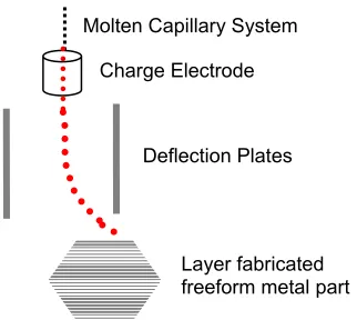
Figure 1-5 Droplet based net-form fabrication
A combination of additive and subtractive fabrication called Shape Deposition Manufacturing (SDM) was developed at Carnegie Mellon University [31, 32]. The process progresses in the following steps:
• Deposition of material using an appropriate welding method
• 5-axis CNC machining of the slice using first order shape approximation for the slice
• Shot peening for stress relief
The process was adapted for manufacture of heterogeneous materials as well as making meso-scale dense metal parts. One of the challenges with this process is the possibility of tool gouging into the previous layer while 5-axis machining of surfaces at an acute angle to the X-Y plane. The current research of this group focuses on adapting the technology for making fuel cells and tissue scaffolds. A number of variants of this process have been developed at various research groups.
Molten Capillary System
Charge Electrode
Deflection Plates
Laser melting has been one of the most widely used techniques for direct freeform fabrication of dense metal parts. The direct adaptation of the commercial selective laser sintering processes (liquid phase sintering) is one example of laser based processing of metals.
The direct fabrication of a part in a bed powder poses three problems
• The powder in the immediate neighborhood of the melted region sinters and melts to the part causing an uneven surface finish (this is also seen in the Electron Beam Melting process)
• The presence of loose powder around the melt region makes it difficult to model the melting process as the radiated heat loss from the powder becomes a parameter of uncertainty.
• The melting of metal requires an inert atmosphere around it to prevent contamination or oxidation of the powder. This is done by: (1) A localized shroud of inert gas around the melt pool, or (2) having the entire build envelope in an inert atmosphere. The jet of inert gas being delivered at the metal laser interface blows away the powder from the bed.
1.3
ARCAM Electron Beam Melting (EBM) Process
Arcam’s S12 EBM system[36] is the first commercial electron beam based layered manufacturing system designed for producing dense freeform metal parts. The important aspects of the hardware and process variables that could have a significant effect on the processing of parts are briefly described here. The hardware and software configurations described in this document are the earliest configurations for the Arcam AB’s S12 system. The machine continuously goes through hardware and software upgrades as part of the maintenance contract.
1.3.1 ARCAM S12 Hardware
The system can be broken down into the following hardware components:
Build Chamber
The fabrication of the part actually happens in the build chamber. The chamber also houses almost all the mechanical components of the system including the build tank, powder feeders and raking systems.
Build Tank
Powder Feeder & Raking system
The powder is stored inside two hoppers located in the top left and right corners of the build chamber. The raking system picks up a calibrated dose from the two hoppers and spreads a thin uniform layer over the bed of powder in the build tank (refer Figure 1-6). The rakes that carry out the powder spreading are disposable and are made out of thin sheets of spring steel.
Control System
The control system consists of a computer, programmable logic controller, signal amplifier and a set of DC power supplies.
High Voltage Power Supply
The high voltage power supply located at the bottom of the control cabinet. It provides power to the following components (refer Figure 1-6):
• Heating the filament
• Grid cup-filament bias voltage
• Acceleration voltage for the electrons
Vacuum System
--
High Voltage Supply + Grid Cup
Tungsten Filament
Anode & Drift Tube
Bias Voltage Regulator
Astigmatism Coils
Focus Coils Gun Chamber
Deflection Coils Electron
Beam
Powder Hopper
Rake
Start Plate
Part
Build tank
Build Chamber
Electron Beam Column
The electron beam column consists of a cathode assembly, a drift tube-anode assembly, focus coils, astigmatism coils and deflection coils.
The cathode assembly consists of a tungsten filament based cathode and a grid cup. The tungsten filament is electrically heated to the point where the tip of the filament is white hot. A potential difference between filament and the anode, accelerates electrons from the filament towards the anode. The electrons that are not absorbed by the anode pass through the drift tube and eventually interact with the part.
A negative bias on the grid cup with respect to the filament controls the amount of electrons that finally reach the anode (and eventually the processed part).
The cross sectional geometry of the beam is controlled by the focus coils and the astigmatism coils. The position of the beam over the surface of the part in the build plane is controlled by a set of deflection coils [36].
1.3.2 System Calibration
Rake Calibration
A calibrated rake accurately controls the amount of powder that is being dispensed from the powder feeders into the build plane. When too little powder is dispensed it leads to an uneven distribution or lack of powder across the build plane. An excess of dispensed powder leads to shortage of powder in the later layers of the build. Another consequence of excess dispensing is the spillover of the powder from the rack back onto the build plane. This leads to the development of non-uniform layer thickness that can eventually lead to the development of “smoke” during the processing of that particular layer.
Beam Calibration
1.3.3 ARCAM S12 Control Software and Process Parameters
Similar to conventional RP systems, Arcam’s S12 systems use sliced data in the form of a file format called SLC. The SLC file defines the geometry of individual two dimensional cross-sections and the distance between two adjacent slices.
As stated earlier in section 1.3, the build process begins with the heating of a build plate of a compatible material to a suitable temperature. Once the plate is heated to a predetermined temperature, the system progresses with the building of the actual part.
Multiple SLC files can be run concurrently to define various processing conditions within a given build layer. The most important amongst these are themes (sets of process settings) for:
• Preheating and sintering the entire build region. This is for (1) minimizing thermal gradient and hence the internal stresses within the part and, (2) providing conductivity paths for the incident electrons before the beginning of a melt cycle.
• Sintering of powder in the regions located below overhangs. Higher sintering provides (1) additional mechanical support to overhanging sections and, (2) higher conductivity for the electrons from the electron beam to flow out of the powder bed.
For the sake of nomenclature, the first three of the files processed by the system have been allocated by the Arcam Control software as “Preheating files” or “phd files”. Up to two additional files are allocated as “Postheating files” or “pod files”. One file is meant specifically for defining the actual melting parameters. The precedence of executing the files for any given layer is preheating -> melting -> postheating.
Each of these files [37] contains contour and inner raster features. The contours are defined by the perimeter for that layer and up to five concentric offsets of the perimeter can be used. The inner raster patterns used to melt the bulk of the part look similar to that shown in the figure 1-7.
Line Offset Raster
Patterns
Contours
Layer Perimeter
Offset to contour
The process parameters of the preheat and postheat files can be defined manually. There are close to 25 parameters in each of the preheat and postheat files. The main parameters include:
• Minimum and maximum beam current, and the number of times the beam scan is to be repeated. The beam current is ramped linearly from the minimum to the maximum beam current during every scan
• Scanning speed of the electron beam
• Distance between individual scan lines (referred to as line offset)
• Line order for the hatch pattern.
This body of work shall examine the role these process parameters play in the development of new materials using Arcam AB’s Electron Beam Melting System.
1.4
Conclusion
The Electron Beam Melting (EBM) process has distinct advantages over the existing methods used for fabricating fully dense metal parts
• The high vacuum atmosphere necessary to process a part using the EBM minimizes the possibility of part contamination due to any rogue gases within the build envelope.
a laser, an electron beam consists of electrons of finite mass that are moving at a high velocity and transfer their energy to the processed material through their impact with the material. The electrons travel deep into the material as they transfer their kinetic energy to other electrons within the material.
• The electron beam in Arcam’s S12 EBM system is controlled by magnetic deflection coils. This reduces the number of moving parts in the EBM system while simultaneously permitting the electron beam scans to achieve speeds as high as 40,000 mm/s. The large scan speeds aid in increasing the build speeds while simultaneously opening the possibility of controlling the microstructure evolution within a part.
Chapter 2
Electron Beam Melting of GRCop-84
2.1
Introduction
Cu-8Cr-4Nb (GRCop-84) is a dispersion strengthened copper-based alloy developed by researchers at NASA's Glenn Research Center in the 1990's. The chromium and niobium exist in the form of intermetallic Cr2Nb in a matrix of copper. The dispersion of small
intermetallic particles (roughly 0.1-10μm) inhibits the grain growth in copper. At low temperatures, small grain boundaries act as barriers to dislocations, thus strengthening the material. The stability of Cr2Nb particles at elevated temperature prevents the loss of
strength of the alloy at high temperature. The Hall and Petch relationship explains the relationship of the grain size to part strength.
d
k
y oy=
σ
+σ
where σy is the yield strength, σo is the frictionless stress resistance, ky is the Hall-Petch
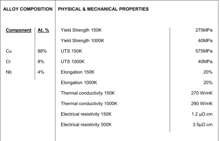
Table 2-1 Properties of GRCop-84 ALLOY COMPOSITION Component Cu Cr Nb At. % 88% 8% 4%
PHYSICAL & MECHANICAL PROPERTIES
Yield Strength 150K
Yield Strength 1000K
UTS 150K
UTS 1000K
Elongation 150K
Elongation 1000K
Thermal conductivity 150K
Thermal conductivity 1000K
Electrical resistivity 150K
Electrical resistivity 500K
275MPa 40MPa 575MPa 40MPa 20% 20% 270 W/mK 290 W/mK
1.2 μΩ.cm
3.5μΩ.cm
[38]. It has excellent strength at extreme temperatures while maintaining good creep, low-cycle fatigue lives and low thermal expansion [39].
Figure 2-1 GRCop-84 powder with Cr2Nb particles dispersed in a copper matrix
2.2
Literature Review
Ellis and Keller [39] studied the thermophysical properties of GRCop-84 in comparison with NARloy-Z (cu-3 wt.% Ag-0.5 wt.% Zr) which is currently used as the main combustion chamber liner material. The GRCop-84 had a much lower coefficient of thermal expansion. A lower CTE results in lower thermally induced stresses. Practically speaking, this translates into longer life for the liner. This is obviously desirable for a Reusable Launch Vehicle (RLV).
Ellis [38] provides a broad overview of the GRCop-84 material. In general, rapid solidification processes must be used with the material to prevent Cr2Nb precipitates
from growing in size during solidification. GRCop-84 is most commonly produced in powdered form via argon gas atomization. GRCop-84 has also been by vacuum plasma spraying onto mandrels [42].
2.3
Electron Beam Manufacturing of GRCop-84
The precipitation and agglomeration of Cr2Nb in most conventional casting processes
makes it almost impossible to make parts by any conventional casting process (particularly thick cross sections). The electron beam freeform fabrication process makes it possible to retain the small particle size of Cr2Nb due to the very small size of the weld
Preliminary experiments intended to determine the feasibility of processing GRCop-84 with the EBM process provided the motivation for establishing a less ad-hoc procedure for new material development. A set of parameters called a build theme is suggested for all the materials commercially sold by Arcam. These themes automatically calculate the speed and current requirements for processing the part. The exact method by which these parameters are generated is not completely understood. The parameters that influence the automatic power calculation are the maximum current, the layer cross-sectional area and something called the “speed function” which has discrete values ranging from -10 to 200. The actual relation between this speed function and the speed and current used for processing has not been made available outside of Arcam, but the parameter seems to influence the scanning speed of the electron beam.
Figure 2-2 GRCop-84 hourglass samples fabricated via EBM
Optical micrograph of GRCop-84 specimen produced on the EBM
SEM of GRCop-84 specimen from the EBM clearly showing the Cr2Nb precipitates (white)
Figure 2-3 Micrographs of EBM-processed GRCop-84
smaller region within the melt area of the part was reheated immediately after the melting operation. It was observed that this led to coarser precipitates of Cr2Nb.
Reheating within a melt region
Melt region
Reheat region
Controlled microstructure via detached sprues
Melt region Detached Sprue
Figure 2-4 Heating strategies for influencing microstructure of GRCop-84
For the second experiment; four disconnected sprues of identical cross-sectional area were constructed around a relatively large cross-sectioned part that was being melted. Each of the sprue was melted prior to the melting of the part. This was carried out for every layer of the part. The amount of heating for each sprue was substantially different. It was expected that directional solidification or grain growth would be observed.
processing of the material lead to the generation of finer particles due to vaporization of the material. These finer particles lead to arc trips during the processing of the alloy and on advice from Arcam AB, the experiments with GRCop-84 were halted.
It was decided to carry out simulations using Arcam’s EBM Control software to determine the processing parameters used by the system to melt a uniform cross-sectioned part of 30 mm square. Figure 2-5 shows various plots of current versus speed under different conditions. It was observed that the first few layers of a part are melted with very high currents and speed. This might be due to the fact that the control software uses the history of the previously melted layers while calculating the parameters for the next layer. Since the start plate is modeled into the part file, its mass might be considered to be a sort of a heat sink and hence the reason for high scan speeds and current. The stumbling block here is that key thermophysical properties such as thermal conductivity, melting point, and latent heat of fusion for the material are not considered by the control software.
long as all other variables were equal, the scan speed increased when the speed function was increased.
SF 10 0 5 10 15 20 25 30
0 5 10 15 20 25
Part Heigh mm
C u rre n t m A SF 10 SF 10 0 100 200 300 400 500 600 700 800 900 1000
0 5 10 15 20 25
Part height mm
S p eed m m /s SF 10
(a) Current & Speed Vs. Part Height for constant Speed Function of 10 & layer thickness 0.1mm
Speed Function & Current
0 5 10 15 20 25 30
0 5 10 15 20 25
Part Height mm
Cu
rr
en
t M
A SF1- C
SF2 - C SF5 - C SF10 - C SF20 - C
Speed Function & Scan Speed
0 200 400 600 800 1000 1200 1400 1600
0 5 10 15 20 25
Part Height mm
Sp
ee
d
m
m
/s SF1 - S
SF2 - S SF5 - S SF10 - S SF20 - S
(b) Current & Speed Vs. Part Height for Speed Function 1, 2, 5, 10, 20 & layer thickness 0.1mm
Layer thickness & Current
0 5 10 15 20 25 30
0 5 10 15 20 25
Part Height
Cu
rr
en
t m
A 0.1 - C
0.2 - C 0.3 - C 0.4 - C
Layer thickness & Speed
0 100 200 300 400 500 600 700 800 900 1000
0 5 10 15 20 25
Part Height Sp ee d m m
/s 0.1 - S
0.2 - S 0.3 - S 0.4 - S
(c) Current & Speed Vs. Part Height for constant Speed Function of 10 & layer thickness 0.1, 0.2, 0.3, 0.4 mm
Based on these simulations; it was concluded that there was a need for developing a more robust methods for EBM process parameters that can handle new materials became evident.
2.4
Results
Several specimens produced on the EBM were sent to NASA for testing, and the results of these tests are presented below.
2.4.1 Chemical Composition of EBM GRCop-84 Samples
Table 2-2 ICP Elemental Analysis of Alloying Elements for GRCop-84
Weight % Powder Processed
Cu 87.23 87.55
Cr 6.78 6.55
Nb 6.00 5.90
Total 100.00 100.00
2.4.2 Mechanical Properties of EBM GRCop-84 Samples
It is known that billets of GRCop-84 can be produced via extrusion, and that billets can be machined to a desired shape. However, this processing route is extremely time consuming and costly due to material waste. The EBM process was studied here due to the fact that it is a relatively fast near net shape process. Experiments were carried out to compare as best as possible the material properties obtained during this EBM feasibility study with properties obtained with more conventional methods.
0.0 5.0 10.0 15.0 20.0 25.0 30.0 35.0 40.0
-500 -300 -100 100 300 500 700 900 1100 1300 1500
Temperature (°F) 0. 2% O ff set Y iel d S tress (K S I) As-EBM'd As-Extruded
Figure 2-6 Graph of 0.2% offset yield stress for GRCop-84
0.0 5.0 10.0 15.0 20.0 25.0 30.0 35.0 40.0 45.0 50.0
-500 -300 -100 100 300 500 700 900 1100 1300 1500
Temperature (°F)
E
longa
ti
on (
%
)
As-EBM'd As-Extruded As-HIP'd
Figure 2-7 Elongation at UTS versus temperature for GRCop-84
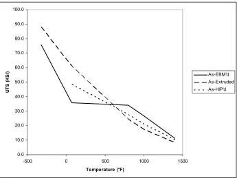
0.0 10.0 20.0 30.0 40.0 50.0 60.0 70.0 80.0 90.0 100.0
-500 0 500 1000 1500
Temperature (°F) U T S ( K SI ) As-EBM'd As-Extruded As-HIP'd
Figure 2-8 UTS as a function of temperature for GRCop-84
0.1 1 10
10 100 1000 10000
LCF Life (Cycles
S tr ain R an g e ( % )
EBM (70 F) EBM (1000 F) Extruded (1112 F) HIP'd (1112 F)
2.5
GRCop-84 Conclusions
This chapter has presented results from an initial feasibility study designed to assess the suitability of using the EBM process to produce complex near net shape GRCop-84 components. GRCop-84 is a relatively costly material that is difficult to cast into complex shapes, hence successful demonstration of an alternate processing route, like the EBM, would represent an important contribution.
Prior to this study, GRCop-84 had never been fabricated using the EBM process. It was therefore necessary to find a set of process parameters that will result in full densification and interlayer fusion. However, in this feasibility study, no attempt was made to iteratively modify process parameters so as to optimize material properties.
Optical and SEM microscopy confirmed that full densification and interlayer fusion were taking place with the given process settings. Furthermore, Cr2Nb particulates were
generally 1 μm or smaller, thus demonstrating that solidification was sufficiently rapid to prevent unwanted growth of Cr2Nb particulates. Chemical analysis also confirmed
minimal loss of alloying elements due to rapid solidification.
temperature applications in mind, it is therefore conceivable that the current process settings are suitable for high temperature applications without any need for further optimization. For cryogenic or room temperature applications, a formal process parameter optimization study would be recommended as the budget allowed.
In conclusion, this study has demonstrated that the EBM process can produce geometrically complex GRCop-84 components to near net shape. Further process optimization for low temperature applications is recommended. The present process settings produce excellent results at elevated temperatures.
Chapter 3
Electron Beam Melting of
γ
-Titanium
Aluminide
3.1
Introduction
Table 3-1 Selected material properties for TiAl and nickel superalloys [43]
Property Conventional Ti
Alloys
Ti3Al TiAl Ni based
superalloys
Density, g/cm3
Modulus GPa
Yield Strength MPa
Tensile Strength MPa
Creep Limit C
Oxidation Limit C
Ductility at RT, %
Ductility at HT, %
4.5 96-117 380-1150 480-1200 600 600 20 High 4.1-4.7 100-145 700-990 800-1140 760 650 2-10 10-20 3.7-3.9 160-176 400-650 450-800 1000 900 1-4 10-60 8.3 206 …. ….. 1090 109 3-4 10-20
3.2
Background
3.2.1 Literature Review
For the proposed study, a freeform fabrication approach to fabricating intermetallics via reaction synthesis will be developed. Intermetallics are ordered alloy phases formed between two metallic elements. The ordered structure results in enhanced strength, stiffness, creep resistance and oxidation resistance at elevated temperature. The intermetallics of titanium have the added benefit of exhibiting low density in comparison to nickel based superalloys, thus making them excellent candidates for aerospace applications [43-49].
Conventional Processing of Intermetallics
Almost all conventional manufacturing processes for intermetallics minimize their dependence on shape manipulation via plastic deformation. Figure 3-1 briefly describes the methods used.
Figure 3-1 Typical γ-TiAl processing methods[43]
Weaver et al [50] have continuously cast thin strips of γ-TiAl. Researchers at Wright-Patterson AFB [51] have processed γ-TiAl through tape casting of γ-TiAl powder mixed with an organic binder. The green casts where later processed by hot isostatic pressing (HIP) to form dense tapes. The green tapes shrunk from 0.9mm thickness to 0.25mm after the HIP process.
Powder Metallurgy (PM) has been widely used for producing titanium aluminides. There are two methods for manufacturing parts via this route. The first involves conventional
Alloy Ingot
HIP homogenize
Alloy powder elemental powder
Consolidate HIP or HP
Billet
Hot Work
Cast Near Net
HIP
Heat NNS
powder metallurgy using compaction, sintering and HIP'ing of prealloyed intermetallic powders [52]. The other route involves the reaction synthesis of elemental powders. Rawers et al [53] used the powder metallurgy route to mildly compact (6.5 MPa) equi-atomic elemental powders of Ti & Al using a graphite die. The graphite die was heated to beyond the melting point of Al with simultaneous hot pressing to initiate the reaction synthesis of the TiAl. It was observed that the proportions of the resulting intermetallics (Ti3Al, TiAl) were a function of the hot pressing conditions (temperature, pressure, heating time).
Bertolino et al [54] studied the ignition mechanisms for Ti-Al and Ti-Ni powder systems by igniting compacts of elemental powders using a CO2 laser. Proportions of the
elemental powders were varied, and the phases of the reacted compacts were observed. They defined the ignition energy (Eig) stored up to the ignition of the pellet as
∫
= ⎥⎦ ⎤ ⎢ ⎣ ⎡ Δ Δ − − − = tigt melt melt emiss conv o ig dt t H Q Q I E 0 α where ig
It was observed that the sample's absorptivity of the laser was very low, varying between 0.038 and 0.17. It was also observed that a reaction of an equi-atomic mixture of the elemental powders (A, B) did not necessarily generate a product of the type AB. The generation of the right type of products requires a fine control over the ignition time and the incident power. Similar laser based reaction initiation techniques have been used for other alloy systems [55].
One of the most common methods of making γ-TiAl components is through casting [56, 57]. In these studies, the casting was carried out using an induction skull melting furnace. All the cast specimens were HIP'd for 4 hrs at 1250°C to remove internal porosity [56]. Some specimens were further HIP'd between 1250˚C and 1350˚C for 24 hrs. It was observed that the constituent α2+γ and γ phases (α2 phase is Ti3Al) as well as the size
Freeform Fabrication of Intermetallics
Freeform fabrication approaches to intermetallic production are based on either the melting of prealloyed intermetallic powders or the reaction synthesis of elemental powders.
Srivastava et al [59-62] have developed a laser-based freeform fabrication process called Direct Laser Fabrication (DLF) that uses a variable intensity CO2 laser (300-450W) to
selectively melt layers of Ti-48Al-2Mn-2Nb powders. It was observed that the grain structure varied between equiaxed and lamellar due to the combined effect of instant quenching caused by the localized melting and laser power. Since the lamellar structure is the most preferred of the grain structures, the samples were post-processed using hot isostatic pressing (HIP), and the effect of the length of the treatment and treatment temperature on the sample microstructure was studied. It was observed that a slow heat and a very low cooling rate led to good lamellar α2+γ titanium aluminide.
Moll et al [63] experimented with Ti-47Al-2Cr-2Nb powder acquired from Crucible research that was selectively melted using a 14 kW CO2 laser. As was the case with
Srivastava's results, they observed that the parts made by this process required post-processing via HIP.
Engineered Net Shaping (LENS) system by Optomec. It was observed that the components that were made using this system contained needle-like or dendritic formations of Ti2AlC in addition to the base constituents. The authors observed that the
parts were susceptible to cracking due to large thermal gradients that the parts were subjected to. Preheating of the substrate was suggested by the authors to prevent cracking of the parts.
Figure 3-2 Selective reaction synthesis via printing of molten Al droplets [45]
A research group in Russia [68] has developed a selective laser induced sintering process for carrying out selective reaction synthesis of a variety of intermetallics. A YAG:Nd laser with power varying between 0.5 and 24W was used to initiate the reaction. This is orders of magnitudes lower than the power needed to process prealloyed γ-TiAl. It was observed that weakly exothermic reactions initiated locally and did not propagate through the rest of the solid.
3.2.2 Previous Research at North Carolina State University
A maker of heavy duty construction equipment contacted the EBM research group at North Carolina State University and expressed an interest in the use of EBM technology for making titanium aluminide components that would maintain good mechanical properties at elevated temperature.
Al Droplet Molten Al
Graphite Cylinder Air Atmosphere
Figure 3-3 Ti6Al4V turbocharger compressor wheel fabricated via EBM
From 2004-2005, industry sponsored TiAl research took place in the form of a multidisciplinary senior design project between the departments of Industrial Engineering and Materials Science and Engineering. The specific composition of γ-TiAl used in this study was Ti-47Al-2Cr-2Nb acquired from Crucible Research. The prealloyed γ-TiAl powder had a particle distribution of -100/+325 mesh (e.g. 45 – 150
that took place for a wide range of process parameters. Figure 3-5 shows a successfully fabricated TiAl test specimens.
Figure 3-4 Illustration of balling in TiAl sample
Figure 3-5 Successful EBM TiAl test specimen
Table 3-2 summarizes the results of all ICP analyses' done. The data indicates that approximately 7.5% of the aluminum vaporized during processing for the processing conditions used to make these bars. The loss of 7.5% Al on the Ti-Al binary phase diagram would lead to a decrease in the amount of γ-TiAl. It is further noted that approximately 0.5% Cr was lost.
Table 3-2 ICP elemental analysis results (NSL and NCSU Combined Results)
Initial Powder EBM Part Element
Weight% Atomic% Weight% Atomic%
Ti 62.50 49.99 65.68 57.03
Al 32.70 46.43 25.18 38.83
Nb 5.01 2.06 5.08 2.27
Cr 2.73 2.00 2.28 1.82
Fe 0.03 0.02 0.05 0.04
chromium – the elements whose concentrations were shown to have been decreased the most in the EBM bars.
Table 3-3 ICP results of chamber-deposited metallic film
Element Weight% Atomic%
Ti 8.98 5.51
Al 83.80 91.28
Cr 5.68 3.21
It was concluded that the low electrical conductivity of the pre-alloyed γ-TiAl caused most of the problems [69]. The long preheating cycle required to prevent charging of the particles and the high melting temperature caused significant vaporization of the Al leading to less than optimal material properties. It was observed that the conductivity of the γ-TiAl powder decreased over time as well, making it even harder to process. This could possibly be due to oxidation of the powder. Electron beam scanning patterns that could assist dielectric breakdown is one approach to overcoming this problem. Similar methods had been tried for spark sintering of titanium aluminides [70].
3.3
EBM Based Combustion Synthesis of Titanium Aluminide
alloyed elemental powders. The SIMTech group has produced γ-TiAl by compacting mechanically alloyed titanium and aluminum powders in molds and heating to 660°C. The reaction is initiated as the aluminum reaches its melting point [67, 71]. The group at SIMTech was looking for ways of processing the γ-TiAl in a more controlled fashion with greater geometric flexibility. It was suggested that an electron beam could be used to induce the reaction synthesis, and SIMTech supplied two types of powders to the research group at NC State University for evaluation. The energy required for carrying out such reaction would be orders of magnitude lower than that used for melting prealloyed powders as shown by Shishkovsky [68].
The two SIMTech powders consisted of equiatomic mixtures of elemental titanium and aluminum powders. The first powder was ball milled to mechanically alloy the two powders. The second powder was merely mixed. Initial feasibility experiments were conducted to test the hypothesis that it was possible to use the energy from the electron beam to induce a contained reaction synthesis.
intended to investigate whether or not the uncompacted powder would ignite if the steel plate was heated to 660°C. The electron beam was scanned over the half of the plate that was not covered with powder in order to slowly raise the temperature of the plate and powder. The beam current was successively increased until a thermocouple attached to the underside of the steel plate read 800°C. No visible reaction of the powder took place at this temperature. In the next experiment, the pocket in the steel plate was filled with powder, and the powder was directly preheated using high scan speeds and a slowly increasing beam power. This was carried out until the reaction was visually identified by a sudden bright glow. A thin layer of titanium-aluminide had formed through reaction synthesis, but there was unreacted powder under the layer of reacted powder (see Figures 3-6c and 3-6d).
(a) Reaction synthesis of titanium alumnide with scan lines 1 mm apart (notice lightly
sintered powder between strands)
(b) Reaction synthesis selectively induced in the top-center portion of the start plate
(c) Distinct edge formation at the boundary of reacted and unreacted powder confirming
controlled reaction synthesis
(d) Reaction propagation perpendicular to the surface of the powder
Figure 3-6 Initial results of reaction synthesis of TiAl via EBM
using a 5 ton hydraulic press and a die matching the pocket. This time the reaction was still controlled but propagated throughout the thickness of the powder.
X-Ray Diffraction (XRD) was used to establish the phases of the uncompacted titanium-aluminide obtained from the reaction synthesis. As can be seen from the XRD plot below, there are still small traces of unreacted titanium and aluminum most likely due to loose powder from the bottom of the sample or due to unreacted powder between beam scan lines.
(Sincere thanks to Prof.J.Kasichainula for help with generating XRD plots)
Figure 3-7 XRD plot for selectively reaction synthesized titanium aluminide
There is a clear peak of TiAl3 at 39.4, but other than that, there is no conclusive evidence
of predominantly γ-TiAl or other phases of titanium-aluminide. This happens for two reasons. First, there is an abundance of liquid Al when the reaction occurs thus making it
400
0 100 200 300 500 600 700
20 30 40 50 60 70
2 Theta
Si calibration peak
TiAl3
Ti Al
easier for the formation of TiAl3. Second, the free energy for the formation of TiAl3 is
lower than that required for the formation of TiAl or Ti3Al [72, 73]. It is apparent that
Chapter 4
Electron Beam Melting of Aluminum 2024
In the past few decades, there is a steady trend of replacing ferrous alloys with aluminum alloys. The main advantages of aluminum alloys are their reasonable strength to weight ratios and their low melting points, which makes them more energy efficient to process. This material also possesses other desirable qualities such as high conductivity, ductility, machinability and toughness. Aluminum alloys also easy to recycle due to their low melting points. Their recycling also requires far less energy than that required for extraction of aluminum from ore. The development of better aluminum casting alloys has resulted in almost a complete migration to aluminum engine blocks in the passenger car markets.
Table 4-1 Properties of aluminum alloy 2024 ALLOY COMPOSITION Component Al Cr Cu Fe Mg Mn Si Ti Zn Other Wt. % 90.7-94.7 Max. 0.1 3.8-4.9 Max. 0.5 1.2-1.8 0.3-0.9 Max. 0.5 Max. 0.15 Max. 0.25 Max. 0.05
PHYSICAL & MECHANICAL PROPERTIES (T-6 tempering)
Density
Tensile Strength, Ultimate
Tensile Strength, Yield
Elongation at break
Modulus of elasticity
Electrical resistivity
CTE, linear 250˚C
Specific heat capacity
Thermal Conductivity Melting Point Solidus Liquidus 2.78g/cc 427MPa 345MPa 5% 72.4GPa 4.49e-006 ohm-cm
24.7μm/m-˚C
0.875 J/g-˚C
151W/m-K
502-638˚C
502˚C
638˚C
Most of the metal processing LM systems should be capable of building aluminum parts. The literature that is being covered here specifically looks into literature dealing with freeform fabrication of aluminum parts.
and electric fields to achieve depositions rates of approximately 0.83 Kg/hr. Fine grain sizes were observed in the parts produced via this process. This was due to rapid cooling of the droplet on the substrate. It was also observed that the grain size varied as the build progressed due to the accumulation of heat in the part. Strong correlation between substrate, orifice temperature and the grain size has also been observed. The authors have not reported the exact composition of the parts made via this process but it is assumed that the 14.9 psi inert gas pressure used for operating the system would reduce the vaporization of any alloying elements. The parts produced via this process had ultimate tensile strength (UTS) up to 30% higher than that of components produced by conventional processes.
Kong et al [4] have demonstrated the use of a process called ultrasonic consolidation (UC) for freeform fabrication of parts made from 6061 aluminum alloy. Their system consisted of a modified 3.3KW seam welding apparatus operating at 20KHz. 100μm foils of aluminum 6061-T0 alloy were used for this study. These sheets were either “prepared” to remove any contaminants from their surface or they were used as is (unprepared). The effect of oscillating amplitude, contact pressure and welding speed on the quality of the welds was studied. The strength of the part was measured as a function of the resistance of the laminates to be peeled apart. It was observed in the welded unprepared sheets that the metal oxides tend to migrate near the weld joint, resulting in an oxide layer about 0.5μm thick. Though the amount of oxide at the weld interface was reduced when prepared, distinct unbonded regions could be observed at the weld interface.
Ackelid [79] from Arcam AB has conducted preliminary experiments with processing Aluminum-6061 using the S12 EBM system. Swelling of the top surface and long vertical cracks were observed in the parts built on the EBM system. A large loss in the magnesium content was observed in the finished part due to high vacuum and melting temperature. Columnar grain structures oriented along the z-axis were observed and there is a possibility that vertical cracks might have propagated along the grain boundaries.
porous part. The parts produced by this process can be considered to be comparable to investment cast parts of the same material. Souvignier et al [10] has experimented with developing a fused deposition modeling like process to make aluminum metal matrix composites. A PMMA based slurry loaded with aluminum alloy in combination with silicon carbide, carbon fiber and alumina powder is extruded through a syringe to form the base. A process similar to that described above was used to generate a dense part.
4.1
Fabricating Al-2024 on the EBM S12
The reaction synthesis of titanium aluminide is initiated only after the melting of the aluminum. The parameters developed during the EBM reaction synthesis of titanium aluminide served as a good starting point for developing parameters for the melting of Aluminum 2024.
Powder Cavity
100 mm steel square plate Approx. 60mm
Approx 20 mm
Base plate heating region
Figure 4-1 Configuration for initial feasibility testing of Al2024
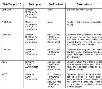
Table 4-2 Initial Al-2024 EBM test observations
INITIAL FESIBILITY TESTS FOR AL 2024
PlateTemp. in ˚C Melt cycle Pre/Postheat Observations
Cold Start 100 reps
10,000mm/s 0.5-3.5mA 0.5mm offset
None Sintering and minor Balling
Cold Start 100 reps
10,000mm/s 0.5-7mA 0.5mm offset
None Cracking of sintered part followed by
balling
Cold start 100 reps
10,000mm/s 0.5-4.0mA 0.5mm offset
pod 100 reps 10,000mm/s 4.0-0.5mA 0.5mm offset
Objective: slowly decrease the heat as it would permit the material to flow after it has been melted to prevent balling. This did not help and balling was still observed
Cold start 100mm/s
3.2mA 0.3mm offset
phd 100 reps 10,000mm/s 0.5-5mA
Objective: Uniformly melt the balled powder. Powder segregated into two layers. Top layer balled and bottom layer sintered
300˚C 100mm/s
3.2mA 0.3mm Offset
phd 100 reps 10,000mm/s 0.5-5mA 0.5mm offset
Objective: study the effect of a hot start. Observed that hot start did not have any significant effect on the quality of the melt
300˚C 100mm/s
1.8mA 0.3mm offset
Phd1 100 reps 10,000mm/s 0.5-5mA phd2 100 reps 10,000mm/s 2-5mA
Objective: higher sintering of powder bed to provide a more stable wettable surface to prevent baling. It was observed that the balling occurred due to sputtering during the melt process.
Samples (25mm sq x approx. 5mm tall) Approx. 100mm
Preheat region
III
I
IV
II
Start plate
Figure 4-2 Configuration for small sample tests of Al 2024
Table 4-3 Small Sample Build Observations for Al-2024
SMALL SAMPLE BUILDS IN AL-2024 Plate
Temp Preheat Sample I Sample II Sample III Sample IV
480˚C 50 reps
10,000 mm/s 0.5-6mA
1.8mA,
100mm/s 2.5mA, 100mm/s 1.8mA, 250mm/s 2.5mA, 250mm/s
Observation: Over melting observed in all samples
550˚C 50 reps
10,000mm/s 0.5-6mA, 0.5mm
9mA, 500mm/s 12.5mA,
500mm/s 9mA, 800mm/s 12.5mA, 800mm/s
Observation: Kinetic energy developed by the melt pool pushes excess melt pool off the build region. This material is very loosely sintered powder and is not damaging to the rake. The higher plate heating temperature also seems to be helping in holding the part more firmly to the plate. High scan rates (sample III & IV) prove to be more effective at reduce balling. Low scanning speeds (sample I & II) also seem to permit the beam to melt deeper into the part. Swelling of the surface was also observed in these samples
Sample III had the cleanest finish; though overmelting seemed to be occurring in all the samples.
550˚C 30 reps
10,000mm/s 0.5-6mA, 1mm
9mA,
1000mm/s 12.5mA, 1000mm/s 9mA, 1300mm/s 12.5mA, 1300mm/s
Observation: The objective of this experiment was to minimize the time spent preheating (also increases powder recovery) and improve the surface finish of the part by speeding up the melting and reducing overmelting. It was observed that the sintering during preheating can further be reduced. The parts obtained during this experiment also showed strong evidence of overmelting.
550˚C 30 reps
10,000mm/s 0.5-5mA, 1.2mm
9mA,
2000mm/s 12.5mA, 2000mm/s 9mA, 3000mm/s 12.5mA, 3000mm/s
Observation: Samples I & II exhibit swelling of the top surface and this is more prominent in sample II. Sample II & IV have a relatively flat top surface but they might have a small amount of porosity as small pinholes were observed in the top surface.
550˚C 30 reps
10,000mm/s 0.5-5mA, 1.2mm
9mA,
2000mm/s 12.5mA, 2000mm/s 9mA, 3000mm/s 12.5mA, 3000mm/s
Since the objective of the study was to develop parameters for freeform fabrication of aluminum parts, a set of experiments was carried out to develop parameters for building overhanging structures. Experiments conducted thus far have not produced a concrete set of parameters for overhanging structures, therefore details of the experiments are not provided. Figure 4-3 clearly shows a more porous surface finish obtained for an overhanging surface.
Top surface of an Al-2024 part made on the Arcam EBM S12 system
Overhanging surface of an Al-2024 part made on the Arcam EBM S12 system
Figure 4-3 Surface roughness of initial Al-2024 specimens
Figure 4-4 ASTM E-8 tensile test specimen dimensions in millimeters
The cross section of the melt region of these tensile specimens was considerably larger than that for the small samples described previously. Two observations were made in this case:
• The parts very frequently cracked during the removal from the steel build plate in the regions showed in the above diagram. The reasons are not entirely clear. It could be due to a combination of the following factors
• The regions become areas where the shear forces are maximum during the part removal
• Residual stress build up due to differences in the thermal expansion of steel and aluminum
• Molten aluminum dissolves steel.
ocean wave, where the pool would build up to an extent where it would spill back onto the melted part causing either waviness or balling on the surface (see Figure 4-5). This problem was solved by sub dividing the scan area into smaller regions that are randomly selected for scanning by the beam. This decreased the size of the weld pool, and the top surface of the part had a fairly reasonable surface finish.
Figure 4-5 Effect of scan length on Al-alloy 2024’s surface finish
Simple rectangular bars were made on the EBM as an alternative to the near net shape ASTM E-8 specimens. Subdivision of the melt area was also incorporated into these builds. Six specimens each were built for each of the four combinations of process parameters.
Large scan areas
Beam Scan Direction
Beam Scan Direction Small scan areas
Solid fused debris
E-Beam
Wave like build up of weld pool
Small weld pool Flaky loose debris
Table 4-4 Processing conditions for Al-2024 test specimens
TENSIL TEST SPECIMENS IN AL-2024 Start Plate
Temp Preheat Sample I-I Sample I-II Sample II-I Sample II-II
550˚C 30reps
10,000mm/s 0.5-6mA
9mA,
3000mm/s 12.5mA, 3000mm/s 9mA, 2000mm/s 12.5mA, 2000mm/s
SAMPLE I-I SAMPLE I-II
Sample I-I side Sample I-I top Sample I-II side Sample I-II top
SAMPLE II-I SAMPLE II-II
Sample II-I side Sample II-I top Sample II-II side Sample II-II top