Available online: https://edupediapublications.org/journals/index.php/IJR/ P a g e | 4711
Improvement of Power System Stability under 3-Phase Faults Using SSSC
P.DHEERAJ KUMAR Assistant Professor
Abstract: -In this examination paper strength of energy frameworks are broke down by utilizing a STATCOM. The STATCOM is a shunt associated certainties gadgets. Generally static compensator upgrades the power framework security under three stage flaws. The transport voltages are controlled utilizing shunt sort realities gadget. The control technique is actualized by static synchronous compensator gadgets and it is discovered that framework execution is improved under three stage issues. Because of three stage blame the issues emerges in generator voltage, generator present, Infinite transport voltage, Infinite transport current and generator stack edge of a power framework are explored in detail and settled by planning and testing a test framework utilizing MATLAB/SIMULINK.
Keywords: STATCOM, FACTS, Transient stability
1.
INTRODUCTION
The power age and transmission is an intricate procedure, requiring the working of numerous parts of the power framework pair to augment the yield. The shunt deficiencies are the most customary sort of shortcomings occurring in the field [1]. Three stage deficiencies caused because of falling pinnacle, disappointment of gear (or) even a line braking and touching the rest of the stages can cause three stage flaws [2]. The Flexible AC transmission framework [FACTS] proposed in 1995. The fundamental reason for FACTS is introducing the power hardware gadgets at the high voltage side of the power matrix to make the total framework electronically controllable. Due to high power semiconductor gadgets and control innovation FACTS gadgets assumes an essential part in control systems.STATCOM is a moment age of the Flexible AC transmission framework gadget. It goes under the classification of completely controlled gadget based compensator. In change of transient soundness utilizing FACTS controller are broke down [3]. Garg et al., detailed about the voltage control and dynamic exhibitions utilizing static compensator [4]. Mathur et al., created thyristor based Flexible AC transmission framework controller for electrical transmission framework [5].An enhanced STATCOM show for control stream examination [6]. In this paper the control technique is executed utilizing static synchronous compensator gadgets. It is discovered that, framework soundness is upgraded with three stage blame. Additionally five parameters are researched in detail by planning and testing a test framework utilizing MATLAB/SIMULINK. Five unique Parameters are spoken to as takes after: 1. Generator Voltage as [Vg] 2. Generator Current as [Ig] 3. Interminable Bus Voltage as [Vb] 4. Vast Bus Current as [Ib] 5. Generator stack point as [ ]
2.
BLOCK DIAGRAM OF TEST SYSTEM
The below test network is tested and parameters such as generator voltage, generator current, bus voltage, bus current and generator load angle performances are examined by connecting STATCOM devices.
Available online: https://edupediapublications.org/journals/index.php/IJR/ P a g e | 4713
3.
DESIGN AND WORKING OPERATION OF STATIC COMPENSATOR
Fig.2 Design of Static compensator
The static compensator primarily consists of a VSC [voltage source converter], shunt connected transformer and DC capacitor [7]. At the same time the voltage source converter is linked to a utility bus through magnetic coupling. Even though it acts like a static part of the rotating synchronous devices, the absence of moving parts makes it to work faster than the older dynamic compensators. The Phase [A] design of STATCOM [static synchronous compensator] is shown in figure.2. The static compensator is a controlled reactive power source. This provides the desired reactive power generation and absorbtion entirely by means of electronic processing of the voltage and current waveforms in a voltage source converter.
Stage1: The amplitude of three phase output voltage varied therefore reactive power exchange can be controlled. Stage 2: The amplitude of output voltage is increased more than bus voltage, so current starts flowing from voltage source converter to AC system through reactance and generates capacitive reactive power.
Stage 3: The amplitude of output voltage is decreased less than bus voltage, so current starts flowing from AC system to voltage source converter through reactance and absorbs inductive reactive power.
Stage 4: The output voltage with AC system voltage is equal, so reactive power exchange becomes zero and static compensator goes to floating state.
3.1 Procedure to Build Up a Test System
Step 1: Design a Test system and create three phase faults near infinite bus as shown in figure 4.
Available online: https://edupediapublications.org/journals/index.php/IJR/ P a g e | 4714 Step 4: Measure the generator voltage, generator current, Bus voltage, Bus current and generator load angle. Step 5: Compare both the result of test system as shown in table.2
4.
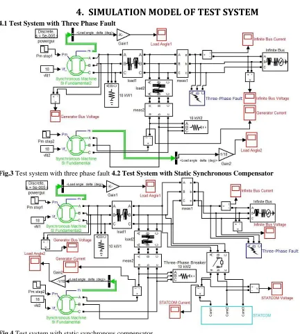
SIMULATION MODEL OF TEST SYSTEM
4.1 Test System with Three Phase Fault
Fig.3 Test system with three phase fault 4.2 Test System with Static Synchronous Compensator
Available online: https://edupediapublications.org/journals/index.php/IJR/ P a g e | 4715
5.
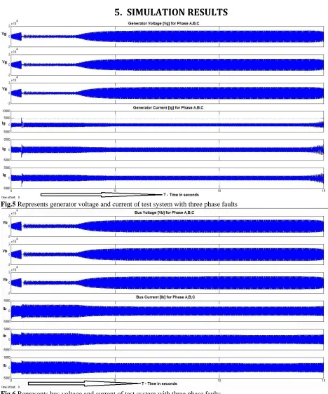
SIMULATION RESULTS
Fig.5 Represents generator voltage and current of test system with three phase faults
Available online: https://edupediapublications.org/journals/index.php/IJR/ P a g e | 4716 Fig.7. Represents generator voltage and current of test system with STATCOM
Available online: https://edupediapublications.org/journals/index.php/IJR/ P a g e | 4717 Fig-.9.Represents Generator load angle of test system with and without STATCOM
Table.2 Test system settling time comparisons
From Figure 5, 6, 7 and 8 we can observe that the generator voltage and current settling time is highly reduced from 4.3 seconds to 1.9 seconds and from 4.3 seconds to 3.3 seconds respectively. Likewise the Bus voltage and current settling time is highly reduced from 5.3 seconds to 0.4 seconds and from 3.3 seconds to 0.4 seconds respectively. So the power system stability is achieved moderately better with static synchronous compensator under three phase fault in the test system.
6.
CONCLUSIONS
In this exploration paper the test framework is planned with three stage flaws utilizing static compensator controller. By utilizing the static synchronous compensator in the test framework the transport voltage are controlled and voltage vacillation is diminished. Generator voltage is balanced out at 1.9 seconds. In like manner the generator current is balanced out at 3.3 seconds. Be that as it may, without FACTS gadget generator voltage and generator current achieves adjustment at 4.3 and 4.3 seconds separately. From the table.2 we gather that the test framework with STATCOM is greatly improved in adjustment of generator stack point, Infinite Bus voltage and current than without FACTS gadget.
REFERENCES
Available online: https://edupediapublications.org/journals/index.php/IJR/ P a g e | 4718 [3]. Chintu Rza Makkar, Lillie Dewan, “Transient stability enhancement using robust FACTS controller-a brief tour, “Canadian Journal on Electrical & Electronics Engineering Volume 1, No.7, December 2010.
[4]. Amit Garg, Sanjay Kumar Agarwal, “Voltage Control and Dynamic Performance of Power Transmission System using STATCOM and its comparision with SVC”, International Journal of Advances in Engineering and Technology, January 2012.
[5]. R.Mohan Mathur, Rajiv K.Varma, “Thyristor Based FACTS Controllers for Electrical Transmission Systems,”IEEE press series on Power Engineering, John Wiley & Sons LTD, 2002.
[6]. Zhiping Yang, Chen Shen, Mariesa L Crow, Lingli, “An Improved STATCOM Model for Power Flow Analysis”, University of Missouri, 2000.