A Compact Four-Element UWB MIMO Antenna
with QSCA Implementation
Jian-Feng Yu, Xiang-Long Liu*, Xiao Wei Shi, and Ze Dong Wang
Abstract—In this paper, a new approach using quasi-self-complementary antenna (QSCA) to reduce the wideband mutual coupling is proposed and discussed. QSCA element proposed in this paper is composed of a semi-circular radiation patch and a complementary-cut ground plane, which is easy to achieve ultra-wideband operation because its impedance is frequency independent. The proposed compact four-element ultra-wideband (UWB) multiple-input multiple-output (MIMO) array consists of four QSCA elements, and by arranging them anticlockwise, a good impedance matching and high port-to-port isolation (|S11| covers 2.95–12.1 GHz with |S21|= |S31| ≤ −15 dB, |S41| ≤ −17.8 dB) can be achieved. Notably, the isolation is obtained without using any other decoupling methods and totally benefits from the asymmetrical radiation property of QSCA. As an example, the proposed four-element UWB MIMO array is fabricated and tested. And the measured radiation pattern, gains and total efficiencies are displayed and show good performances which make it a nice candidate for future UWB diversity applications.
1. INTRODUCTION
Multiple-input multiple-output (MIMO) is a multiplexing technology by adopting multi-antennas both at transmitter and receiver, which can enhance the channel capacity by making full use of the rich scattering environment and without sacrificing additional spectrum or power [1]. For its outstanding performances, MIMO technology will be widely used in the next generation of wireless communication. Ultra-wideband (UWB) is also a technology which can provide massive data transmission at a time by occupying an extremely wide frequency band. For reducing power consumption and interferences with other protocols, its signal transmission is confined in a very low level, which is under−41 dBm/MHz [2]. Since the Federal Communication Commission (FCC) released 3.1–10.6 GHz for unlicensed accessing and commercial use [2], UWB technology has been extensively studied, and many reports have been made. As the demand on wireless communication increases, higher data rate will be a permanent pursuit for future communication network. So to reach a high data rate, even as high as 1 Gb/s, a more advanced technology should be used. As UWB and MIMO technologies can enhance the speed of communication in their own way, a combination of them may be a good solution. And this has been first reported systematically by Kaiser et al. in [3]. As an important component of the UWB MIMO system, UWB MIMO antenna should also be studied, and it is an open issue.
Till now, several reports on MIMO antenna of UWB can be reached, in which different methods have been taken to obtain a good isolation. By placing antenna elements orthogonally, i.e., their radiation orientations and polarizations are orthogonal, the UWB MIMO antenna proposed in [4] obtains a high isolation (|S12| ≤ −20 dB) at 3.1–5.15 GHz. In [5], by placing elements far enough and inserting parasitic stubs, the proposed UWB MIMO array (2.27–10.2 GHz) achieves a very low mutual coupling (|S12| ≤ −20 dB at most of the band). In [6], a tree-like structure was inserted to obtain a good and
Received 8 November 2014, Accepted 26 November 2014, Scheduled 18 December 2014 * Corresponding author: Xiang-Long Liu ([email protected]).
wideband isolation (|S12| ≤ −16 dB). In [7], a pair of long meandering lines is inserted between the two elements to achieve a 15-dB ultra-wideband decoupling. In [8], a pair of bent slits is etched in the ground plane for lower frequency decoupling, and a metal strip is also added between the two elements to reduce the near-field mutual coupling. In [9], the elements are orthogonally arranged, and the ground plane is also etched for isolation improving. For all the mentioned UWB MIMO arrays above, some kinds of decoupling methods are inevitably used to achieve good isolations. This is always a common and effective way to do that, but the decoupling structures, more or less, occupy spaces which may make the antenna larger or more complicated.
In this paper, a new method of reducing mutual coupling between antenna elements in MIMO antenna system is proposed. As an example, a compact four-element UWB MIMO array with high isolation is presented. It simply consists of four quasi-self-complementary antennas (QSCA), which has ultra-wideband operation. And its high isolation is achieved without using any other extra assistant structures or methods. This excellent performance is mainly due to the asymmetrical structures and directional radiation patterns of the quasi-self-complementary antenna (QSCA). The QSCA comes from the concept of self-complementary antenna (SCA) which is a kind of antenna with frequency-independent impedance and large ground plane. Its history, theory and working properties are fully introduced in [10].
2. ANTENNA DESIGN AND ANALYSIS 2.1. QSCA Element Design and Discussion
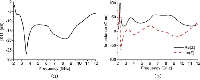
Figure 1 shows the geometry of the proposed QSCA with dimensions of 30×21 mm2 and printed on a 1-mm FR4 substrate. The QSCA is composed of a semi-circular radiation patch, R1 = 6.6 mm, and a complementary cut ground plane,R2 = 9.6 mm. According to the theory of self-complementary antenna (SCA), it has a frequency independent impedance. Although the QSCA proposed here is not the strict SCA, and this is also why we called it QSCA, it also obeys a similar rule and property. It can be seen in Figures 2(a) and (b) that it has wideband operation and constant impedance over frequency. To have a deep understanding of the QSCA, its radiation pattern is also studied, and Figure 3 shows its
21
30
z
x
y
R 2
R1
Figure 1. Geometry of the QSCA element with patch radius, R1 and ground etched slot R2. (Unit: mm).
(a) (b)
normalized simulated 3D radiation patterns at 3.5, 5.5 and 8.5 GHz. The simulation is carried out in high frequency structure simulator (HFSS) in version of 15.0. It can be seen that its radiation patterns keep good stability over a wide band, and the maximum radiation direction mainly aims toy-axis. This mainly comes from its asymmetry structure whose ground plane also as a reflector which makes the QSCA radiate directionally. This may be valuable for MIMO antenna design, in which researchers are eager to seek for any property that can offer any diversity possibility.
2.2. Proposed Compact Four-element UWB MIMO Array Design
By the analysis above, a compact four-element UWB MIMO antenna can be proposed as an example to illustrate its potentiality for UWB diversity application. Figure 4 shows the geometry and dimensions of the proposed four-element UWB MIMO array, which is in a compact size with total dimensions of 40×40 mm2. The proposed array is printed on an FR4 substrate with 1-mm thickness, 4.4 permittivity and 0.02 loss tangent. It is composed of four QSCA elements with their orientations anticlockwise arranged. The QSCA element consists of a semi-circle patch (with optimized radius ofR in = 4.4 mm)
3.5 GHz 5.5 GHz 8.5 GHz
Figure 3. Normalized simulated radiation patterns of the QSCA element at 3.5, 5.5 and 8.5 GHz.
40
14
13 .9
port 3 port 2
port 1 port 4
1
2
40
12.3 z
x y
(a) (b)
Figure 4. Geometry of proposed compact four element UWB MIMO antenna, (a) top view and (b) back view (unit: mm).
(a) (b)
and a complementarily cut ground plane (with optimized radius ofR ex = 8.6 mm). As demonstrated above, due to the asymmetry structure of the QSCA, it owns inherently directional radiation properties which insure that the proposed four-element UWB MIMO array owns low pattern correlation and mutual coupling.
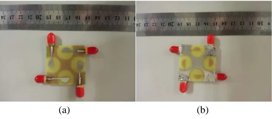
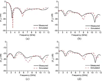
For further analysis of the proposed MIMO array, its model was built and simulated in HFSS v15.0, and its prototype is fabricated and tested. Figures 5(a) and (b) give photos of the proposed four-element UWB MIMO array. Figure 6 shows the simulated and measured S-parameters of the proposed MIMO array. It can be seen that the proposed four-element UWB MIMO array covers 2.95–12.1 GHz with |S12| = |S14| ≤ −15 dB and |S13| ≤ −17.8 dB, which shows a good agreement with the simulated results. Notably, |S12| and |S14| are identical, which may be due to two adjacent elements have the same relative positions, then they show the same mutual coupling properties. For further investigating the mechanism of the proposed four-element UWB MIMO array, its current distributions at 3.5, 5.5 and 8.5 GHz are depicted in Figure 7, with port1 excited and other ports terminated with 50 Ω. It can be seen that the currents are always confined in the area of the element with very little dissipation coupled to other ones.
(a) (b)
(c) (d)
Figure 6. Simulated and measured S-parameters of the proposed four-element UWB MIMO array, (a)|S11|, (b)|S12|, (c)|S13|, and (d)|S14|.
3.5 GHz 5.5 GHz 8.5 GHz
2.3. Key Parameters Optimization
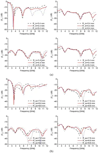
To investigate the stability of the four-element UWB MIMO array design, two key parameters,R in and R ex, of the proposed antenna are analyzed, and their corresponding curves are depicted in Figure 8. It can be seen that the variation of the internal or external radius will not affect the antenna performances seriously, which is good for industrial manufacture. R in mainly impacts the impedance matching while R ex not only affects the impedance matching, but also weights a lot on port-to-port isolation under a low level. So good performance of the proposed four-element UWB MIMO array comes from the compromise of upper and lower band matching.
(a)
(b)
3. RESULTS
Figure 9 shows the radiation patterns of the proposed four-element UWB MIMO array at 3.5, 5.5 and 8.5 GHz in xoy-, xoz- and yoz-plane. For simplicity and geometry symmetry, only radiation patterns of port1 exited is given while others are omitted. It can be seen that Eϕ is directional at xoy-, xoz -and yoz-planes while Eθ shows monopole radiation patterns at yoz- and xoz-planes. Considering the
arrangement and pre-discussions of the array elements, the radiation property of array elements will insure a very low pattern correlation in the far-field. Table 1 illustrates the measured total efficiencies and peak gains of the proposed MIMO array, which shows that the array has good efficiencies in 74∼91% and reaches high peak gains in 3.8∼5.4 dBi. According to [11–13], in an isotropic channel condition, the
xoy-plane
xoy-plane
xoz-plane
xoz-plane
yoz-plane
yoz-plane Eϕ
Eθ
Figure 9. Measured radiation patterns of the proposed four-element UWB MIMO array at 3.5, 5.5 and 8.5 GHz inxoz-,yoz- andxoy-plane.
Table 1. Measured total efficiencies and gains of the proposed four-element UWB MIMO array.
f (GHz) 3.5 4.5 5.5 6.5 7.5 8.5 9.5 10.5
Total eff. 0.91 0.82 0.83 0.79 0.82 0.80 0.76 0.74 Gain (dBi) 3.85 4.13 5.36 4.27 3.04 4.66 5.25 4.67
Table 2. Measured envelope correlation coefficient of the proposed four-element UWB MIMO array.
f (GHz) 3.5 4.5 5.5 6.5 7.5 8.5 9.5 10.5
ρe21 0.004 0.021 0.023 0.030 0.003 0.012 0.005 0.031
ρe31 0.001 0.020 0.010 0.021 0.011 0.001 0.012 0.003
envelope correlation coefficient can be calculated by the equation
ρeij =
|
Aij(Ω)dΩ|
Aii(Ω)dΩ
Ajj(Ω)dΩ
2
(1)
Table 2 gives the measured envelope correlation coefficients (ECC) of the proposed four-element UWB MIMO array, which are calculated by using far-field radiation patterns. It can be read that the far-field ECCs are all below 0.04 which make sure that the pattern correlation between antenna elements is quite low and obtain high diversity performance.
4. CONCLUSION
A compact four-element UWB MIMO array is proposed in this paper. With the good performances and properties of the proposed QSCA monopole, an inherently high isolation is easily achieved without adopting any decoupling methods. The proposed MIMO array can cover the band of 2.95–12.1 GHz with|S12|=|S14| ≤ −15 dB and|S13| ≤ −17.8 dB. The measured ECC is also low enough (below 0.04) to endow the proposed compact four-element UWB MIMO array and obtain good pattern diversity which is paramount for MIMO applications.
REFERENCES
1. Foschini, G. J., “Layered space-time architecture for wireless communication in a fading environment when using multi-element antennas,” Bell Labs Technical Journal, 41–59, 1996. 2. “Federal communications commission revision of Part 15 of the commission’s rules regarding
ultra-wideband transmission system from 3.1 to 10.6 GHz,” ET Docket No. 98-153, Federal Communications Commission, Washington, DC, 2002.
3. Kaiser, T., F. Zheng, and E. Dimitrov, “An overview of ultra-wide-band systems with MIMO,” Proc. of the IEEE, Vol. 97, No. 2, 285–312, 2009.
4. Zhang, S., B. K. Lau, A. Sunesson, and S. L. He, “Closely-packed UWB MIMO/diversity antenna with different patterns and polarizations for USB dongle applications,” IEEE Trans. Antennas Propag., Vol. 60, No. 9, 4372–4380, 2012.
5. Hong, S., K. Chung, J. Lee, S. Jung, S.-S. Lee, and J. Choi, “Design of a diversity antenna with stubs for UWB applications,” Microw. Opt. Technol. Lett., Vol. 50, No. 5, 1352–1356, 2008. 6. Zhang, S., Z.-N. Ying, J. Xiong, and S.-L. He, “Ultrawideband MIMO/diversity antennas with a
tree-like structure to enhance wideband isolation,” IEEE Antennas Wireless Propag. Lett., Vol. 8, 1279–1282, 2009.
7. Lee, J.-M., K.-B. Kim, H.-K. Ryu, and J.-M. Woo, “A compact ultrawideband MIMO antenna with WLAN band-rejected operation for mobile devices,”IEEE Antennas Wireless Propag. Lett., Vol. 11, 990–993, 2012.
8. Li, J.-F., Q.-X. Chu, and T.-G. Huang, “A compact wideband MIMO antenna with two novel bent slits,”IEEE Trans. Antennas Propag., Vol. 60, No. 2, 482–489, 2012.
9. See, T. S. P. and Z. N. Chen, “An ultrawideband diversity antenna,” IEEE Trans. Antennas Propag., Vol. 57, No. 6, 1597–1605, 2009.
10. Mushiake, Y., “Self complementary antenna,” IEEE Antennas and Propagation Magazine, Vol. 34, No. 6, 23–29, 1992.
11. Vaughan, R. G. and J. B. Andersen, “Antenna diversity in mobile communication,” IEEE Trans. Veh. Technol., Vol. 36, No. 4, 149–172, 1987.
12. Ding, Y., Z. W. Du, K. Gong, and Z. H. Feng, “A novel dual-band printed diversity antenna for mobile terminals,”IEEE Trans. Antennas Propag., Vol. 55, No. 7, 2088–2096, 2007.