A Novel Phase Disposition Control for 5-Level
H-Bridge STATCOM with Star Configuration
Ragadeepika Mella1, K.Muni Pratap2
PG Student (PE), Dept. of EEE, AIMS college of Engineering, Andhra Pradesh, India1
Associate Professor, Dept. of EEE, AIMS college of Engineering, Andhra Pradesh, India2
ABSTRACT: This paper presents a transformer less static synchronous compensator (STATCOM) system based on
multilevel H-bridge converter with star configuration. This proposed controlmethods devote themselves not only to the current loop control but also to the dc capacitor voltage control. With regards to the current loop control, a nonlinear controller based on phase disposition theory is used in this cascaded structure STATCOM. As to the dc capacitor voltage control, overall voltage control is realized by adopting a proportional resonant controller. The simulation results are observed using Matlab/Simulink
KEYWORDS: proportional resonant (PR) controller, shifting modulation wave, static synchronous compensator
(STATCOM).
I.INTRODUCTION
Modern power systems are of complex networks, where hundreds of generating stations and thousands of load centers are interconnected through long power transmission and distribution networks. Even though the power generation is fairly reliable, the quality of power is not always so reliable. Power distribution system should provide with an uninterrupted flow of energy at smooth sinusoidal voltage at the contracted magnitude level and frequency to their customers. PS especially distribution systems, have numerous non linear loads, which significantly affect the quality of power. Apart from non linear loads, events like capacitor switching, motor starting and unusual faults could also inflict power quality (PQ) problems. PQ problem is defined as any manifested problem in voltage /current or leading to frequency deviations that result in failure or mal operation of customer equipment. During the past few decades, power industries have proved that the adverse impacts on the PQ can be mitigated or avoided by conventional means, and that techniques using fast controlled force commutated power electronics (PE) are even more effective. PQ compensators can be categorized into two main types. One is shunt connected compensation device that effectively eliminates harmonics.
The STATCOM used in distribution systems is called D-STACOM (Distribution-STACOM) and its configuration is the same, but with small modifications. It can exchange both active and reactive power with the distribution system by varying the amplitude and phase angle of the converter voltage with respect to the line terminal voltage [1].
A multilevel inverter can reduce the device voltage and the output harmonics by increasing the number of output voltage levels. There are several types of multilevel inverters: cascaded H-bridge (CHB), neutral point clamped, flying capacitor [2-5]. In particular, among these topologies, CHB inverters are being widely used because of their modularity and simplicity. Various modulation methods can be applied to CHB inverters. CHB inverters can also increase the number of output voltage levels easily by increasing the number of H-bridges.
STATCOM is a key FACTS controller and it utilizes power electronics to solve many power quality problems commonly faced by distribution systems. Potential applications of STATCOM include power factor correction, voltage regulation, load balancing and harmonic reduction. STATCOM and STATCOM are different in both structure and function, while the choice of control strategy is related to the main-circuit structure and main function of compensators, so STATCOM and STATCOM adopt different control strategy .
strategy is of phase disposition is introduced in this paper. On the basis of DC bus voltage overall control, individual control of each cascade module is proposed.
II. SYSTEM DESCRIPTION
Figure 1 shows single line diagram of a Transmission type Static Synchronous Compensator (T-STATCOM) based on a single Cascaded Multilevel Converter (CMC). It is shown to be connected to Extra High Voltage (EHV) or High Voltage (HV) busbar of the transmission system via a medium voltage (MV) to EHV or HV coupling transformer. Therefore, in Figure 2.1, Xr represents the total leakage reactance of
Figure 1 Single line diagram of a T-STATCOM based on a single CMC
the coupling transformer and if needed the reactance of the series filter reactor. Waveforms of EHV or HV bus voltage,
vs’, line current of T-STATCOM, i, AC voltage of the CMC, vc, voltage of each DC link capacitor, vd1 , and the current
through each DC link capacitor, iC1 are also sketched on Figure 2.1. es’, Xs’ andvs’ are respectively internal source
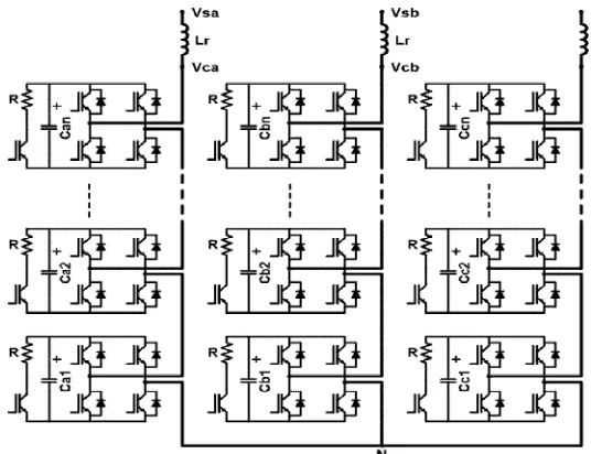
voltage, source reactance and EHV or HV bus voltage all referred to the CMC side. Circuit diagram of star-connected CMC consisting of n number of series connected H-Bridges (HBs) in each phase is as shown in Figure 2. nseriesly connected HBridges give l=2n+1 steps in line-to-neutral voltage waveforms andl=4n+1 steps in line-to-line voltage waveforms, where l is the number of levels from positive peak to negative peak of the waveform under consideration.
III. ACTIVE AND REACTIVE POWER CONTROL
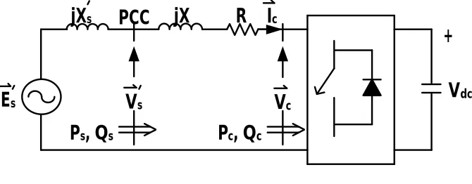
Single-phase Y-equivalent circuit model of the T-STATCOM and its phasor diagram are given in respectively in Figure 3 and Figure 4, where:
Es′: Internal source voltage referred to CMC side
Xs′: Internal source reactance referred to CMC side
PCC: Point of Common Coupling
Vs′: Fundamental voltage component at Point of Common Coupling (PCC) referred to CMC side
X: Total series reactance including leakage reactance of the coupling transformer referred to CMC side and reactance of input filter reactors
Figure 3 Simplified single line diagram of T-STATCOM
V
dcP
C
C
+
R
P
s,
Q
sj
X
E
sV
cj
X
sV
sP
c,
Q
cI
cθ
I
c
δ
R
e
I
m
j
X
I
c
R
I
c
V
c
w
V
s
5
V
dπ/2
0
π 3π/22π
v
cav
'
sa-
5
V
dδ
i
aθ
Figure 4 Phasor diagram for lossy system
IV. INVERTER CONTROL
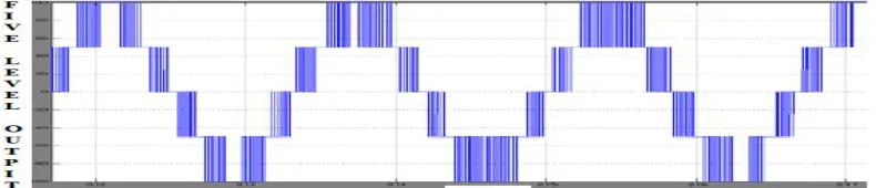
The harmonic components of the output voltage are determined by the carrier frequency and switching functions. Therefore, theirHarmonic reduction is limited to a certain degree. Toovercome this limitation, this paper presents a five-level PWM inverter whose output voltage can berepresented in the following five levels: zero,+1/2Vdc, Vdc, , -1/2V dc , and -V dc . As the number ofoutput levels increases, the harmonic content can bereduced. This inverter topology uses two referencesignals, instead of one reference signal, to generatePWM signals for the switches. Both the referencesignals V ref1and Vref2are identical to each other,except for an offset value equivalent to theamplitude of the carrier signal Vcarrier, as shown inFig.6.
Fig.6 Carrier and reference signals
V.INDIVIDUAL BALANCING CONTROL
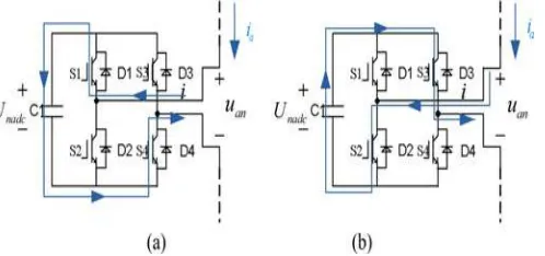
As the overall dc voltage and the clustered dc voltage are controlled and maintained, the individual control becomes necessary because of the different cells have different losses. The aim of the individual balancing control as the third level control is to keep each of 12 dc voltages in the same cluster equalling to the dc mean voltage of the corresponding cluster. It plays an important role in balancing 12 dc mean capacitor voltages in each cluster. Due to the symmetry of structure and parameters among the three phases, a-phase cluster is taken as an example for the individual balancing control analysis. Fig. 7 shows the charging and discharging states of one cell. According to the polarity of output voltage and current of the cell, the state of the dc capacitor can be judged. Then, the dc capacitor voltage will be adjusted based on the actual voltage value.
Fig. 7. Charging and discharging states of one cell. (a) Charging state. (b) Discharging state.
VI. MATLAB MODELLING AND RESULTS
Here Matlab/Simulink model is developed for two cases. In case one D-SATCOM with Linear load and in case two STATCOM with nonlinear load are simulated.
Case A : Linear load
Fig. 8 shows the Matab/Simulink power circuit model of STATCOM. It consists of five blocks named as source block, linear load block, control block, STATCOM block and measurements block.
Figure 9 Source voltage, current and load current with STATCOM.
Case B: Non Linear Load
Figure 11: shows the three phase source voltages, three phase source currents and load currents respectively with STATCOM. It is clear that with STATCOM even though load current is non sinusoidal source currents are sinusoidal.
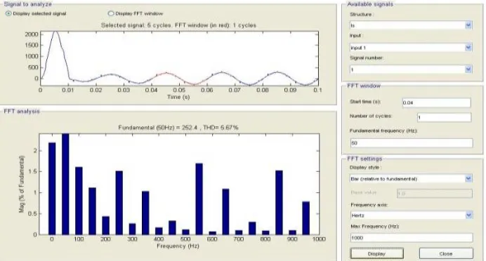
Figure 6.14: shows the harmonic spectrum of Phase-A Source current with STATCOM. The THD of source current with D-STACOM is 5.05%
VI.CONCLUSION
In this paper a five level inverter used in a STATCOM in Power System and it was successfully demonstrated in MatLab/Simulink. The benefits of five level inverter are low harmonic distortion, reducing number of switches and reducing switching losses. A STATCOM with five levels Cascaded H-Bridge inverter was investigated. Mathematical model for single H-Bridge inverter was developed which can be extended to multi H-Bridge. The source voltage, load voltage, source current, load current, power factor simulation results under non-linear loads were presented. Finally Matlab/Simulink based model was developed and a simulation result was presented for both linear and non-linear loads.
REFERENCES
[1] XuefengLiang,YonghaiXu, Xiaolu Chen “The Simulation Research of STATCOM Based on Cascaded Multilevel Converter” IEEE Trans. pp.494-498 Feb. 2011.
[2] J.S.Lai, and F.Z.Peng “Multilevel converters – A new breed of converters,”IEEE Trans. Ind.Appli., vol.32, no.3, pp.509-517. May/ Jun. 1996. [3] Wenchao Song and Alex Q. Huang, “Fault-Tolerant Design and Control Strategy For Cascaded H-Bridge Multilevel Converter-Based STATCOM,” IEEE Trans. Ind.Electron., vol.57, pp.2700-2708.Aug.2010.
[5] SirirojSirisukprasert, Alex Q. Huang, and Jih-Sheng Lai “Modeling, Analysis and Control of Cascaded-Multilevel Converter-Based STATCOM,” IEEE Trans. Ind. Electron., vol.49, no4, pp.2561-2568. Aug.2003.
[6] J. J. Parseba, G. F. Reed, M. Takeda, and T. Aritsuka, “FACTS and custom power equipment for the enhancement of power transmission system performance and power quality,” presented at the Sump. Specialists Electric Operational and Expansion Planning Conf. (SEPOPE), Curitiba, Brazil, 2000.
[7] K.Ramesh Kumar, D.Kalyankumar. And V.Kirbukaran “An Hybrid Multi Level Inverter Based DSTATCOM Control,” presented at the Majlesi Journal of Electrical Engineering, Vol. 5, No. 2, pp17-22, June 2011.
[8] N.Srinivasa Rao and G.V.Siva Krishna Rao “Modeling& Simulation of DSTATCOM for Power Quality Improvement,” IJERD,ISSN: 2278-067x, Volume 1, Issue 12 (July 2012), Pp.33-40
[9] J. A. Barrena, S. Aurtenetxea, J. M. Canales, M. Á. Rodríguez, and L. Marroyo, “Design, analysis and comparison of multilevel topologies for DSTATCOM applications,” presented at the European Conf. Power Electronics and Applications (EPE), Dresden, Germany, 2005.