ISSN: 1992-8645 www.jatit.org E-ISSN: 1817-3195
336
SURFACING POINT CLOUD DATA FROM MULTIPLE
ACQUISITIONS
1*
GOPAL GAIKWAD, 2SHRUTI PATIL, 3ROHIT PATIL, 4NITIN KARMARKAR
1,2
Symbiosis Institute Of technology (SIT), Symbiosis International University (SIU), Lavale Pune 412115, Maharashtra State, India
3,4
Renishaw India, Raisoni Industrial Estate, Maan Mulshi Pune 411057, Maharashta State, India E-mail: [email protected], [email protected],[email protected],
4
ABSTRACT
The trend of using LIDAR (Light Detection and Ranging) based systems for surveying is increasing every day. These systems output ‘Point cloud data’, which can be further processed to produce vital information about the topology of the surveyed area. In this paper, we provide a novel method to process the point cloud data and build the model of the surveyed area that represent the surveyed area more accurately. This method is more noise tolerable and no need to care about the outliers as these outliers gets eroded by morphological erosion operation. In this way, we will not lose features. The scope of this work is restricted to processing the data surveyed from a closed cavities or cave to understand their topology and estimate their volume. Generally, the surveyed data collected using multiple sample sets and as such, each sample set does not register with each other’s and may consist holes in point cloud due to operational discrepancies. This approach will use the morphological operation to fill the holes. We thereafter use the Sobel cross gradient operator to find out a common border. The KNN algorithm will then define smoother and much thinner.
Keywords: Point Cloud, Morphological Operation, Sobel Mask Filter, KNN Algorithm, Multiple
Registration, And Gradient Function.
1. INTRODUCTION
It is recommended that underground mining area should filled for the safety purposes. To conclude either the mining should continue or not the awareness of mined volume is necessary. To determine the operational efficiency at the end of the day we can use the information to get an idea about how much material is extracted from the mines. This system will be useful in state of affair in speed, accuracy and safety should be considered. LiDAR is remote sensing technology that illuminates the eye safe lasers in 360 degree and observes the reflection of those illuminated lasers by that exact position of object can be calculated with the expression(1). To collect the data of whole cave the LiDAR device will be mounted over some carrier and roll through the cavity for multiple times to cover the data collection with sufficient amount of data. Data collected in such a way may be contaminated with holes and overlapping regions due to multiple registration. Volume calculation of such unstructured bodies is complicated. Main objective of this study is to provide the novel method to construct the 3D model from the noisy and sparse point cloud without any feature loss. This method concerns
about the accuracy of the topological structure with preserving minuet level features as much as possible so that constructed model fulfill the requirement of engineering application.
… 1 Figure (1) Represent the data acquired in multiple scan colours are used to represent data acquired in different scan
Fig. 1 Data Collected In Multiple Datasets (Each
Dataset Represented By Different Colour).
2. LITERATURE REVIEW
ISSN: 1992-8645 www.jatit.org E-ISSN: 1817-3195
337 operational discrepancy. Here most existing surface reconstruction methods fails to behave as expected because they rely on the neighbor relationship, which might get affected by inaccuracy in the data collection. This method keep in mind that features of point cloud data should not be disturbed throughout the process. Other approach based on the topological structures, in which topological structure definition of the object is available as input. ‘Fast and accurate Multiview reconstruction by multi stage prioritized matching surface reconstruction’ approaches based on the model construction of the object from high definition images [2]. In which multiple calibrated images captured from different viewpoints. From those images depth map is generated to construct the multi-view model of object, but unable to work in cloudy environment and dark.
Moving least squares Reconstruction Expects each sample set is associated with oriented normal and estimate of local spacing. MLS assumes the data is cleaned, registered and transformed to world coordinate system, and do not consider about the multiple registration. Multiple registration will have multiple orientation details [1]. MLS uses isosurface extraction algorithm to produce mesh this will lead to jagged mesh that will not useful. ‘Orientation interface framework for surface reconstruction from unrecognized point cloud’ ling
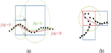
etal. (2011) uses an octree to subdivide a data for the processing seems to be promising as at any given point of time we will be dealing with huge amount of point cloud data [5]. In addition, approach talks about the orientation correction to produce continues surface, but the multiple registration leads to the incorrect shape. Because the approach is based on the local surface fitting function, due to multiple registration and data is not uniform. The local shape function lead ambiguously as in Fig.2 (b).
Fig. 2 (A) Local Shape Function Fi And Fj Are Supposed To Be Signed At The Common Corners Of The Octree
Cells, (B) Local Shape Function Leading to Ambiguity due to Multiple Registration [5]
Poisson surface reconstruction method will eliminate holes in the samples and even can tolerate noise. Nevertheless, need specific data for processing oriented points are the input. This method considers data at once instead of going locally to fitting surface. Poisson method is PDE based Reconstruction this method do not merge the overlapping region introduced due to the multiple registration.
[image:2.612.103.291.579.670.2]ISSN: 1992-8645 www.jatit.org E-ISSN: 1817-3195
338
3. PROPOSED APPROACH
Point cloud data is acquired from multiple scans in the caves, and that cave point cloud data is merged to make super set of data. Data may contain
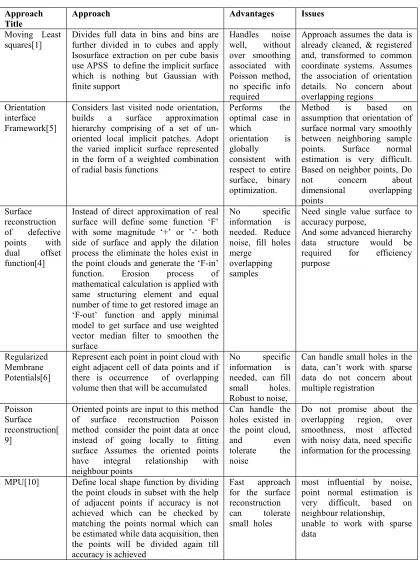
[image:3.612.85.505.103.671.2]holes and at some places may have overlapping region because of the miss registrations. To avoid the holes in scanned data and make the point data as watertight body, we will use the dilation Table 1 Comparative Analysis of Different Methods
Approach Title
Approach Advantages Issues
Moving Least squares[1]
Divides full data in bins and bins are further divided in to cubes and apply Isosurface extraction on per cube basis use APSS to define the implicit surface which is nothing but Gaussian with finite support
Handles noise well, without over smoothing associated with Poisson method, no specific info required
Approach assumes the data is already cleaned, & registered and, transformed to common coordinate systems. Assumes the association of orientation details. No concern about overlapping regions
Orientation interface Framework[5]
Considers last visited node orientation, builds a surface approximation hierarchy comprising of a set of un-oriented local implicit patches. Adopt the varied implicit surface represented in the form of a weighted combination of radial basis functions
Performs the optimal case in which
orientation is globally consistent with respect to entire surface, binary optimization.
Method is based on assumption that orientation of surface normal vary smoothly between neighboring sample points. Surface normal estimation is very difficult. Based on neighbor points, Do not concern about dimensional overlapping points
Surface reconstruction of defective points with dual offset function[4]
Instead of direct approximation of real surface will define some function ‘F’ with some magnitude ‘+’ or ’-‘ both side of surface and apply the dilation process the eliminate the holes exist in the point clouds and generate the ‘F-in’ function. Erosion process of mathematical calculation is applied with same structuring element and equal number of time to get restored image an ‘F-out’ function and apply minimal model to get surface and use weighted vector median filter to smoothen the surface
No specific information is needed. Reduce noise, fill holes merge
overlapping samples
Need single value surface to accuracy purpose,
And some advanced hierarchy data structure would be required for efficiency purpose
Regularized Membrane Potentials[6]
Represent each point in point cloud with eight adjacent cell of data points and if there is occurrence of overlapping volume then that will be accumulated
No specific information is needed, can fill small holes. Robust to noise,
Can handle small holes in the data, can’t work with sparse data do not concern about multiple registration
Poisson Surface reconstruction[ 9]
Oriented points are input to this method of surface reconstruction Poisson method consider the point data at once instead of going locally to fitting surface Assumes the oriented points have integral relationship with neighbour points
Can handle the holes existed in the point cloud, and even tolerate the noise
Do not promise about the overlapping region, over smoothness, most affected with noisy data, need specific information for the processing
MPU[10] Define local shape function by dividing the point clouds in subset with the help of adjacent points if accuracy is not achieved which can be checked by matching the points normal which can be estimated while data acquisition, then the points will be divided again till accuracy is achieved
Fast approach for the surface reconstruction can tolerate small holes
ISSN: 1992-8645 www.jatit.org E-ISSN: 1817-3195
339 morphological set method to fill in the gaps. The dilation process will not dilute the topological structure of the point cloud object, iteratively we will apply the dilation until we get watertight object body. Then we will fill the object body by simple flood filling algorithm, and we will apply equal number of erosion operation to restore the object body (outside function). To derive the inside function will apply the same number of dilation on flooded area how many applied to make point data watertight. Then apply the Gaussian separately on both the function to introduce the change along the boundary of the functions. By applying Sobel mask filter, on the functions will get the functions body with preserving the water-tightness, because Sobel mask filter will capture the relative change in intensity between two successive points. After applying the Sobel mask filter, we will get the gradient images. We will apply the K-NN regression algorithm on normalized union of both the functions. And then the thresholding the values based on the k so the outline border will be skeletonize with preserving water-tightness and object shape, process will be continued until object body preserve the water-tightness.
3.1 Construct outline functions
Objective of this step is to construct the watertight object offset gradient functions. We will transform the point cloud data into the world coordinate system, so that it will be easy for the processing in the 3D space. Due to operational discrepancies, point cloud contains some holes and noise as shown in fig. (4). Point cloud data is acquired in multiple scan with different orientation so they may not register with each other. To eliminate the holes and ensure the water-tightness of surface body of object, apply the dilation set morphological operation [4]. In binary image, dilation will enlarge the object body and will scale down the holes. Apply the dilation iteratively until the surface body does not ensure the water-tightness. To check either surface is watertight or not, flood fill algorithm [4] is used.
⊕ ,",# $% ,",# & ',(,) ∙
+',"+(,#+)]
...2 [12]
Here B is structuring element, which should be selected based on the error distribution in the sample set. If structuring element is too small with respective to error distribution then several number of dilation are needed which lead to
inefficient and time consuming approach[4]. After each dilation flood-fill the object body from any arbitrary inside point. If the flood fill reaches any edge of the bounding box, then stop and apply the dilation. Continue the process until the object body became the watertight body. Selecting the inside point for flood fill is challenging and should be selected intelligently.
When object body represent the water-tightness, flood fill the body and then apply the erosion morphological operation. Number of erosion operations should be same as number of dilation operations with the same structuring element. So this process will restore the body object as original it was, with elimination of holes inside the ‘point cloud data’. Equation number 3 for erosion [12] resulting function is outside function. Inside function is calculated by applying number of dilation on ‘inside’ area of last dilation operation performed to get watertight body as shown in equation number(4) [4]. The number of dilations should be same as number of previously applied dilation operations. Apply Gaussian on both Inside and Outside functions and then capture the change using Sobel mask operator to get two thick boundaries. The width of the inside and outside function is based on the convolution matrix used to apply Gaussian in the 3D space. Convolution matrix used in Gaussian should be selected such that the change captured by Sobel Mask operator is as minimum as possible. In our approach convolution matrix is of size 3 3 3 and the convolution matrix values calculated with the following expression (5) [4].
⊕ ,",#
-. ,",#&$% /',"/(,#/) , ',(,)
] … 3
01( 023 4 ⊕ ⊕B …4
5 6, 7, 8 9
:;<
+=<>?<>@<
ISSN: 1992-8645 www.jatit.org E-ISSN: 1817-3195
[image:5.612.84.318.67.435.2]340 Fig. 4 Typical Scan from a Mine Shaft Constructed from
‘6’ Data Collections
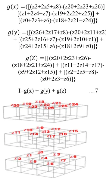
How to apply the Sobel mask filter to capture the change introduced at the edge of object body: To capture change in each direction we use three different 3D operators corresponding to each direction as size of 3 3 3. Sobel mask filter is nothing but the second order partial derivative as shown in expression (6). In Sobel mask filter operator, values should be set such that addition of all the values is zero. Values in Sobel mask filter operator are set same as used for 2D image [13] with addition of depth of z-axis so that it will capture the change along all the three direction collectively.
B<2
B < 0 6 C 1 C 0 6 3 1 3 20 6
… 6
Gradient image (function) is computed with the Sobel mask filter operator which is a linear operator. Apply Sobel mask filter operator on image to capture the relative change in the intensity introduced by the Gaussian. G(x), G(y), and G(Z) will grab the relative change of intensity in X,Y, and Z direction respectively of 3D image. By combining relative change in the intensity we will get the gradient image (I) which represent the watertight object body.
F 6 {[(z2+2z5+z8)-(z20+2z23+z26)] + [(z1+2z4+z7)-(z19+2z22+z25)] +
[(z0+2z3+z6)-(z18+2z21+z24)]}
F 7 {[(z26+2z17+z8)-(z20+2z11+z2)] + [(z25+2z16+z7)-(z19+2z10+z1)] +
[(z24+2z15+z6)-(z18+2z9+z0)]}
F G {[(z20+2z23+z26)-(z18+2z21+z24)] +
[(z11+2z14+z17)-(z9+2z12+z15)] + [(z2+2z5+z8)-(z0+2z3+z6)]}
I=g(x) + g(y) + g(z) …7
Fig 5 Sobel mask in 3D Euclidian space with depth of Z direction.
3.2 Compute the Narrow Band Surface
[image:5.612.75.517.69.505.2] [image:5.612.339.515.212.507.2]ISSN: 1992-8645 www.jatit.org E-ISSN: 1817-3195
341 cloud with optimized error in resulting surface. To construct zero level set surface from the gradient function, we will take union of both the gradient functions and normalize combined functions with same intensity values across the image. Then apply the KNN regression algorithm on the image so the algorithm will set the possible highest values near to center position of the gradient function outline, and possible lowest value near to the edge. So by thresholding we make the thinner surface as shown in the figure (6c) where blue colour outline gets eliminated by thresholding. The process will continue until the given surface remains watertight. Finally, the resulting surface will be very much close to point cloud and thus can be used to represent a complete body of that point cloud data.
Fig. 6 (a) Section view of outline function(gradient function image),(b) Output of KNN algorithm Representing Distinct Intensity Values with Different
Colour, (c) Output of Threshold Low Intensity Values get Eroded as Blue and Gray Colour are Erased in c and
Outline Function get Thinner
4. ANALYSIS
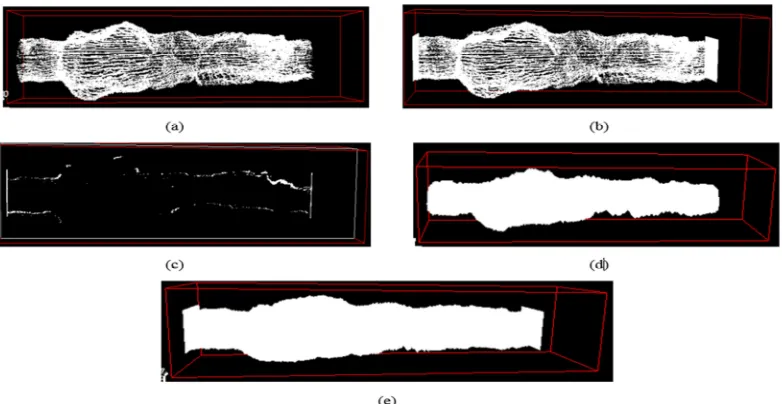
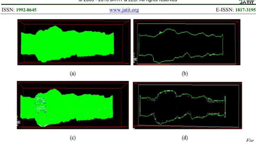
Fig. 7(a) represents the point cloud data that is distributed with irregular intervals. This data is surveyed from mine in multiple Acquisitions with different orientations. Data contaminated with holes and density of the points is not uniform. Point data contain hallow body with some volume ‘V’. Test data consists enough holes among the points, which will be filled with the dilation process. We will apply some conventional cap at the both ends to represent the closed cavity as shown in fig 7(b). We took the structuring element of size 5 5 5
in 3D space. Fig 7(c,d) visualize the inside and outside functions respectively. Watertight body is computed with the morphological operators. On this watertight-filled functions, apply the convolution filter with the kernel size of 3 3 3
[image:6.612.85.294.291.368.2]which help to introduce the enough change along the edge of the body, which will be captured by Sobel mask filter of 3 3 3 size. Fig 7(d) represent the section view of the gradient function.
Fig. 7 (a) Input Point Cloud with the Holes and Overlapping Regions, (b) Point Cloud With Capping Both Side to Make the
[image:6.612.101.492.410.612.2]ISSN: 1992-8645 www.jatit.org E-ISSN: 1817-3195
342
Fig 8(a) Reconstructed Surface From Point Cloud, (b)Section View of Reconstructed Surface, (c) Union of Both
Reconstructed Surface and Point Cloud Data , (d) Section View of Reconstructed Surface and Point Data
Fig 8 Represent the reconstructed surface from the point cloud. In analysis, image blending is used to represent the reconstructed surface and the original point cloud. Colours differentiates between the reconstructed surface and original point cloud body. Green colour is used to represent the reconstructed surface and blue represents intersection of both the original point cloud and the reconstructed surface. White colour represent the area where the point cloud lie outside the reconstructed surface.
Reconstructed surface fill the holes flatly with the help of dual gradient functions. Even though the data contains overlapping points and holes, the reconstructed surface will match with the point cloud data. This method preserves the features and shape of the point data in reconstructed surface irrespective of error in the point cloud. In given analysis, the results are visualized with details of accuracy. Where there are holes of considerable sizes, the surface is reconstructed by filling the holes flatly, preserving the body definition. This method do not loose the feature.
In above figure 8(a) we found the closed water tight body which consumes some volume.
We can Compute that volume as
Volume=number_of_Grids_inside_the_body × size_of_eachgrid. Grid size can be computed as step size in X,Y,Z direction as bellow expression(8). We will flood fill the body with distint value and can compute how many voxels inside the body.
Step M NOP
Q RS+Q T
TU V W T Q W X T
Step M NOY
Z RS+Z T
TU V W T Z W X T
Step M
NO[
\ RS+\ T
TU V W T \ W X T …8
size_of_eachgrid Step M
NOP Step M NOY
Step M NO[
Final_volume number_of_grid_inside
size_of_each_grid
Table 2 Steps And Stepsize Details
Axis Max Min Steps Stepsize/in
terval
X-axis 67664
4
676635.50 099945
140 0.0607071
467858207
Y-axis 90007
9
900071.05 999756
140 0.0567143
031429233
Z-axis 4882 4848.2231
4453
450 0.0750596
788222214
Grid size= 0.00025842773643964146 units
Number of voxels lies inside the body=3024405
Volume of object body 3024405
0.00025842773643964146
[image:7.612.88.522.65.306.2]ISSN: 1992-8645 www.jatit.org E-ISSN: 1817-3195
343
5. CONCLUSION AND FUTURE WORK
In this approach, we are capable of handling the data collected in multiple Acquisitions. Data can be contaminated with noise, holes and some overlapping regions. Therefore, to avoid these possibilities morphological operations help to fill the holes and restore the original body object. With the help of Gaussian and gradient function, we can define the watertight object body. This method does not loose features of the original body. This method will provide possible minimal inside neighbor set. With the help of inside neighbor set information, we can define the volume of the object body. Because grid size of the image is distributed uniformly throughout the image, we can define the volume of the body.
Future work for this research will be improving water tightness test to achieve improved efficiency. In addition, handling of large point cloud data will be improved by using advanced data structures like octree to improve performance.
6. ACKNOWLEDGEMENT
We express our deepest gratitude to Renishaw Metrology Systems LTD, Pune, India For allowing and facilitating our work. Our special thanks to Director of Software Division, Renishaw Metrology Systems Ltd, Pune, Mr. Vikas Saxena.
REFRENCES:
[1] Bruce Merry, And James Gain, “Moving Least-Squares Reconstruction of Large Models with GPU ”,IEEE trans, visualization and computer graphics, Vol. 20 ,no.2,feb 2014 [2] Markus Ylimaiki, juho kannala, Jukka
Holappa,Sami S.Brandt, & Janne Heikkila, “Fast And accurate multiview Reconstruction by Multi stage prioritised matching”,IET computer vision ISSN 1751-9632,2014 [3] Murat Arikan,Reinhold Preiner, Claus
Scheiblauer,Stefan Jeschke, & Michael Wimmer, “Large_scale Point_cloud ViSualization through localized textured
surface Reconstruction”, IEEE
Trans,Vol.20,No.9, sept 2014
[4] Kun Mo and Zhoupin Yin (2011). “Surface Reconstruction of Defective Point Clouds Based on Dual Off-Set Gradient Functions”, Advances in Mechatronics, Prof. Horacio Martinez-Alfaro (Ed.), ISBN: 978-953-307-373-6, InTech, DOI: 10.5772/21087. Available from:
http://www.intechopen.com/books/advances- in-mechatronics/surface-reconstruction-of- defective-point-clouds-based-on-dual-off-set-gradient-functions
[5] Yi-Ling Chen “Orientation Interface Framework for surface reconstruction From Unrecognised point clouds”, IEEE Trans, Image Processing, Vol.20,no.3,March 2011 [6] Andrei C. Jalba, and Jos B. T. M., “ Efficient
surface Reconstruction From noisy data using regularised membrane potentials”, IEEE Trans, Vol.18, no5, may 2009
[7] P. Alliez, D. Cohen-Steiner, Y. Tong, M. Desbrun, “Vornoi-based Variational Reconstruction of unoriented point sets”, Eurographics Symposium On Geometry Processing,2007
[8] Marek Vanco, Bernd Hamann,Guido Brunnett, “Surface Reconstruction From Unorganised Points Data With Quadrics”, Computer graphics Forum, 2007
[9] Michael Kazhdan, Matthew Bolitho, & Hugues
Hoppe, “Poisson Surface
Reconstruction”,Eurographics Symposium on Geometry Processing,2006
[10] Yutaka Ohtake, alexandar Belyaev, Mark Alexa, Greg Turk, Hans-peter seidel, “Multi_level Partition of unity Implicit”,2001 [11] J. c. Carr, R. K. Beatson, J. B. Cherrie, T.J.
Mitchell, W.R. Fright, B.C. McCullum, T.R. Evans, “Reconstruction And Representation of 3D Objects with Radial Basis Function”,2001. [12] Frank Y. shih, “image processing and
Mathematical Morphology Fundamentals and applications” ,Crc press taylor and francis group,ISBN-13:978-1-4200-8944-8,2009 [13] Rafael C. Gonzalez and Richard E. Woods,