eRA Y
X-MP
EA
Computer
Systems
Functional Description Manual
HR·3020
Copyright e 1988 by Cray Research, Inc. This manual or parts thereof may not be reproduced in any form unless permitted by contract or by written permission of Cray Research, Inc.
The CRAY X-MP EA computer system is exempt from the technical requirements of the FCC's Part 15 Subpart J rules pursuant to Section 15.801 (C).
The UNICOS operating system is derived from the AT&T UNIX System V operating system. UNICOS is also based in part on the Forth Berkely Software Distribution under license from The Regents of the University of California.
CRAY, CRAY-1, SSD, and UNICOS are registered trademarks and CFT, CFT77, CFT2, COS, CRAY-2, CRA Y X-MP, CRA Y X-MP Extended Architecture, CRA Y Y-MP, CSIM, HSX, lOS, SEGLDR, and SUPERLINK are trademarks of Cray Research, Inc.
Amdahl is a registered trademark of Amdahl Corporation. AOS is a registered trademark of Data General Corporation.
Apollo and DOMAIN are registered trademarks of Apollo Computer Inc. CDC is a registered trademark of Control Data Corporation.
ECLIPSE is a registered trademark of Data General Corporation. Ethernet is a registered trademark of the Xerox Corporation.
HYPERbus and HYPERchannel are registered trademarks of Network Systems Corporation. IBM is a registered trademark of International Business Machines Corporation.
UNISYS is a registered trademark of UNISYS Corporation. UNIX is a registered trademark of AT&T.
AEGIS is a trademark of Apollo Computer Inc. CYBER is a trademark of Control Data Corporation.
DEC, PDP, VAX, VAXcluster, and VMS are trademarks of Digital Equipment Corporation. Honeywell is a trademark of Honeywell, Incorporated.
LANlord is a trademark of Computer Network Technology Corporation. Sun-3 is a trademark of Sun Microsystems, Inc.
The TCP/IP documentation is copyrighted by The Wollongong Group and may not be reproduced, transmitted, transcribed, stored in a retrieval system, or translated into any language or computer language, in any form or by any means, electronic, mechanical, magnetic, optical, chemical, manual or otherwise, except as provided in the license agreement governing the documentation or by written permission of The Wollongong Group, Inc., 1129 San Antonio Road, Palo Alto, California 94303. The Wollongong software and documentation is based in part on the Fourth Berkeley Software Distribution under license from The Regents of the University of California. e The Wollongong Group 1985.
MVS, VM, and VM/CMS are products of International Business Machines Corporation. NOS, NOS/BE,and NOS/VE are products of Control Data Corporation.
Requests for copies ofCray Research, Inc. publications should be directed to:
CRA Y RESEARCH, INC. Distribution Center 2360 Pilot Knob Road Mendota Heights, MN 55120
Comments about this publication should be directed to:
Record of Revision
Each time this manual is revised and reprinted, all changes issued against the previous version are incorporated into the new version and the new version is assigned an alphabetic level which is indicated in the publication number on each page of the manual.
Changes to part of a page are indicated by a change bar in the margin directly opposite the change. A change bar in the footer indicates that most, if not all, of the page is new. If the manual is rewritten, the revision level changes but the manual does not contain change bars.
REVISION DESCRIPTION
PREFACE
This manual describes the basic functions of the CRAY X-MP Extended Architecture (EA) computer system manufactured by Cray Research, Inc. (CRI).
AUDIENCE
This manual is written primarily for customers. It describes the design and architecture of the CRA Y X-MP EA computer system and its associated peripheral devices.
ORGANIZATION
This manual is organized into the following tabbed sections. A detailed table of contents is included at the beginning of each tabbed section.
SECTION 1 - CRA Y X-MP EA COMPUTER SYSTEM OVERVIEW - This section introduces and describes the CRA Y X-MP EA system components and support equipment.
SECTION 2 - CRA Y X-MP EA MAINFRAME - This section describes the basic architecture of the CRAY X-MP EA mainframe and is divided into two subsections. The first subsection describes the hardware architecture of the mainframe. The second subsection describes the CPU instructions. Specification sheets for the CRA Y X-MP EA computer system are included at the end of this section.
SECTION 3 - 1/0 SUBSYSTEM - This section describes the basic architecture and functions of the 1/0 Subsystem (lOS). A specification sheet for the lOS is included at the end of this section.
SECTION 4 - SSD SOLID-STATE STORAGE DEVICE - This section describes the basic architecture and functions of the SSD solid-state storage device. A specification sheet for the SSD is included at the end of this section.
SECTION 5 - PERIPHERAL EQUIPMENT - This section describes the function of the disk drives and network interface equipment used by the CRA Y X-MP EA computer system. Specification sheets for the the different disk drives and network interfaces are included at the end of this section.
SECTION 6 - SOFTWARE OVERVIEW - This section provides an overview of the software available for the CRA Y X-MP EA computer system.
NOTATIONAL CONVENTIONS
The following conventions are used throughout this manual. Convention
Lowercase italic Xorxorx n
(value)
Register bit designators
Number base
Description
Variable information. An unused variable. A specified value.
The contents of the register or memory location designated by value.
Register bits are numbered from right to left as powers of 2. Bit 20 corresponds to the least significant bit of the register, With the exception of the Vector Mask register. The Vector Mask register bits correspond to a word element in a vector register; bit 263 corresponds to element 0 and bit 20 corresponds to element 63.
All numbers used in this manual are decimal, unless otherwise indicated. Octal numbers are indicated with an 8 subscript. Exceptions are register numbers, the instruction parcel in instruction buffers, and instruction forms, which are given in octal without the subscript.
The following are examples of the preceding conventions.
Example Description
Transmit (Ak) to Si Transmit the contents of the A register specified by the k field to the S register specified by the i field.
167ixk Machine instruction 167. Thej field is not used.
Read n words from Read a specified number of words from memory. memory
Bit 263
10008
The value represents the most significant bit of an S register or element of a V register.
RELATED PUBLICATIONS
For additional information on site planning refer to the following publications:
• HR-0080
• HR-0082
• HR-3017
• HR-3018
• HR-3019
Cray Peripheral Equipment Site Planning Reference Manual. This
manual provides site planning information for operator and maintenance workstation equipment, Disk Storage Units (DSU s), and Front-end Interface (FEI) cabinets.
Cray Support Equipment Site Planning Reference Manual. This
manual provides site planning information for refrigeration condensing units (RCUs) and motor-generator sets (MGS).
CRAY X-MP EA 6-column Computer Systems Site Planning Reference Manual. This manual provides site planning information for the CRA Y X-MP EA 6-column mainframe, the 1/0 Subsystem (lOS), and the SSD solid-state storage device.
CRAY X-MP EA 8-column Computer Systems Site Planning Reference Manual. This manual provides site planning
information for the CRA Y X-MP EA 8-column mainframe, the 110 Subsystem (lOS), and the SSD solid-state storage device.
CRAY X-MP EA 12-column Computer Systems Site Planning Reference Manual. This manual provides site planning
CONTENTS
1 - CRAY X-MP EA COMPUTER SYSTEM OVERVIEW ... 1-1
CRA Y X-MP EA MAINFRAME ... 1-2
I/O SUBSYSTEM ... 1-3
SSD SOLID-STATE STORAGE DEVICE ... . . .. 1-4
DISK STORAGE UNITS ... 1-5 COMMUNICATION INTERFACES ... 1-5 OPERATOR AND MAINTENANCE WORKSTATIONS ... 1-6 POWER AND COOLING SUPPORT EQUIPMENT ... 1-6
2 - CRA Y X-MP EA MAINFRAME ... 2-1
CPU SHARED RESOURCES ... 2-1
CPU COMPUTATION SECTION ... 2-3 CPU CONTROL SECTION ... 2-21
SPECIAL FEATURES OF THE CRA Y X-MP EA COMPUTER SYSTEM ... 2-28 CPU INSTRUCTIONS ... 2-39 INSTRUCTION FORMATS ... 2-39 INSTRUCTION DIFFERENCES BETWEEN THE X-MODE AND Y-MODE ... 2-43 SPECIAL REGISTER VALUES ... 2-45 MONITOR MODE INSTRUCTIONS ... 2-45 SPECIAL CAL SYNTAX FORMS ... 2-45 CPU INSTRUCTION SUMMARY ... 2-46 CRA Y X-MP EAllse COMPUTER SYSTEM SPECIFICATION SHEETS ... 2-69 CRAY X-MP EAlI COMPUTER SYSTEM SPECIFICATION SHEETS ... 2-73 CRA Y X-MP EAl2 COMPUTER SYSTEM SPECIFICATION SHEETS
CRA Y X-MP EAl4 COMPUTER SYSTEM SPECIFICATION SHEETS
2-77
2-81
3 - I/O SUBSYSTEM ... 3-1
I/O PROCESSORS ... 3-1
I/O SUBSYSTEM BUFFER MEMORY ... 3-4
OP~RATOR WORKSTATION ... 3-4 I/O SUBSYSTEM MODEL C SPECIFICATION SHEET ... 3-5 I/O SUBSYSTEM MODEL D SPECIFICATION SHEET ... 3-7
4 - SSD SOLID-STATE STORAGE DEVICE ... 4-1
SSD FUNCTIONS ... 4-1
5 - PERIPHERAL EQUIPMENT ... 0 • • • • • • • • • • • • • • • • 5-1
DISK CONTROLLER UNITS AND DISK STORAGE UNITS 0 • • • 0 • • 0 • • • 0 • • • 0 • 0 0 • • • 0 • • 5-1 COMMUNICATION INTERFACES ... 0 • • • 0 • • • • • 0 • • • 0 " 0 • • • • 0 . 0 . , 0 0 • • • • • 0 " 0 0 • • 0 . 5-4 00-39 SPECIFICATION SHEETS 0 0 0 • • • 0 • • 0 • 0 • • • • 0 • • • 0 • • • • • 0 • • • • 0 • • • • • • • • • 0 • • 0 • • o. 5-7 00-49 SPECIFICATION SHEETS .... 0 • • • • 0 • • • • • 0 • 0 • • • • • • • 0 • • 0 • • • • • • 0 • • • 0 • 0 • • • • 0 o . 5-9
DS-40 SPECIFICATION SHEETS ... 0 0 • • • • 0 • 0 • • • • • • • • 0 • • 0 0 • • • 0 • • • • • • • • • • • • • • • • o . 5-11
FEI SPECIFICATION SHEETS. 0 • • • • • • • • • 0 • • • 0 • • • • • • • • • • • • • 0 0 • • • • • • • • • • • • • • • • • • • • 5-15
6-S0FTWAREOVERVIEW 0 0 • • 0 " o. 0 0 0 " 0 • • 0 0 • • • • 0 0 0 0 . 0 ' , 0 " o. 0 0 o. 0 0 " 0 0 " 0 • • • • • • 0 • • • 6-1 OPERATING SYSTEMS ... 6-1 ON-LINE DIAGNOSTIC SYSTEM ... 6-2 MULTITASKING ... 6-3 FORTRAN COMPILERS ... 0 • • 0 • • 0 • 0 0 • • 0 0 0 0 • • • • • • 0 0 0 • 0 • • • 0 0 • 0 • 0 0 0 • 0 • • • 0 0 • 0 • • 0 • 0 0 • • 6-4 C COMPILER . 0 • • • • 0 0 • • • 0 • • • 0 • 0 • • 0 • • • 0 • • • • 0 • • 0 • 0 • • • • 0 0 • • • • 0 0 • • 0 • 0 • • 0 0 • • 0 0 • • 0 0 • • • 0 6-5 PASCAL ... 0 • • • 0 " 0 " 0 0 • • • • 0 0 0 0 • • • • o. 0 • • • 0 0 0 0 0 • • • • 0 • • • • • • • • • • 0 • • • • • • • • • • 0 • • • • • • • • 6-5 CRA Y ASSEMBLER ... 0 • • • • • • • • • • • • • • • • • • • • • • • • • • • • • • • • • • • • • • • • • • • • • • • • • • • , 6-6
SUBROUTINE LIBRARIES ... 6-6 UTILITIES ... 0 • • • • • • • • • • • • • • • • • • • • • • • • • • • • • • • 6-6 1/0 SUBSYSTEM SOFTWARE ... 6-7 COMMUNICATIONS SOFTWARE ... 6-7 APPLICATIONS ... 6-8 SOFTWARE PUBLICATIONS ... 6-8 SOFTWARE TRAINING ... 6-11
GLOSSARY ... '" ... '" ... , ... GL-l
CONTENTS
1· CRA Y X·MP EA COMPUTER SYSTEM OVERVIEW ... 1-1 CRA Y X-MP EA MAINFRAME ... 1-2 I/O SUBSYSTEM ... 1-3 SSD SOLID-STATE STORAGE DEVICE . . . .. . . .. 1-4 DISK STORAGE UNITS ... 1-5 COMMUNICATION INTERFACES ... 1-5 OPERATOR AND MAINTENANCE WORKSTATIONS ... 1-6
POWER AND COOLING SUPPORT EQUIPMENT 1-6
FIGURES
1 -
CRA V X-MP EA COMPUTER SYSTEM OVERVIEW
The CRAY X-MP EA computer system is a powerful general-purpose supercomputer that contains one or more central processing units (CPU s). The CRA Y X-MP EA computer system is able to achieve extremely rapid multiple processor rates by efficiently using the scalar and vector processing capabilities of the CPU s, combined with the systems solid-state, random access memory (RAM) and shared registers. The CRA Y X-MP EA computer system is carefully balanced to deliver optimum overall performance. The architecture of CRA Y X-MP EA computer systems allows faster and more efficient use of the vector and scalar processing capabilities inherent in all Cray computer systems. Vector processing uses a single instruction to perform multiple operations on sets of ordered data; whereas scalar processing is a sequential operation during which one instruction produces one result. When two or more vector operations are chained together, two or more operations run simultaneously. Therefore, the computing rate for vector processing greatly exceeds that of conventional scalar processing. Scalar operations complement the vector operations by providing solutions to problems not readily adaptable to vector techniques.
The start-up time for vector operations on the CRA Y X-MP EA computer system is short, therefore vector processing is more efficient than scalar processing for vectors containing as few as two elements. This feature allows for fast long and short vector processing to be balanced with high-speed scalar processing, while both are supported by powerful input/output capabilities.
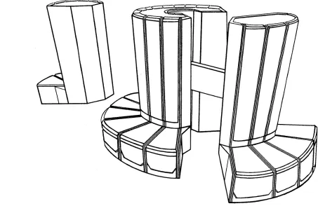
The multiple processors of the CRA Y X-MP EA computer system allows the use of multiple processing or multitasking techniques. Multiple processing allows several programs to run concurrently on multiple CPU s of a single mainframe. Multitasking allows two or more parts of a program to run in parallel, sharing a common memory space. The maximum configuration of the CRA Y X-MP EAl4 Computer System is shown in Figure 1-1. Mass storage devices (such as disk and tape drives) and front-end interfaces (FEls) can also be configured with the system.
System Overview CRAY X-MP EA Functional Description Manual
[image:14.612.81.534.156.450.2]The following subsections introduce the computer system components; later sections provide more detailed information on the lOS, FEls, SSD, and mass storage devices.
Figure 1-1. Maximum Configuration ofa CRA Y X-MP EAJ4 Computer System
CRAY X-MP EA MAINFRAME
eRA Y X-MP EA Functional Description Manual System Overview
Each CPU has a computation section consisting of operating registers, functional units, and a control section. The control section determines instruction issue and coordinates the three types of processing (vector, scalar, or address).
Refer to Section 2 for more specific information on the CRA Y X-MP EA mainframe.
I/O SUBSYSTEM
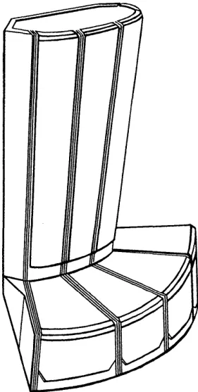
The CRA Y X-MP EA computer system includes an I/O Subsystem (lOS). The lOS chassis shown in Figure 1-2 has multiple I/O Processors (lOPs), a Buffer Memory, and required interfaces. It is designed for rapid data transfer between front-end computers, peripheral devices, storage devices, and the lOS's Buffer Memory, or between its Buffer Memory and the Central Memory of the eRA Y X-MP EA mainframe.
Figure 1-2. 110 Subsystem Chassis
[image:15.613.260.401.299.578.2]System Overview CRAY X-MP EA Functional Description Manual
The lOS also interfaces with the High-speed External (HSX) communications channel. The HSX channel connects peripheral equipment such as high-speed graphic devices to the CRA Y X-MP EA mainframe. Cray Research, Inc. (CRI) does not provide the external peripheral equipment but does provide the hardware connections and software drivers for the channel.
The HSX channel can also be connected to the SSD. With this configuration, data moves between Central Memory and the SSD over the conventional SSD channel and then transfers to the IOS/HSX channel.
Refer to Section 3 of this manual for more specific information on the lOS.
SSD SOLID-STATE STORAGE DEVICE
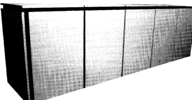
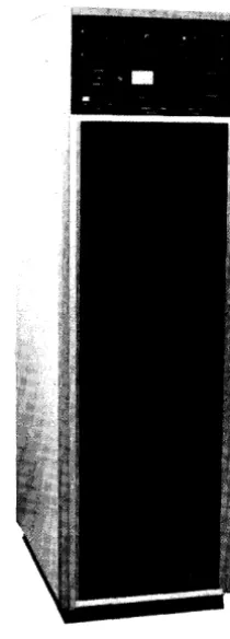
The SSD is an optional high-performance device used for temporary data storage. Figure 1-3 shows an SSD chassis. The SSD transfers data between the mainframe's Central Memory and the SSD through one or two special 1,OOO-Mbyte/s channels. The speed of these transfers depends on the SSD and CRA Y X-MP EA system configuration. The SSD can also be connected directly to an lOS over a lOO-Mbyte/s channel pair. The SSD-31 and SSD-51 are special versions of the SSD that are housed within the lOS chassis.
[image:16.617.208.405.397.701.2]Refer to Section 4 of this manual for specific information on the SSD.
CRAY X-MP EA Functional Description Manual System Overview
DISK STORAGE UNITS
For mass storage, the CRA Y X-MP EA computer system uses CRI Disk Storage Units (DSU s). A Disk Controller Unit (DCU) interfaces the DSU s to an lOP within the lOS. The lOP and the DCU can transfer data between the lOP and multiple DSU s without missing data or skipping revolutions even when all DSU s are operating at full speed. Refer to Section 5 of this manual for more specific information on Disk Storage Units.
COMMUNICATION INTERFACES
The CRAY X-MP EA mainframe is designed to communicate easily with front-end computer systems and computer networks.
Standard FEls connect either the 110 channels of the CRAY X-MP EA mainframe or the lOS to channels of front-end computers. This connection provides input data to the CRA Y X-MP EA computer system and receives output from it for distribution to peripheral equipment. An FEI compensates for differences in channel widths, machine word size, electrical logic levels, and control signals.
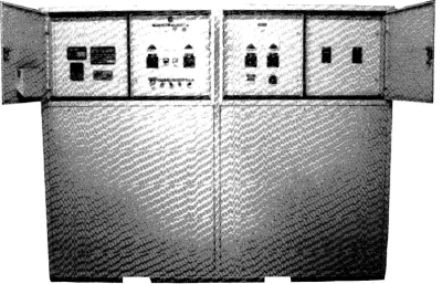
Some FEls are housed in stand-alone cabinets located near the host computer (refer to Figure 1-4), while some are installed directly into the front-end computer system. In either case, operation of the FEI is invisible to the Cray user.
An optional fiber-optic link is available for FEls that provides front-end connections of up to 3,280 ft (1,000 m) separation from the CRA Y X-MP EA computer system.
[image:17.617.225.440.490.704.2]The CRAY X-MP EA mainframe can be connected to computer networks directly or through a front-end computer system. Refer to Section 5 of this manual for specific information on Communication Interfaces.
System Overview CRAY X-MP EA Functional Description Manual
OPERATOR AND MAINTENANCE WORKSTATIONS
VMEbus technology is used to provide two workstations on the eRA Y X-MP EA computer system: the Operator Workstation (OWS) and the Maintenance Workstation (MWS). Both workstations run UNIX System V software. The OWS is a microcomputer system that provides the following:
• System operator interface
• System deadstart and master clear functions • Software maintenance utilities
• Local tape and local printer control • Time-of-day clock
• Remote access for software and hardware service • System monitoring acti vities requiring security
In addition, the OWS provides enhanced features such as the Ethernet interface, which can be used to link workstations in a network for multiple-system operators or sites. The OWS communicates with the eRA Y X-MP EA computer system through a 6-Mbyte/s I/O channel from an lOP in the lOS. The tape drives, disks, printer, and time-of-day clock are under direct control of the OWS.
The MWS is microcomputer system used for hardware maintenance and monitoring. The MWS provides the following:
• Off-line diagnostics for testing the mainframe, IOS,SSD, and peripherals • System deadstart and master clear functions
• System error logging
The MWS communicates with the eRA Y X-MP EA computer system through a 6-Mbyte/s channel from an lOP located in the lOS. The MWS monitors a special system error channel to detect and log system errors, such as double-bit memory errors.
POWER AND COOLING SUPPORT EQUIPMENT
eRA Y X-MP EA computer systems require support equipment for power and cooling. Power is supplied by a Motor Generator Set (MGS) and Power Distribution Unit (PDU). The remainder of this section defines and explains the various mainframe, lOS, and SSD support equipment. Refer to the appropriate Site Planning manuals listed in the Preface for more information on power and cooling requirements.
eRA
Y X-MP EA Functional Description Manual System OverviewTo control the intense heat created by the density of the circuitry, the CRA Y X-MP EA mainframe has a monitoring system consisting of PC boards and a system control panel. The monitoring system provides a method for the system attendant to observe these conditions. The monitoring system also functions as a backup system that can automatically shut down the mainframe if an abnormal condition develops and the system attendant fails to notice the condition. In addition to these automatic monitoring features, the AC output voltage on the MGS can be set from this panel.
[image:19.618.176.495.300.466.2]The refrigeration condensing unit (RCU) contains the major components of the refrigeration system used to cool the mainframe, lOS, and SSD. Heat is transferred from the RCU by customer-supplied cooling water. Figure 1-5 shows the RCU for a CRA Y X-MP EA 1, 2, or 4 processor mainframe only; the CRA Y X-X-MP EAlse uses a smaller RCU. The number ofRCUs needed is site dependent.
System Overview eRA Y X-MP EA Functional Description Manual
[image:20.617.129.529.174.431.2]Each Motor Generator (MG) converts primary power from commercial power mains to the 400-Hz power used by the mainframe, lOS, and SSD. The MG isolates these components from transients and fluctuations on the commercial power mains. A MG cabinet is shown in Figure 1-6.
Figure 1-6. Motor Generator Cabinet
eRA
Y X-MP EA Functional Description Manual System OverviewFigure 1-7 shows the PDUs for the CRA Y X-MP EN4 processor mainframe (left) and for
the CRAY X-MP EN1 and 2 processor mainframes, lOS, and SSD (right) .
.
.
-
~.'"
,.e~
. -
""."".
~ ~>
[image:21.618.145.370.145.443.2]-""~- w
CONTENTS
2 -eRA Y X-MP EA MAINFRAME ... 2-1 CPU SHARED RESOURCES ... 2-1 Central Memory ... 2-1 I/O Section ... 2-2 Interprocessor Communication Section ... 2-2 Real-time Clock ... 2-2 CPU COMPUTATION SECTION ... 2-3 Registers ... . . . .. 2-5 Address Registers ... 2-5
Scalar Registers 2-6
CPU INSTRUCTIONS ... 2-39 INSTRUCTION FORMATS ... 2-39 I-parcel Instruction Format with Discretej and k Fields ... 2-39 I-parcel Instruction Format with Combinedj and k Fields ... 2-40
2-parcel Instruction Format with Combinedj, k, and m Fields ... 2-41
2-parcel Instruction Format with Combined i,j, k, and m Fields ... 2-41
3-parcel Instruction Format with Combined m and n Fields ... 2-42
INSTRUCTION DIFFERENCES BETWEEN THE X-MODE AND Y-MODE ... 2-43 SPECIAL REGISTER VALUES ... 2-45 MONITOR MODE INSTRUCTIONS ... 2-45 SPECIAL CAL SYNTAX FORMS ... 2-45 CPU INSTRUCTION SUMMARY ... 2-46 Functional Units Instruction Summary ... 2-47 Functional Instruction Summary ... 2-47 Register Entry Instructions ... 2-48 Inter-register Transfer Instructions. . . .. 2-50 Memory Transfer Instructions ... 2-52 Integer Arithmetic Instructions ... 2-55 Floating-point Arithmetic Instructions ... 2-56 Logical Operation Instructions ... 2-59 Shift Instructions ... 2-62 Bit Count Instructions ... 2-63 Branch Instructions ... 2-64 Monitor Mode Instructions ... 2-65 CRA Y X-MP ENlse COMPUTER SYSTEM SPECIFICATION SHEETS ... 2-69 CRA Y X-MP EAJl COMPUTER SYSTEM SPECIFICATION SHEETS
CRA Y X-MP EAJ2 COMPUTER SYSTEM SPECIFICATION SHEETS CRA Y X-MP EAJ4 COMPUTER SYSTEM SPECIFICATION SHEETS
2-73 2-77 2-81
FIGURES
FIGURES (continued)
Figure 2-13. Vector-vector Operand Instructions 2-33
Figure 2-14. Vector-scalar Operand Instructions ... " 2-34
Figure 2-15. Vector Memory Instructions 2-34
Figure 2-16. Gather Instruction Example ... 2-35 Figure 2-17. Scatter Instruction Example ... 2-36 Figure 2-18. Compressed Index Example ... 2-36 Figure 2-19. General Format for Instructions ... " 2-39 Figure 2-20. I-parcel Instruction Format with Discrete} and k Fields ... 2-40 Figure 2-21. I-parcel Instruction Format with Combined} and k Fields ... 2-40
Figure 2-22. 2-parcel Instruction Format with Combined}, k, and m Fields ... 2-41
Figure 2-23. 2-parcel Instruction Format with Combined i, j, k, and m Fields ... 2-42
Figure 2-24. 2 -parcel Instruction Format for a 24-bit Immediate Constant with
Combined i,}, k, and m Fields ... 2-42
Figure 2-25. 3-parcel Instruction Format with Combined m and n Fields ... 2-43
TABLES
2 -
eRA v X-MP EA MAINFRAME
This section describes the major functional areas and special features of a CRA Y X-MP EA mainframe, and provides a summary of the Cray Assembly Language (CAL) instruction set.
CPU SHARED RESOURCES
The central processing units (CPU s) of the multiple processor CRA Y X-MP EA computer systems share several functional areas (or sections) of the mainframe. These sections are Central Memory, the I/O section, the Interprocessor Communication section, and the Real-time Clock. The following subsections describe these functional areas.
Central Memory
For multiple processor CRA Y X-MP EA computer systems, Central Memory is shared by the CPU s and the I/O section. Central Memory is divided into interleaved banks. This arrangement improves memory-access speed by allowing simultaneous and overlapping memory references. Refer to the specification mainframe sheets at the end of this section for more information on memory size and number of banks.
Each CPU in the system has four parallel memory ports. Each port performs specific functions, allowing different types of memory transfers to occur simultaneously. To further enhance memory operations, the bidirectional memory mode allows block read and write operations to occur concurrently.
The CRA Y X-MP EA computer system has built-in resolution hardware to minimize the delays caused by memory conflicts and to maintain the integrity of all memory references when conflicts occur. A memory conflict occurs when more than one reference is made to the same area of Central Memory.
To protect data, single-error correction/double-error detection (SECDED) logic is used in Central Memory and on data channels to or from Central Memory. When data is written into Central Memory, a checkbyte (an 8-bit Hamming t code) is generated for the word and stored with that word. When the word is read from Central Memory, the checkbyte and data word are processed to determine if any bits are altered. If no errors occur, the word is passed without modification.
CRAY X-MP EA Mainframe CRAY X-MP EA Functional Description Manual
If an error occurs, the 8 bits of the checkbyte are analyzed by the logic to find the number of altered bits. If only a single bit is altered, the correction logic resets that bit to the correct state and passes the corrected word on. The Memory Error flag in the Exchange Package sets to indicate that an error occurred, which can generate an interrupt. (Refer to ((Flag Register Field" in this section for more information on the Memory Error flag.) Error information is also sent to an error logger.
If more than a single bit is altered, the logic cannot correct the word and the results are unpredictable. When a double error is detected, the Memory Error flag in the Exchange Package sets to indicate an error occurred, which can generate an interrupt signal. Error information is also sent to an error logger.
1/0
Section
The I/O section is shared by the CPU s and may be equipped with a variety of high-performance channels for communication between the mainframe, the I/O Subsystem (lOS), and the SSD solid-state storage device. The latter two devices are high-speed data transfer devices designed to increase CRA Y X-MP EA mainframe processing speeds. Refer to the mainframe specification sheets at the end of this section for more information on channel types and transfer rates.
Interprocessor Communication Section
The interprocessor communication section of the mainframe contains clusters of shared registers for interprocessor communication and synchronization. Each cluster consists of Shared Address (SB), Shared Scalar (ST), and Semaphore (SM) registers.
The S8 and ST registers pass address and scalar information from one CPU to another, while the SM registers control activity between CPU s.
Each CPU Cluster Number (CLN) register determines which cluster of shared registers is accessed by a CPU. The cluster may be accessed by any CPU to which it is allocated in either user or system (monitor) mode. Any CPU in monitor mode can interrupt any other CPU and cause it to switch from user to monitor mode. The hardware also provides built-in detection of system deadlock within the cluster; a deadlock condition occurs when all CPU s in a cluster are holding issue on a Test and Set instruction.
Real-time Clock
CRA Y X-MP EA Functional Description Manual CRAY X-MP EA Mainframe
CPU COMPUTATION SECTION
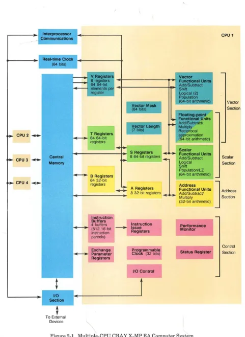
Each CPU is an identical, independent computing section consisting of operating registers, functional units, and an instruction control network (refer to Figure 2-1). The operating registers and functional units of each computing section are associated with three types of processing: address, scalar, and vector.
Address processing operates on internal control information such as loop counts, addresses, and indexes. This processing is done by Address (A) registers and dedicated integer arithmetic functional units.
Address information flows from Central Memory, instruction values, or control registers to A registers. Information in the A registers is distributed to various parts of the control network for use in controlling the scalar, vector, and I/O operations. The A registers can also supply operands to two integer functional units. The units generate address and index information and return the result to the A registers. Address information can also be transmitted to Central Memory from the A registers.
Scalar and vector processing are performed on data; scalar processing occurs sequentially and uses one operand or operand pair to produce a single result. Scalar processing is performed using Scalar (S) registers, several functional units dedicated solely to scalar processing, and additional floating-point functional units shared with vector operations.
Vector processing allows a single operation to be performed concurrently on a set (or vector) of operands, repeating the same function to produce a series of results. Vector processing is performed by Vector (V) registers, several functional units dedicated solely to vector processing, and additional floating-point functional units supporting both scalar and vector operations.
The main advantage of vector processing over scalar processing is that it eliminates instruction start-up time for all but the first operand. Start-up time for vector operations is short, therefore vector processing is more efficient than scalar processing for vectors containing as few as two elements. Register-to-register vector instructions eliminate the problem of memory conflicts.
Data flow in a computing section is from Central Memory to registers and from registers to functional units. Results flow from functional units to registers and from registers to Central Memory or back to functional units. Data flows along either the scalar or vector path, depending on the processing mode. An exception is that scalar registers can provide one required operand for some vector instructions.
The computation section performs integer or floating-point arithmetic operations. Integer arithmetic is performed in two's complement mode. Floating-point quantities have signed magnitude representation.
CRAY X-MP EA Mainframe CRAY X-MP EA Functional Description Manual
Interprocessor Communications
~ CPU 2 . . . .
~ CPU 3 . . . .
~ CPU4 . . . .
Real-time Clock (64 bits)
Central Memory
110 Section
t
To External
V Registers
8 registers ~r---~-+t
64 64-bit
Vector
Functional Units Add/Subtract Shift
~--f elements pe register
T Registers ~---l~ 54 54-bit
registers
I
Vector Mask (64 bits)I
Vector Length(7 bits)
Logical (2)
Population (64-bit arithmetic)
Floating-point
~ FunctIOnal Units ~ Add/Subtract!
. Multiply Reciprocal
approximation
(64-bit arithmetic)
_I~~ .
W
Scalar~---+. S Registers ,. Functional Units
~ B Registers 5432-bit
registers
Instruction Buffers 4 buffers (51215-bit instruction parcels)
Exchange Parameter Registers
l.:J
8 54-bit registers I ~ Add/Subtract Logical- .
Shift Population/LZ (54-bit arithmetic) Address A Registers Functional Units 8 32-bit registers __ ~ Add/Subtract!~ -~ Multiply
(32-bit arithmetic)
-
-Instruction Performance Issue Monitor Registers
~
-Programmable
Clock (32 bits) Status Register
I
110 Control
[image:30.609.65.547.52.712.2]Devices ,
Figure 2-1. Multiple-CPU CRA Y X-MP EA Computer System
CPU 1
Vector Section
Scalar Section
]
Address Section
CRAY X-MP EA Functional Description Manual CRAY X-MP EA Mainframe
Registers
Floating-point instructions include addition, subtraction, multiplication, and reciprocal approximation. The reciprocal approximation instructions can be used with a multiplication instruction sequence to perform a floating-point division operation. The instruction set includes logical operations for AND, inclusive OR, exclusive OR, exclusive NOR, and a mask-controlled merge operatioil. Shift operations allow the manipulation of either 64-bit or 128-bit operands to produce 64-bit results. With the exception of address integer arithmetic, most operations are implemented in vector and scalar instructions.
The integer product is a scalar instruction designed for index calculation. Full indexing capability is possible throughout memory in either scalar or vector mode. The index can be positive or negative in either mode. Indexing allows matrix operations in vector mode to be performed on rows or on the diagonal as well as allowing conventional column-oriented operations.
Population and parity count instructions are provided for both vector and scalar operations. An additional scalar operation is the leading zero count.
Each CPU has three primary and two intermediate sets of registers. The primary sets of registers are the Address (A), Scalar (S), and Vector (V) registers. These registers are considered primary because Central Memory and the functional units can access them directly.
For the A and S registers, an intermediate level of registers exists. These registers are not accessible to the functional units, but act as a buffer for the primary registers. Block transfers of consecutive locations are possible between these registers and Central Memory so that the number of memory reference instructions required for scalar and address operands is greatly reduced. Data can then be moved from intermediate registers to the primary register when needed. The intermediate registers that support the A registers are referred to as intermediate address (B) registers. The intermediate registers that support S registers are referred to as intermediate scalar (T) registers.
Address Registers
CRAY X-MP EA Mainframe CRAY X-MP EA Functional Description Manual
Address processing in the CRA Y X-MP EA computer system operates in two modes: the X-mode and the V-mode. In the X-mode, the A registers, B registers, and the address functional units are limited to 24 bits, as in earlier models of the CRA Y X-MP computer systems. Only 1- and 2-parcel instructions run in the X-mode. In the V-mode, the A registers, B registers, and address functional units run at a full 32-bit width and the instruction set is expanded to include 3-parcel instructions. Refer to "Instruction Differences Between the X-mode and Y-mode" later in this section for more information on these modes and instructions.
Scalar Registers
Each CPU contains 64 S registers; each register is 64-bits wide. The S registers are the principal scalar registers for a CPU. Scalar registers serve as the source and destination for scalar arithmetic and logical instructions. Scalar registers can also provide an operand for some vector operations.
Each CPU contains 64 T registers; each register is 64 bits wide. The T registers are used as intermediate storage for the S registers. Data is transferred between T registers and Central Memory and between T and S registers.
Vector Registers
Each CPU contains eight Vector (V) registers. Each V register consists of 64 elements; each element is 64-bits wide. The V registers serve as the source and destination for vector arithmetic and logical instructions. Successive elements from a V register enter a functional unit in successive CPs with a single instruction.
The effective length of a V register for any operation is controlled by the program-selectable Vector Length (VL) register. The VL register is a 7-bit register specifying the number of vector elements processed by vector instructions. The contents range from bits 08 through 778.
The Vector Mask (VM) register allows for the logical selection of particular elements of a vector. The VM register has 64 bits, each corresponding to a word element in a V register. The high-order bit of the VM register corresponds to element 0 of the V register, while the low-order bit corresponds to element 63. The mask is used with vector merge and test instructions to perform operations on individual elements.
Refer to "Vector Processing" later in this section for more specific information.
Functional Units
Instructions other than simple transmits or control operations are performed by specialized hardware known as functional units. gach unit implements an algorithm or a portion of the instruction set. Most functional units have independent logic and can operate simultaneously.
All functional units perform algorithms in a fixed time; delays are impossible after the operands are delivered to the unit (except those caused by memory conflicts). ~-'unctional
CRA Y X-MP EA Functional Description Manual CRA Y X-MP EA Mainframe
can enter a functional unit each CP even though the functional unit time can be more than 1 CPo Refer to uPipelining and Segmentation" and tfFunctional Unit Independence" later in this section for more information on segmentation, pipe lining, and functional unit independence.
There are four types of functional units: address, scalar, vector, and floating-point. The first three functional units function with one of the primary register types (A, S, and V) to support the address, scalar, and vector processing modes. The floating-point functional units, support either scalar or vector operations and accept operands from or deliver results to S or V registers. In addition, Central Memory can also act as a functional unit for vector operations.
Address Functional Units
Address functional units perform integer arithmetic on operands obtained from A registers and deliver the results to an A register (integer arithmetic is explained later in this section). The arithmetic is two's complement. The following list describes the two Address functional units.
• The Address Add functional unit performs integer addition and subtraction; subtraction is performed by using two's complement arithmetic. Overflow is not detected.
• The Address Multiply functional unit forms an integer product from two operands. No rounding is performed and overflow is not detected. The unit returns only the least significant bits of the product.
Scalar Functional Units
Scalar functional units perform operations on operands obtained from S registers and usually deliver the results to an S register (integer arithmetic is explained later in this section). The exception is the Population/Parity/Leading Zero Count functional unit, which delivers its result to an A register.
The Scalar Add, Scalar Shift, Scalar Logical, and Scalar Population/Parity/Leading Zero functional units are used exclusively with scalar operations and are described below. Three additional functional units are used for both scalar and vector operations. They are described in the "Floating-point Functional Units" subsection. The following list describes these four Scalar functional units:
• The Scalar Add functional unit performs integer addition and subtraction; subtraction is performed by using two's complement. Overflow is not detected. • The Scalar Shift functional unit shifts the entire contents of an S register or
shifts the contents of two linked S registers into a single resultant S register. Shifts are end-off with zero fill. Shift counts are obtained from an A register or from a field of the instruction.
CRA Y X-MP EA Mainframe CRAY X-MP EA Functional Description Manual
• The Scalar Population/Parity/Leading Zero functional unit counts the number of bits in an S register having a value of 1 in the operand, and then depending on the instruction issued, returns the value either as a population or population parity count to an A register. For the leading zero function, it counts the number of 0 bits preceding a 1 bit in the operand from left to right; the operand is obtained from an S register and the result is delivered to an A register.
Vector Functional Units
Vector functional units perform operations on operands obtained from one or two V registers or from a V register and an S register. The Vector Add and Logical functional units require two operands, while the Vector Shift and Population/Parity functional units require only one operand. Results from a Vector functional unit are delivered to a V register.
Successive operand pairs are transmitted each CP to a functional unit. The corresponding result emerges from the functional unit n CPs later, where n is the functional unit time and is constant for a given functional unit. The VL register determines the number of operands or operand pairs to be processed by a functional unit. Refer to "Special Features of the CRA Y X-MP EA Computer System" later in this section for more information on vector processing, chaining, and other special vector-processing features.
The functional units described in this subsection are used exclusively with vector operations. Three functional units are used with both vector and scalar operations and are described in the following "Floating-point Functional Units" subsection. The following list describes the five Vector functional units.
• The Vector Add functional unit performs integer addition and subtraction for a vector operation and delivers the results to elements of a V register. Subtraction is performed by using two's complement arithmetic. Overflow is not detected.
• The Vector Shift functional unit shifts the entire contents of a V register element or the value formed from two consecutive elements of a V register. Shift counts are obtained from an A register. All shifts are end-off with zero fill.
• The Full Vector Logical functional unit performs a bit-by-bit manipulation of vector elements for specific instructions. The Full Vector Logical functional unit also performs vector register merge, compressed index, and logical operations associated with the vector mask instructions.
CRAY X-MP EA Functional Description Manual CRAY X-MP EA Mainframe
• The Vector Population/Parity functional unit counts the 1 bits in each element of the source V register; the result is the population count. This population count can be an odd or an even number, as shown by its low-order bit. The Vector Population Count instruction delivers the total population count to elements of the destination V register. The Vector Population 00unt Parity instruction delivers the low-order bit of the count to the destination V register.
Floating-point Functional Units
Three floating-point functional units perform floating-point arithmetic for scalar and vector operations. When a scalar instruction issues, operands are obtained from S register(s) and results are delivered to an S register. For most vector instructions, operands are obtained from pairs of V registers or from an S register and a V register. Results are delivered to a V register. An exception is the Reciprocal Approximation functional unit, which requires only one input operand. When a Floating-point functional unit is used for a vector operation, the general description of a vector functional unit applies. The following list describes the three floating-point functional units.
• The Floating-point Add functional unit performs addition or subtraction of operands in floating-point format. The final result is normalized even when operands are not normalized. (Refer to "Normalized Floating-point Numbers" later in this section for more information on normalized numbers.) Out-of-range exponents in operands (not in result values) are detected.
• The Floating-point Multiply functional unit issues instructions that provide for full- and half-precision multiplication of operands in floating-point format and for computing two minus a floating-point product for reciprocal iterations. The half-precision product is rounded; the full-precision product can be rounded or not rounded. This functional unit can also generate a 32-bit integer product when operating in X-mode or V-mode.
Input operands are assumed to be normalized. The Floating-point Multiply functional unit delivers a normalized result only if both input operands are normalized.
Out-of-range exponents in operands are detected. If both operands have zero exponents, however, the result is an integer product, is not normalized, and is not out-of-range.
• The Reciprocal Approximation functional unit finds the approximate reciprocal of an operand in floating-point format. The input operand must be normalized. The high-order bit of the coefficient is not tested, but must be a 1. Out-of-range exponents are detected.
Functional Unit Operations
CRAY X-MP EA Mainframe CRA Y X-MP EA Functional Description Manual
Logical Operations
Scalar and vector logical units perform bit-by-bit manipulation of 64-bit quantities. Instructions are provided for forming logical products, sums, differences, equivalencies and merges.
A logical product is the AND function, which is shown below: Operand 1: 101 0
Operand 2: 1100 Result: 1 0 0 0
A logical sum is the inclusive OR function, which is shown below: Operand 1: 101 0
Operand 2: 1100 Result: 1 1 1 0
A logical difference is the exclusive OR function, which is shown below: Operand 1: 101 0
Operand 2: 1 1 0 0 Result: 0 1 1 0
A logical equivalence is the exclusive NOR function,which is shown below: Operand 1: 101 0
Operand 2: 1 100 Result: 1 0 0 1 .
The merge operation uses two operands and a mask to produce results as shown below. The bits of operand 1 pass where the mask bit is a l. The bits of operand 2 pass where the mask bit is a O.
Operand 1: 1 0 1 0 1 0 1 0 Operand 2: 1 100 1 100 Mask: 1 1 1 1 0 0 0 0 Result: 1 0 1 0 1 1 0 0
Integer Arithmetic
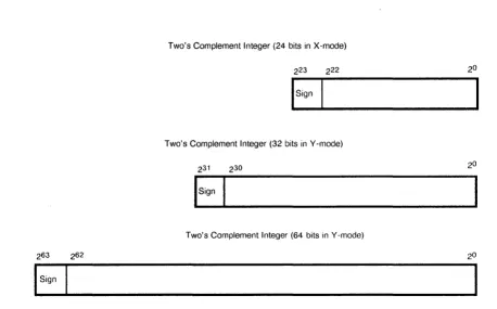
All integers, whether 24, 32, or 64 bits, are represented in the registers as shown in Figure 2-2. The Address Add and Multiply functional units perform 24-bit arithmetic in X-mode and 32-bit arithmetic in Y -mode (refer to "Instruction Diffcrences Between the X-mode and Y-mode" later in this section for morc information on these modes). The Scalar Add and Vector Add functional units perform 64-bit arithmetic.
CRA Y X-MP EA Functional Description Manual CRAY X-MP EA Mainframe
Two's Complement Integer (24 bits in X-mode)
Two's Complement Integer (32 bits in Y -mode)
Two's Complement Integer (64 bits in Y -mode)
[image:37.613.99.557.64.349.2]I
SignFigure 2-2. Integer Data Formats
The Floating-point Multiply functional unit recognizes the condition under which both operands have zero exponents as a special case; it is treated as an integer multiplication operation, and a complete multiplication operation is performed with no truncation as long as the total number of bits in the two operands does not exceed 48-bit positions. To multiply two integer numbers together, set each operand's exponent equal to zero and place each 24-bit integer value in bit positions 247 through 224 of the operand's coefficient field. To ensure accuracy, the least significant 24 bits must be O.
When the Floating-point Multiply functional unit has performed the operation, it returns the high-order 48 bits of the product as the result coefficient and leaves the exponent field as O. The result is a 48~bit quantity in bit positions 247 through 20; no normalization shift of the result is performed.
As shown in Figure 2-3, if operand 1 is 48 and operand 2 is 68, a 48-bit result of 308 is produced. Bit 263 is subject to the usual rules for multiplying signs and the result is a sign-magnitude integer. The format of integers expected by both the hardware and software is two's complement, not sign-magnitude, therefore negative products must be converted to two's complement form.
The second multiplication method is used when the operands are greater than 24 bits in length. Multiplication is done by software forming multiple partial products and then shifting and adding the partial products.
A second integer multiplication operation performs a 32-bit multiply of the contents ofSj register and the contents of V k to Vi. The operands must be left-shifted before the operation begins. The operand contained in Sj must be left-shifted 3110 places, leaving the operand in bit positions 262 through 231 ; bit positions 230 through 20 must be equal to
CRA Y X-MP EA Mainframe CRAY X-MP EA Functional Description Manual
The operand contained in Vk must be left-shifted 1610 places, leaving the operand in bit positions 247 through 216; bit positions 215 through 20 must be equal to 0 to ensure accuracy. The result of the multiply is right justified into positions 231 through 20, while positions 232 through 263 are zero filled.
Operand 1 0
Operand 2 0
Result
o
(Sj) .:
(Vk)
0 0 04 Must be 0 to ensure
correct product
Must be 0 to ensure
0 0 06 correct product
[image:38.613.70.550.149.684.2]o
o
030Figure 2-3. 24-bit Integer Multiply Performed in Floating-point Multiply Functional Unit
Operand ,
Operand
Must be 0 to ensure correct product
Must be 0 to ensure correct product
Result [ 0 - - - 0
I ...
f---
ResultFigure 2-4. 32-bit Integer Multiply Performed in Floating-point Multiply Functional Unit
[image:38.613.141.545.170.326.2]CRA Y X-MP EA Functional Description Manual CRA Y X-MP EA Mainframe
Floating-point Arithmetic
Floating-point arithmetic is used by the scalar and vector instructions. The following subsections explain the floating-point data format, exponent ranges, normalized floating-point numbers, floating-point range errors, the floating-point addition, multiplication, and division algorithms, and double-precision numbers.
Floating-point Data Format
Floating-point numbers are represented in a standard format throughout the CPU; this format is shown in Figure 2-5. The format has three different fields: coefficient sign, exponent, and coefficient.
Coefficient Sign
Exponent
Binary Point 248
!
247Coefficient
Figure 2-5. Floating-point Data Format
This format is a packed representation of a binary coefficient and an exponent (power of two). The coefficient sign is located in bit position 263 and is separated from the rest of the coefficient. If this bit is equal to 0, the coefficient is positive; if this bit is equal to 1, the coefficient is negative. The exponent is represented as a biased integer number in bit positions 262 through 248 ; each exponent is biased by 400008. Bit 261 is the the sign of the exponent; a 0 indicates a positive exponent, while a 1 indicates a negative exponent. Bit 262 is the bias of the exponent.
The coefficient is a 48-bit signed fraction; the sign of the coefficient is located in bit position 263. Because the coefficient is in sign-magnitude format, it is not complemented for negative values. A normalized floating-point number has a 1 in the 247 bit position, while a not normalized floating-point number has a 0 in this bit position (normalized numbers are discussed in more detail later in this section).
Figure 2-6 and the following steps show the relationship between the bias, exponent, and coefficient.
To convert a floating-point number to its decimal equivalent, refer to the following example:
1. Subtract the bias from the exponent to get the integer value of the exponent: 400118
eRA Y X-MP EA Mainframe eRA Y X-MP EA Functional Description Manual
Coefficient Sign
400118
Exponent
Binary Point
248
!
24756320000000000008
Normalized Coefficient
Figure 2-6. Internal Representation of Floating-point Number
2. Multiply the normalized coefficient by the power of 2 indicated in the exponent to get the result:
0.5634s X 29 = 563.40s = 371.510
A zero value or an underflow result is not biased and is represented as a word of all Os. A negative 0 is not generated by any Floating-point functional unit, except if a negative 0 is one operand going into the Floating-point Multiply or Floating-point Add functional unit.
Exponent Ranges
The exponent portion of the floating-point format is represented as a biased integer in bits 262 through 2 4S. The bias that is added to the exponents is 40000s, which represents an exponent of 20. Figure 2-7 shows the biased and unbiased exponent ranges.
200008
JOt(
_220000
Biased Exponent Range
Negative Range Positive Range
400008
Unbiased Exponent Range
Figure 2-7. Biased and Unbiased Exponent Range
577778
217777
CRAY X-MP EA Functional Description Manual CRAY X-MP EA Mainframe
Normalized Floating-point Numbers
A nonzero floating-point number is normalized if the most significant bit of the coefficient, bit 247 , is nonzero. This condition implies that the coefficient has been shifted as far left as possible and that the exponent has been adjusted accordingly, therefore a normalized floating-point number has no leading Os in its coefficient. The exception is a normalized floating-point 0, which is all Os.
When a floating-point number is created by inserting an exponent of 400608 and a 48-bit integer word into the coefficient, the result should be normalized before it is used in a floating-point operation. Normalization is accomplished by adding the not normalized floating-point operand to
o.
The Reciprocal Approximation functional unit must receive normalized numbers to produce correct results; using not normalized numbers will produce inaccurate results. The Floating-point Multiply functional unit does not require normalized numbers to get correct results; however, more accurate results occur when normalized numbers are used.
The Floating-point Add functional unit does not require normalized numbers to get correct results. The Floating-point Add functional unit does, however, automatically normalize all its results; not normalized floating-point numbers may be routed through this functional unit to take advantage of this process.
Floating-point Range Errors
To make sure that the limits of the functional units are not be exceeded, a range check is made on the exponent of each floating-point operand for overflow and underflow conditions. In the Floating-point Add and Multiply functional units, bits 261 and 262 are checked; if both are equal to 1, the exponent is equal to or greater than 600008 and an overflow condition is detected. The calculated coefficient is reported, but the result exponent is set to 600008 and the Floating-point Error mode flag (lFP) is set (refer to Figure 2-8).
When an overflow condition is detected, an interrupt occurs only if the Interrupt on IFP flag is set in the Mode register and the system is not in Monitor mode. The IFP flag can be set or cleared by a user mode program.
To check for an underflow condition in the Floating-point Add and Multiply functional units, bits 261 and 262 are checked; if both are equal to 0, then the exponent is less than or equal to 177778 and an underflow condition is detected. No flag is set, but the exponent and coefficient are both set to 0 (refer to Figure 2-8).
In the Reciprocal Approximation functional unit, the exponent is complemented and the value of 2 is added before the operation proceeds. When the check is made in a reciprocal approximation operation, the exponent must be equal to or greater than 600028 to have an overflow condition occur. In this case, the calculated coefficient is reported, but bit
247 is set to 0, the exponent is set to 600008, and the IFP is set (refer to Figure 2-9).
CRAY X-MP EA Mainframe CRAY X-MP EA Functional Description Manual
but bit 247 is set to 0, the exponent is set to 600008, and the IFP is set (refer to Figure 2-9).
263 262 248 247 2°
Overflow 0 600008 Calculated
Sign Exponent Coefficient, Flag Set
263 262 248 247 2°
Underflow 0 0
01
0 0Sign Exponent Coefficient, No Flag Set
Figure 2-8. Floating-point Add and Multiply Range Errors
263 262 248 247 20
Overflow 0 600008 Calculated
I
Sign Exponent Coefficient, 247 = O. Flag Set
Underflow 0 600008 Calculated
[image:42.615.118.552.210.516.2]Sign Exponent Coefficient, 247 = 0, Flag Set
Figure 2-9. Floating-point Reciprocal Approximation Range Errors
Floating-point Addition Algorithm
CRAY X-MP EA Functional Description Manual CRAY X-MP EA Mainframe
After the two coefficients are equalized, they are added together. Two conditions are analyzed to determine whether an addition or subtraction operation occurs. The two conditions are the sign bits of the two coefficients and the type of instruction (an add or subtract) issued. The following list shows how the operation is determined.
• If the sign bits are equal and an addition instruction is issued, an addition operation is performed.
• If the sign bits are not equal and an addition instruction is issued, a subtraction operation is performed.
• If the sign bits are equal and a subtraction instruction is issued, a subtraction operation is performed.
• If the sign bits are not equal and a subtraction instruction is issued, an addition operation is performed.
The last operation performed is normalizing the results. To normalize the result, the coefficient is left-shifted by the number of leading Os (the coefficient is normalized when bit 247 is a 1). The exponent must also be decremented accordingly. If a carry across the binary point occurs during an addition operation, the coefficient is right-shifted by 1 and the exponent increases by 1. If a carry across the binary point occurs during a subtraction operation, an end-around carry occurs.
The normalization feature of the Floating-point Add functional unit can normalize any floating-point number; pair it with a zero operand and send them through the Floating-point Add functional uni t.
A range check is performed on operands; refer to "Floating-point Range Errors" earlier in this section for more information on how the result is checked.
Floating-point Multiplication Algorithm
The Floating-point Multiply functional unit receives two floating-point operands from either an S or V register. The signs of the two operands are exclusive ORed, the exponents are added together, and the two 48-bit coefficients are multiplied together. If the coefficients are both normalized, multiplying them together produces a full product of either 95 or 96 bits. A 96-bit product is normalized as generated, while a 95-bit product requires a left-shift of one to generate the final coefficient. If the shift is done, the final exponent is reduced by 1 to reflect the shift.
Because the result register (an S or V register) can hold only 48 bits in the coefficient, only the upper 48 bits of the 96-bit result are used. The lower 48 bits are never generated. The following paragraphs describe the truncation process used to compensate for the loss of bits in the product. It assumes no shift was required to generate the final product: power of two designators are used.
CRA Y X-MP EA Mainframe CRA Y X-MP EA Functional Description Manual
The effect of the truncation without compensation is at most a result coefficient 1 smaller than expected. With compensation, the results range from 1 too large to 1 too small in the 2-48 bit position, with approximately 99% of the values having zero deviation from what would have been generated had a full 96-bit product been present. The multiplication is commutative; that is, A X B
=
B X A.Rounding is optional, while truncation compensation is not. The rounding method used adds a constant so that it is 50% high (0.25 X 2-48 ; high) 38% of the time and 25% low (0.125 X 2-48 ; low) 62% of the time, resulting in a near-zero average rounding error. in a full-precision rounded multiplication operation, 2 round bits are entered into the summation at bit positions 2-50 and 2-51 and allowed to multiply.
For a half-precision multiplication operation, round bits are entered into the summation at bit positions 2-32 and 2-31. A carry resulting from this entry is allowed to multiply up and the 29 most significant bits of the normalized result are transmitted back.
The variations results from this truncation and rounding fall within the following range: -0.23 X 2-48 to
+
0.57 X 2-48or
-8.17 X 10⁻¹⁶ to
+
20.25 X 10⁻¹⁶With a full 96-bit product and rounding equal to one-half the least significant bit, the following variation would be expected;
-0.5 X 2-48 to
+
0.5 X 2-48Floating-point Division Algorithm
The eRA Y X-MP EA computer system does not have a single functional unit that is dedicated to the division operation; the Floating-point Multiply and Reciprocal Approximation functional units together carry out the algorithm. The following paragraphs explain how the algorithm is determined and how it is used in the functional units.
Obtaining a quotient for two floating-point numbers involves two general steps. First to solve the equation AlB, the B operand is sent through the Reciprocal Approximation functional unit to obtain its reciprocal, liB. Then, this result is sent, along with the A operand to the Floating-point Multiply functional unit to obtain the product of A X liB.
The steps involved in a division operation are not that general, however. The Reciprocal Approximation functional unit uses an application of Newton's method for approximating the real root of an arbitrary equation, F(x)
=
0, to find reciprocals.To find the reciprocal, the equation F(x) = lIx -B must be solved. To do this, a number A must be found so that F(A) = 11 A - B =
o.
That is, the number A is the root of the equation 1Ix -B = O. This method requires an initial approximation (or guess, which is shown as xo in Figure 2-10) sufficiently close to the true root (which is shown as Xt inCRAY X-MP EA Functional Description Manual CRAY X-MP EA Mainframe
The intercept of this tangent line becomes the second approximation, Xl. This process is repeated, using tangent line 2 to obtain X2, and so on. The following iteration equation is derived from this process:
y
[image:45.615.146.518.159.419.2]y=F(x)
Figure 2-10. Newton's Method
Tangent line 1 (Xo. F(Xo))
Tangent line 2
x
In the equation, x(x + 1) is the next iteration, Xi is the current iteration, and B is the
divisor. Each X(i + 1) is a better approximation than Xi to the true value, Xt. The exact
answer is generally not obtained at once because the correction term is not exact. The operation is repeated until the answer becomes sufficiently close for practical use.
The eRA Y X-MP EA mainframe uses this approximation technique based on Newton's method. A hardware look-up table provides an initial guess, xo, to start the process. The following iterations are then calculated:
Iteration 1
2
3
Operation Description
The first approximation is done in the Reciprocal Approximation functional unit and is accurate to 8 bits.
The second approximation is done in the Reciprocal Approximation functional unit and is accurate to 16 bits.