i
DEVELOPMENT OF A DC-DC BUCK BOOST CONVERTER USING FUZZY LOGIC CONTROL
FATHI SHABAN JABER
A thesis submitted in
fulfillment of the requirement for the award of the Degree of Master of Electrical Engineering
Faculty of Electrical and Electronic Engineering Universiti Tun Hussein Onn Malaysia
v
ABSTRACT
A fuzzy controller of DC-DC Buck-boost converter is designed and presented in this project. In order to control the output voltage of the buck-boost converter, the controller is designed to change the duty cycle of the converter. The mathematical model of buck-boost converter and fuzzy logic controller are derived to design simulation model. The simulation is developed on Matlab simulation program. To verity the effectiveness of the simulation model, an experimental set up is developed. The buck-boost circuit with mosfet as a switching component is developed. The fuzzy logic controller to generate duty cycle of PWM signal is programmed. The simulation and experimental results show that the output voltage of the buck-boost converter can be controlled according to the value of duty cycle
vi
ABSTRAK
Sebuah pengawal alat peranti fuzzy Buck-boost DC-DC direka dan dihasilkan dalam projek ini. Untuk mengendalikan tegangan output dari alat peranti buck-boost, alat pengawal direka untuk menukar kerja-kerja kitaran dari alat peranti. Model matematik dari peranti buck-boost dan pengawal logic fuzzy yang diperolehi dan direka digunakan sebagai model simulasi. Simulasi dibangunkan dalam program Matlab. Untuk
vii
TABLE OF CONTENTS
CHAPTER TITLE PAGE
THESIS STATUS CONFIRMATION SUPERVISOR’S DECLARATION
TITLE PAGE i
DECLARATION ii
DEDICATION iii
ACKNOWLEDGEMENT iv
ABSTRACT v
ABSTRAK vi
TABLE OF CONTENTS vii
LIST OF TABLES x
LIST OF FIGURES xi
CHAPTER 1 INTRODUCTION 1
1.1 Project’s Background 1
1.2 Problem Statements 2
1.3 Project’s Objectives 3
viii
CHAPTER 2 LITERATURE REVIEW 4
2.1 Introduction 4
2.2 DC-DC Convertors 4
2.2.1 Functions of DC-DC converters 5
2.3 Buck-boost converter 6
2.4 Fuzzy Logic Controller 11
2.5 Structure of Fuzzy Logic 12
2.5.1 Input 13
2.5.2 Fuzzification 13
2.5.3 Rule Base 13
2.5.4 Defuzzification 13
2.5.5 Output 14
2.6 eZdspTM F2808 board 14
2.6.1 Key Features of the eZdspTM F280814 15
CHAPTER 3 METHODOLOGY 16
3.1 Introduction 16
3.2 Proposed design 18
3.3 Fuzzy logic controller for proposed system 20
3.4 Fuzzy Logic Toolbox 24
3.4.1 FIS Editor 26
3.4.2 Membership Function Editor 28
3.4.3 Rule Editor 31
3.4.4 Rule Viewer 32
3.5 Software development and implementation 33
3.6 Buck boost converter design using Matlab Simulink 35
3.7 Fuzzy logic controller using Matlab Simulink 35
ix
CHAPTER 4 RESULTS AND ANALYSIS 45
4.1 Introduction 45
4.2 Calculation method 45
4.3 Software simulation Result 47
4.3.1 Result of Matlab Simulink software 47
4.4 Simulation of the proposer system 48
4.5 Result and discussion 49
4.6 Hardware Analysis 54
4.6.1 Generate PWM switching signal 55
4.6.2 Drive circuit 56
4.6.3 Results and analysis of the Buck Boost converter circuit 57 4.6.4 Discussion 61
CHAPTER 5 CONCLUSION AND RECOMMENDATION 63 5.1 Project’s Conclusion 63
xi
LIST OF FIGURES
2.1 buck-boost converter diagram 6
2.2 equivalent circuits of Buck boost converter 7
2.3 waveforms of buck boost converter 8
2.4 Structure of fuzzy logic controller 12
2.5 eZdspTM F2808 board 15
3.1 Flowchart of project 17
3.2 3.3 3.4 3.5
Block diagram of the proposed system Error (input)
Change in Error (input) Change in Duty cycle (output)
19 21 21 23
3.6 Fuzzy Inference System 25
3.7 FIS editor 27
3.8 Membership Function Editor 28
3.9 FIS Editor for Membership Function variable 29
3.10 Rule Editor 31
3.11 Flowchart of software development 34
3.12 buck-boost converter block 35
3.13 fuzzy logic controller simulation 37
3.14 Flowchart of Hardware development 38
3.15 PWM duty cycle control via period change 39
3.16 PWM1A outputs for the specified pins of ePWM Output Blocks 40
3.17 P8 Connector of eZdpTM F2808 board 41
xii
3.19 Real-Time Workshop code generation options 43
4.1 Simulink Model of the proposed system 49
4.2 The output voltage (-12 V) at duty cycle 0.5 50
4.3 The output voltage (-8 V) at duty cycle 0.4 50
4.4 The output voltage (-5.14 V) at duty cycle 0.3 51
4.5 The output voltage (-3 V) at duty cycle 0.2 51
4.6 4.7 4.8 4.9
The output voltage (-1.3 V) at duty cycle 0.1 The output voltage (-18 V) at duty cycle 0.6 The output voltage (-28 V) at duty cycle 0.7 Block diagram of the hardware development
52 52 53 54
4.10 PWM duty cycle control via period change 55
4.11 Output waveform of PWM when the duty cycle is 0.5 56
4.12 Shows the driver circuit 57
4.13 Buck Boost converter circuit 57
4.14 Experimental Circuit 58
4.15 Waveform of the output voltage and pulse signal when the duty cycle, 0.1
59
4.16 Waveform of the output voltage and pulse signal when the duty cycle, 0.2
59
4.17 Waveform of the output voltage and pulse signal when the duty cycle, 0.3
60
4.18 Waveform of the output voltage and pulse signal when the duty cycle, 0.4
60
4.19 Waveform of the output voltage and pulse signal when the duty cycle, 0.5
x
LIST OF TABLES
TABLE NO. TITLE PAGE
3.1 Fuzzy Rule base 22
3.2 P4/P8, I/O Connectors 42
4.1 The values of output voltage, minimum inductance, minimum 46 Capacitance
CHAPTER 1
INTRODUCTION
1.1 Project background
Nowadays, fuzzy logic controllers have been used in many industrial applications and also power electronic drives in order to improve performance without having to develop mathematical model of the system. The main feature of a fuzzy controller is that it can convert the linguistic control rules based on expert knowledge into automatic control strategy. So it can be applied to control systems with unknown or unmodelled dynamics. (Ozdemir, 1997)
2
Buck Boost converter is an intriguing subject from the control point of view, due to its intrinsic non-linearity. Common control approaches like voltage control and current injected control, require a good knowledge of the system and accurate tuning in order to obtain performances.
The fuzzy logic approach has been proposed to converters. Its major advantage is that expert knowledge can regulate the output voltage of the switching DC–DC Buck boost converter be incorporated into the fuzzy controller using simple linguistic rules to achieve the control objective without involving the converter’s mathematical models. (SO W.C., 1996) and (LIN P.Z., 2006) The Fuzzy logic controller are designed based on dimensional rule table using voltage error and change in voltage error as input variables and change in duty cycle as control output. (S. Arulselvi, 2005)
1.2 Problem Statements
Development of the DC-DC Converter requires PWM signals with a high switching frequency to avoid more of output voltage ripple. In this project the problem statements are how to develop simulation model of buck-boost converter and fuzzy logic controller and also how to develop hardware of buck-boost converter and fuzzy logic controller to control duty cycle of PWM signal generator
1.3 Objectives of the Project
The major objectives of this research are.
1- To develop modelling variable DC output voltage using MATLAB fuzzy logic controller for Buck boost converter.
3
1.4 Scopes of the project
1.4.1 Simulation Scopes on MATLAB
Simulation consists of -:
a) Modelling DC to DC converter. b) Modelling fuzzy logic controller.
1.4.2 Hardware Scopes
Hardware scope consists of-:
a) Develop DC-DC converter.
b) Develop fuzzy logic controller on DSP board.
CHAPTER 2
LITERATURE REVIEW
2.1 Introduction
Fuzzy logic is a powerful problem solving methodology introduced by Lotfi Zadeh in 1965‟s. Fuzzy logic resembles human decision making with its ability to work from approximate data and find precise solutions.
Nowadays, FLC applications are successfully used in many fields including automatic focus cameras, household materials such as dishwashers, automobile industry etc.
2.2 DC-DC Convertors
In many industrial applications, it is required to convert a fixed-voltage dc source into a variable-voltage dc source. A dc-dc converter converts directly from dc to dc and is simply known as a dc converter. A dc converter can be considered as dc equivalent to an ac transformer with continuously variable turns ratio. Like transformer, it can be used to step down or step up a dc voltage source. (Muhammad H. Rashid, 2004)
Dc converters widely used for traction motor in electric automobiles, trolley cars, marine hoists, and forklift trucks. They provide smooth acceleration control, high
5
saving for transportation system with frequent stop; and also are used, in dc voltage regulation. There are many types of DC-DC convertor which is buck (step down) converter, boost (step-up) converter, buck-boost (step up- step-down) convertor. (Muhammad H. Rashid, 1993)
DC conversion is of great importance in many applications, starting from low power applications to high power applications. The goal of any system is to emphasize and achieve the efficiency to meet the system needs and requirements. Several topologies have been developed in this area, but all these topologies can be considered as apart or a combination of the basic topologies which are buck, boost and flyback (Rashid, M. H., 2007)
For low power levels, linear regulators can provide a very high-quality output
voltage. For higher power levels, switching regulators are used. Switching regulators use power electronic semiconductor switches in On and Off states.
Because there is a small power loss in those states (low voltage across a switch in the on state, zero current through a switch in the off state), switching regulators can achieve high efficiency energy conversion.
2.2.1 Functions of DC-DC converters
The DC-DC converter has some functions. These are:
i. Convert a DC input voltage Vs into a DC output voltage Vo. ii. Regulate the DC output voltage against load and line variations. iii. Reduce the AC voltage ripple on the DC output voltage below the
required level.
iv. Provide isolation between the input source and the load (if required). v. Protect the supplied system and the input source from electromagnetic
6
The DC-DC converter is considered as the heart of the power supply, thus it will affect the overall performance of the power supply system. The converter accepts DC and produces a controlled DC output.
2.3 Buck-boost converter
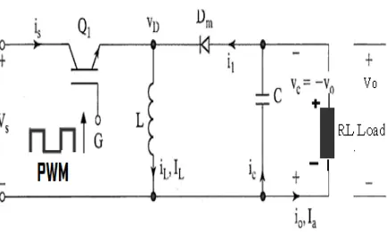
[image:15.612.115.549.366.627.2]A buck-boost converter provides an output voltage that may be less than or greater than the input voltage hence the name „‟buck-boost‟‟; the output voltage polarity is opposite to that of the input voltage. This converter is also known as an inverting regulator. The circuit arrangement of a buck-boost convertor is shown in figure 2. 1:
7
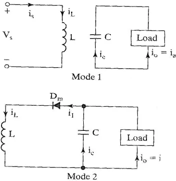
Figure 2.2: equivalent circuits of Buck boost converter
8
9
The rate of change of inductor current is a constant, indicating a linearly increasing inductor current. The preceding equation can be expressed as
∆𝑖𝐿
∆𝑡 =
∆𝑖𝐿
𝐷𝑇 =
𝑉𝑠
𝐿 (2.1)
Solving for ∆𝑖𝐿 when the switch is closed
∆𝑖𝐿 𝑐𝑙𝑜𝑠𝑒𝑑 = 𝑉𝑠𝐷𝑇
𝐿 (2.2)
Analysis for the switch open.When the switch is open; the current in the inductor cannot change instantly, resulting in a forward-biased diode and current into the resistor and capacitor. In this condition, the voltage across the inductor is
𝑣𝐿 = 𝑉𝑂 = 𝐿 𝑑𝑖𝐿
𝑑𝑡 (2.3) 𝑑𝑖𝐿
𝑑𝑡 =
𝑉𝑂
𝐿 (2.3)
Again the rate of change of inductor current is constant, and the change in current is
∆𝑖𝐿
∆𝑡 =
∆𝑖𝐿
1−𝐷 𝑇 = 𝑉0
𝐿 (2.4)
Solving for ∆𝑖𝐿,
∆𝑖𝐿 𝑜𝑝𝑒𝑛 =
𝑉0 1−𝐷 𝑇
𝐿 (2.5)
For steady-state operation, the net change in inductor current must be zero over one period using Eqs.2.2 and 2.5,
∆𝑖𝐿 𝑐𝑙𝑜𝑠𝑒𝑑 + ∆𝑖𝐿 𝑜𝑝𝑒𝑛 = 0
𝑉𝑠𝐷𝑇
𝐿 +
𝑉𝑂 1−𝐷 𝑇
𝐿 = 0 (2.6)
Solving for𝑉𝑂,
𝑉𝑂= −𝑉𝑠 𝐷
10
Equation 2.7 shows the output voltage has opposite polarity form the source voltage. Output magnitude of the buck boost converter can be less than the source greater than the source, depending on the duty ratio of the switch. If D > 0.5, the output is larger than the input, and if D < 0.5, output is smaller than the input.
Note that the source is never connected directly to the load in the buck boost converter. Energy is stored in the inductor when the switch is closed and transferred to the load when switch is open. Hence, the buck boost converter is also referred to as an indirect converter.
Power absorbed by the load must be the same as that supplied by the source,
where
𝑃𝑂 = 𝑃𝑂2
𝑅 (2.8)
𝑃𝑠 = 𝑉𝑠𝐼𝑆 (2.9)
𝑉𝑂2
𝑅 = 𝑉𝑆𝐼𝑆 (2.10)
Average source current is related to average inductor current by
𝐼𝑆 = 𝐼𝐿𝐷
Resulting in
𝑉𝑂2
𝑅 = 𝑉𝑆𝐼𝐿𝐷 (2.11)
Substituting for 𝑉𝑂 using Eqe 2.7 and solving for
𝐼𝐿 = 𝑉𝑂2
𝑉𝑆𝐷𝑅 =
𝑃𝑂
𝑉𝑆𝐷 =
𝑉𝑆𝐷
𝑅 1−𝐷 2 (2.12)
Maximum and minimum inductor current is determined using Eqe 2.2 and 2.12
𝐼𝑚𝑎𝑥 = 𝐼𝐿+ ∆𝑖𝑙
2 =
𝑉𝑆𝐷
𝑅 1−𝐷 2+
𝑉𝑆𝐷𝑇
2𝐿 (2.13)
𝐼𝑚𝑖𝑛 = 𝐼𝐿− ∆𝑖𝑙
2 =
𝑉𝑆𝐷
𝑅 1−𝐷 2+
𝑉𝑆𝐷𝑇
11
For continuous current, the inductor current must remain positive. To determine the boundary between continuous and discontinuous current 𝐼𝑚𝑖𝑛 is set to zero in Eqe 2.14,
𝐿𝐹 𝑚𝑖𝑛 =
1−𝐷 2𝑅
2 (2.15)
Or
𝐿𝑚𝑖𝑛 = 1−𝐷
2𝑅
2𝑓 (2.16)
When F is switching frequency in hertz
Output voltage ripple
The output voltage ripple for the buck boost converter is computed from the capacitor current waveform
∆𝑄 = 𝑉𝑂
𝑅 𝐷𝑇 = 𝐶∆𝑉𝑂 (2.17)
Solving for ∆𝑉𝑂,
𝑉𝑂= 𝑉𝑂𝐷𝑇
𝑅𝐶 =
𝑉𝑂𝐷
𝑅𝐶𝐹 (2.18)
∆𝑉𝑂
𝑉𝑂 =
𝐷
𝑅𝐶𝐹 (2.19)
2.4 Fuzzy Logic Controller
Fuzzy Logic Controller (FLC) is constitutes a way of converting linguistic control strategy into an automatic by generating a rule base which controls the behaviour of the system. Fuzzy control is control method based on fuzzy logic. Fuzzy provides a
12
information. It suitable for applications such as the speed control of dc motor which is has non linearities. (Siler, W. and Ying, H, 1989)
FLC have some advantages compared to other classical controller such as simplicity of control, low cost and the possibility to design without knowing the exact mathematical model of the process. Fuzzy logic incorporates an alternative way of thinking which allows modelling complex systems using higher level of abstraction originating from the knowledge and experience. Fuzzy logic can be described simply as computing words rather than numbers” or “control with sentence rather than equations.” (Siler, W. and Ying, H, 1989)
The applications of fuzzy logic are usually for household appliance such as washing machine and rice cooker. Fuzzy also been used in industrial process such as cement kilns, underground trains and robots.
2.5 Structure of Fuzzy Logic
Structure of a fuzzy logic controller consists of: input, fuzzification, Rule base, Defuzzification, output. There are specific components characteristic of a fuzzy controller to support a design procedure. Figure 2.4.Shows the controller between the input and output. (Jan Jantzen 1998)
13
2.5.1 Input
The inputs are most often hard or crisp measurement from some measuring equipment is converted into fuzzy values for each input fuzzy set with the fuzzification block. (Jan Jantzen 1998)
2.5.2 Fuzzification
The first block inside the controller is fuzzification which converts each piece of input data to degrees of membership by a lookup in one or several membership
functions. The fuzzification block matches the input data with the conditions of the rules to determine. There is degree of membership for each linguistic term that applies to the input variable. (Jan Jantzen 1998)
2.5.3 Rule Base
The collection of rules is called a rule base. The rules are in “If Then” format and formally the If side is called the conditions and the Then side is called the conclusion. The computer is able to execute the rules and compute a control signal depending on the measured inputs error (e) and change in error.(dE). In a rule based controller the control strategy is stored in a more or less natural language. A rule base controller is easy to understand and easy to maintain for a non- specialist end user and an equivalent controller could be implemented using conventional techniques. (Jan Jantzen 1998)
2.5.4 Defuzzification
Defuzzification is when all the actions that have been activated are combined and
14
The output levels are depending on the rules that the systems have and the positions depending on the non-linearities existing to the systems. To achieve the result, develop the control curve of the system representing the I/O relation of the systems and based on the information; define the output degree of the membership function with the aim to minimize the effect of the non-linearity (Jan Jantzen 1998)
2.5.5 Output
The output is output gain that can be tuned and also become as an integrator .The output crisp value can be calculated by the centre of gravity or the weighted average [7]
2.6 eZdspTM F2808 board
The eZdspTM F2808 is a stand-alone card--allowing evaluators to examine the
TMS320F2808 digital signal processor (DSP) to determine if it meets their application requirements. Furthermore, the module is an excellent platform to develop and run software for the TMS320F2808 processor.
The eZdspTM F2808 is shipped with a TMS320F2808 DSP. The eZdspTM F2808 allows full speed verification of F2808 code. Expansion connectors are provided for any necessary evaluation circuitry not provided on the as shipped configuration.
15
Figure: 2.5: eZdspTM F2808 board
2.6.1 Key Features of the eZdspTM F2808
The eZdspTM F2808 has the following features: • TMS320F2808 Digital Signal Processor • 100 MIPS operating speed
• 18K words on-chip zero wait state SARAM • 64K words on-chip Flash memory
• 256K bits serial I2C EEPROM memory • 20 MHz. clock
• Expansion Connectors (analog, I/O) • Onboard IEEE 1149.1 JTAG Controller
• 5-volt only operation with supplied AC adapter • TI F28xx Code Composer Studio tools driver • On board USB JTAG emulation connector • 2 SCI UART channels
CHAPTER 3
METHODOLOGY
3.1 Introduction
This chapter discusses the software and hardware development and implementation of the project and procedures that are being used to develop the project including the equipment, tools and processes used in the software and hardware development and implementation of the project. The mythology process utilizes both software simulation and hardware construction. It is virtual to simulate the system by using software to get the theoretical result before hardware designation can be made. The selection of component for the hardware is also important in order to reduce cost, increase the system efficiency and increase reliability of the circuit.
17
NO YES
NO YES
NO
YES
NO YES
Figure 3.1: Flowchart of project Start
Research and observation of the project
Study all the information
Understand?
Designing DC-DC Buck boost converter circuit using MATLAB Simulink software
Simulation Success?
Designing of fuzzy logic controller using MATLAB toolbox software
Develop PWM switching and fuzzy logic controller using MATLAB 2007a software
Compilation Success?
Download into eZdspTM F2808 board
Hardware Function?
Result and analysis
18
The Comprehensive planning of this project is shown in Figure 3.1. The flowchart of this project was begin by doing some research and observation based on the previous research especially the information related with the applications of PWM generation and Fuzzy logic controller technique. The next stage is to do the simulation of DC-DC Buck boost converter by using Matlab Simulink software. After doing this simulation circuit part, the next stage is the programming of Fuzzy logic controller using Matlab toolbox. Finally, generated code of PWM switching pulses and controller using real time workshop on Matlab Simulink software to download into eZdspTM F2808 board and connected with the gate driver circuit and buck boost converter circuit. The output of converter is analyzed in term of number of pulse signals and output voltage.
3.2 Proposed design
In order to control the DC output voltage of buck boost converter and to ensure good variable output voltage the fuzzy logic controller for closed loop control of DC -DC Buck boost convertor proposed in this project.
Figure 3.2.Shows the block diagram of the proposed system. The system consists of dc-dc buck boost converter to maintain dc voltage. A sensor is used to sense the output voltage and which is used for voltage feedback. A digital signal processor is employed to generate Fuzzy logic controller and PWM signal to switch the dc-dc buck boost converter.
19
In the proposed system two input fuzzy controllers are used. The error and change in error are given as inputs to the fuzzy logic controller. The output of the fuzzy controller is denoted as duty cycle.
20
3.2 Fuzzy logic controller for proposed system
In Fuzzy logic system the linguistic variables are used instead of numerical variables. The process of converting a numerical variable (real number or crisp variables) in to a linguistic variable (fuzzy number or fuzzy variable) is called fuzzification.
In this work, the dc voltage converter variables are voltage. The output voltage is controlled by Fuzzy logic controller. The error e(k) and change in error ∆e(k) is given as input to the Fuzzy logic controller. The error is found by comparing the actual voltage Vo(k) with reference voltage Vrf(k). From the error e(k) and previous error E
previous(k) the change in error is calculated and then it is normalized, in order to use the same fuzzy logic controlerfor different reference voltage. Then the error and Change in error are fuzzified (Adel E. El-kholy and A. M. Dabroom,2002) given in equations (3.1) and (3.2)
e(k) = Vrf(k) - Vo(k) (3.1)
∆e(k) = e(k) - E previous(k) (3.2)
21
Figure 3.3: Error (input)
22
The control rules that relate the fuzzy output to the fuzzy inputs are derived from general knowledge of the system behavior, also the perception and experience.
However, some of the control rules are developed using “trial and error” method. (T.Gupta & R.Boudreax, 1997)
The general rule can be written as
The rule table for the designed fuzzy controller is given in the Table 3.1 (N Senthil Kumar, 2007). The element in the first row and first column means that If error is NB, and change in error is NB then output is NB.
23
The reverse process of fuzzification is called defuzzification. The linguistic variables are converted in to a numerical variable. As the weighted sum method is considered to be the best well-known defuzzification method, it is utilized in the present model.
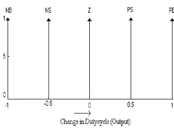
The defuzzified output is the duty cycle dc(k). The change in duty cycle ∆dc(k)can be obtained by adding the pervious duty cycle pdc(k) with the duty cycle dc(k) which is given in equation . Figure 3.5: Change in Duty cycle (output)
∆𝑑𝑐 𝑘 = 𝑑𝑐(𝑘) + 𝑝𝑑𝑐 𝑘 (3.3)
[image:32.612.122.465.337.590.2]24
3.3 Fuzzy Logic Toolbox
There are five primary graphical user interface (GUI) tools for building, editing and observing fuzzy inference systems in the toolbox:-
-Fuzzy Inference System (FIS) editor - Membership Function editor
-Rule Editor -Rule Viewer -Surface Viewer
65
REFERENCES
Adel E. El-kholy and A. M. Dabroom, (2006): Adaptive Fuzzy Logic Controllers for DC Drives: A Survey of the State of the art, Journal of Electrical Systems, pp. 116-145.
Jabri Majed, Chouiref Houda, Jerbi Houssem, Benhadj Braiek and Naceur, (2008): Fuzzy logic parameter estimation of an electrical system Systems, Signals and Devices,
IEEE SSD, 5th International Multi-Conference, pp.
Jan Jantzen, (1998 ): Design Of Fuzzy ControllersTechnical University of Denmark, Department of Automation, Bldg 326, DK-2800 Lyngby, DENMARK. Tech. report no 98-E 864 (design).Bimal K.Bose (2003): Modern Power Electronics and AC Drives. Pearson Education.
J.-S. Roger Jang, (1997): Fuzzy Logic Toolbox User’s Guide COPYRIGHT 1984 - 1997 by The MathWorks, Inc. All Rights Reserved Cheng- Yuan Liou and Yen-Ting Kuo.
LIN P.Z., LIN C.M., HSU C.F., LEE T.T, (2006): Type-2 fuzzy controller design using a sliding-model approach for application to DC-DC converters’, IEE Proc. Electr.
Power, 152, (6), pp. 1482–1488.
66
Muhammad H. Rashid, (1993): Power electronics circuits, devices and applications, 2d edition.
Ozdemir, E.; Ural, A.; Abut, N.; Karakas, E.; Olcer, E.; Karagoz, B.; (1997): Design of fuzzy logic controller for DC-DC converter fed traction motor Drives Intelligent
Control, Proceedings of the 1997 IEEE International Symposium.
Rashid, M. H. (Ed), (2007): Power Electronics Handbook: Devices, Circuits, and Applications. Florida: Elsevier Inc.
S. Arulselvi , G. Wma, L. Hem chandiran andV. Saminath4(2005): Design and Controller (SFLC) for the Voltage Control of Resonant Converter Implementation of
Simple Fuzzy Logic Department of Electrical and Electronic Engineering College of
Engineering, Anna University Guindy, Chennai, India.
Siler,W. and Ying, H. (1989). Fuzzy control theory: The linear case, fuzzy sets and system.
SO W.C., TSE C.K., LEE Y.S, (1996): Development of a fuzzy logic controller for DC/DC converters: design, computer simulation, and experimental evaluation’, IEEE
Trans. Power Electron., 11, (1), pp. 24–32.
Texas Instruments (2007): TMS320C28x™ DSP Workshop.
T.Gupta & R.Boudreax, (1997): Implementation of a Fuzzy Controller for DC-DC Converters Using an Inexpensive 8-Bit micro controller, IEEE Trans. on Industrial