Modeling and Optimization of Capacitive Converter for
Energy Scavenging System
Jinxin Huang, Nannan Gao, Hongbo Li State Grid of China Technology College, Jinan, China
Email: [email protected] Received March, 2013
ABSTRACT
A new converter with spherical cap for energy scavenging is proposed. Based on the method of separated variables within the torrid coordinate system, a corresponding analytical model for spherical cap converter is further established so as to obtain the analytic expressions of the topology capacitance and the output voltage. The concept of energy in-crement factor is specifically defined to denote the improvement of energy storage efficiency. With regard to spherical cap converters of different dimensions, the measured values of energy increment factor coincide well with the theoreti-cal equivalents, indicating an effective verification of the proposed analytitheoreti-cal model for the spheritheoreti-cal cap converter to-pology.
Keywords: Energy Scavenging System; Capacitive Converter; Spherical Cap Topology; Energy Increment Factor
1. Introduction
With the development of smart grid and wireless sensor technology, it’s necessary to study energy scavenging technology [1-5] to collect the energy in the surrounding environment (such as solar energy, vibration energy, thermal energy and electromagnetic energy) and convert them into electricity for powering sensor nodes. There contains much electromagnetic energy in high voltage substations and it provides a basis for energy scavenging system based on electric field energy. Under the specific environmental conditions in substations, the system has some unique advantages compared with other ones.
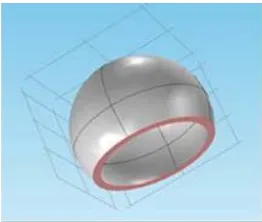
At present, a British research team has conducted a preliminary study of it and this provides a fundament for reference [6]. A traditional flat-plate capacitive converter is adopted in their researches. The electric field is very complex in the substations, so the electric field sur-rounding the capacitive converter maybe come from dif-ferent directions. For the traditional flat-plate one, it has good effect only at the vertical direction. In order to col-lect the ecol-lectric field energy preferably from different directions, a new capacitive topology with spherical cap is proposed, as Figure 1 shows. This new topology is not
only more suitable for collecting all directions of the electric field, but also conducive to offer electromagnetic shielding for conditioning unit, and avoid marginal dis-charge.
It can increase energy storage capacity of the converter by optimizing the parameters. This depends on the
accu-rate modeling and analysis of the converter. The opening of converter destroys the spherical symmetry, so it be-comes difficult to solve the charge and electric potential distribution and capacitance expressions directly in the Cartesian coordinate system. Calculation model of the converter in the torrid coordinate system [7] is estab-lished to get analytic formulas of non-complete spherical cap by using variables separation and Laplace equation.
2. Mathematical Modeling of Capacitive
Converter
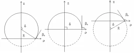
According to different sizes of spherical topology, it can be divided into three cases: more halfsphere, halfsphere, and less half sphere which corresponding δ and 0 are
different, as shown in Figure 2. Torrid coordinate system
[image:1.595.357.488.609.720.2]is a generalized orthogonal curvilinear coordinates, the three parameters are (, , ) and they have a relation with Cartesian coordinates (x, y, z) as equation (1) shows.
Figure 2. Analytical model of spherical cap converter in torrid coordinate system.
sh cos ch cos sh sin ch cos sin ch cos a x a y a z (1)
where, 0≤<∞,0≤≤2π,0≤<2π, a is a parameter in torrid coordinate and denotes opening radius of the spherical cap.
Assume that the radius is R, the electric potential is u. External space of the converter meets the Laplace equa-tion . In torrid coordinate system,is rotational symmetry and there is no relation between u and . Omit partial differential item on and make Laplace expansion as (2).
2u 0
sh sh 0
ch cos ch cos
u u
(2)
Use separation of variables to represent ( , , )u 2ch2ch cosX( ) ( ) Y and take it into equation (2), so equation (3) and (4) can be obtained, where b is the coefficient.
exp
Y ib (3)
2
1 d sh d 1 0
sh d d 4
X b X
(4) Equation (4) is the Legendre equation, its solution is the Legendre function as (5) shows.
12
12
1 1
2 2
ch , ch , is real number ~
ch , ch , is imaginary number b
i i
P Q b
X
P Q b
(5) Because the potential function is bounded, the equa-tion (4) remains bounded and just take the first Legendre equation of (5) into account, where 1
2 b
1
0
2
2ch 2ch
ch sh ch d
i
u
A B P
(6) The spherical cap meets β=β0 and point coordinatesoutside the spherical cap meet β0≤β≤β+2π, and
expres-sion (6) can be adapted to (7).
1 0 2 0
0
1 2
2ch 2ch
( )sh ( ) ( )sh (2 )
sh(2 ) ch d i u C C P
(7)According to the boundary conditions u 0
0 2 0
u u and method of undetermined coefficients, C1(τ) and C2(τ) can be established by expression (8).
0 1 2 0
ch( )
( ) ( )
ch( )
C C u
(8) Then with substitution Equation (7) is rewritten as
0 0 0 1 2 0 2 2ch 2chch( ) ch( )
ch d
ch (2 ) i
u u P
(9)Use integral formula of Legendre
1 0
2
cos 2
ch ch d
π 2ch 2ch
i P
(10)Finally, the electric potential distribution formula (11) can be got by using Fourier integral transformation.
0 0 0 0 0 ch cos 12 ch cos 2
2 cos 2 2 arctan ch cos ch cos
2 ch cos 2
2 cos 2 arctan
ch cos 2 u
u
(11)
Based on the space distribution of electric potential, the capacitance of the converter can also be deduced by the following steps.
b i P ch
, . To get the general expression of potential function u as (6) shows, take the solutions of equation (3) and (4) into it, denoting the coefficient functions of τ by A(τ) and B(τ).
0 0 0 0 0 2 1 internal surface 1 external surface E n u e n h u e n h , ,
(12)0 0 0
in 0
0 0
0 sin 2ch 2cos
2
2 cos 2
2cos arc cot
2 cos u ch (13) 0 0 ex in sin 0
u
(14)
where, in and ex is the density of internal and external
surface charge respectively.
The charge on the internal surface of the converter qin
is calculated as (15), the same method can be used to calculate qex, finally the total charge qall can be completed
by (16).
0 0 in in 0 0
0
d 2 1 tan
2 2 sin
q s u a
(15)0 all in ex 0 0
0
4 1
sin
q q q u a
n (16)Here, δ=π-β0 and sinβ0=sinδ=a/R, then equation (16) is
rewritten as
all 4 0 0 si
q u R (17) The capacitance of converter is got.
all sph 0 0 4 sin q C Ru
(18)
The capacitance formula (19) with parameters of R and a is rewritten by using the coordinate transformation, corresponding to the three cases in Figure 2.
0 sph 0 0 4 arcsin 2 4 1 2 2 4 arcsin 2 a a R R R C R a a R R R (19)
3. Optimization of Capacitive Converter
In order to compare the effect of energy harvesting, de-fine the incremental coefficient n which is the ratio of the two capacitances within the same volume.sph flat
C n
C
(20)
As a result, optimization of the converter can be transformed into the optimization of incremental coeffi-cient n, described as equation (21).
sph flat sph flat max . . C n C s t V V
V V (21)
Its goal is to maximize the increment factor n, while the constraint is limited by its volume V. Bring the ca-pacitance of traditional flat-plate converter and the spherical cap one into formula (20) then equation (22) can be got.
2 4 +π-arcsin 1 1
π
( )
2 2 4 +arcsin 1 1
π R
2
( )
2
a a a
R R R
n a a a
R R a R (22)
where, >90°, V is limited by a cylinder with radius R and height R+a, while <90°, V is limited by a cylinder with radius a and height R-a.
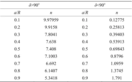
It is clear that incremental coefficient n is the function of a/R, and it satisfies 0<a/R<1. As a reference, Table 1
[image:3.595.307.539.592.736.2]shows the calculated incremental coefficient n for dif-ferent a/R, which reflects changes of opening radius a to the improvement of efficiency.
Table 1. Incremental factor for different sizes of converter.
δ>90o δ<90o a/R n a/R n
0.1 9.97959 0.1 0.12775
0.2 9.9158 0.2 0.25813
0.3 7.8041 0.3 0.39403
0.4 7.638 0.4 0.53913
0.5 7.408 0.5 0.69843
0.6 7.1003 0.6 0.8796
0.7 6.692 0.7 1.0959
Table 1 shows that, when >90°, the smaller is the
opening radius a, the more close to a ball, the greater is the capacitance, and the more energy it stores. Limited by the bottom plate grounded, the spherical cap can not be infinitely close to a ball. When <90°, the smaller is the opening radius a, the less energy it can store. When a/R is 0.7, the increment factor n is 1.0959, it begins to increase the stored energy. Therefore, a/R at least se-lected in 0.7 can improve the efficiency of energy storage (equivalent to the flat-plate converter). In particular, when =90°, the incremental coefficient n is 3.27.
4. Experiment about Incremental Coefficient
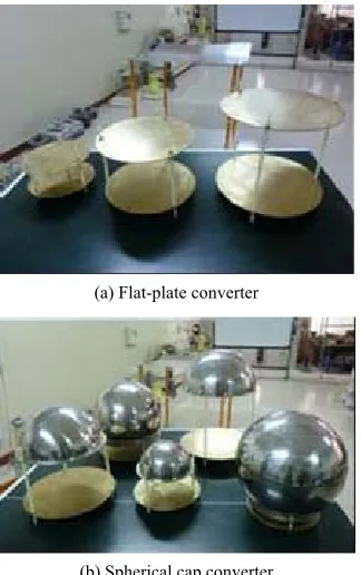
To verify the validity of the analytical model, an experi-ment about the increexperi-ment factor n is done. It can get measured capacitance for different sizes of flat-plate converter and the spherical cap one by using high preci-sion LCR meter named Quadtech1869 M. Figure 3shows different samples of the converter with different dimensions. The height of two plates can be regulated by insulating pillars to meet the limitations of volume. Measurements and theoretical values of incremental co-efficient n are shown in Table 2.
The results in Table 2 show that the measured values
n agree well with the theoretical ones. For > 90°, when a/R is 0.5, the error of measured values n with the theoretical ones is small; but when a/R increases to 0.6, the measured values is smaller, because with a/R in-creases,
(a) Flat-plate converter
[image:4.595.93.255.449.707.2](b) Spherical cap converter
Figure 3. Different samples of the converter with different dimensions.
Table 2. Theoretical value and measured value of incre-mental factor.
Types a/R Theoretical value n Measured value n
0.5 7.408 7.013 7
δ>90o
0.6 7.100 3 5.947 2
0.6 0.879 6 0.774 5
δ<90o
0.8 1.374 5 1.462 8
δ=90o 1.0 3.273 89 3.156 29 the spherical cap is more close to a ball, the electrostatic shielding becomes stronger. For < 90°, only when a/R is greater than 0.7, it can improve the effect of energy storage. In particular, for = 90°the measured value is 3.156, and the capacitance increases three times compared with the flat-plate converter in the same volume. The experiment shows that the analytical model of spherical cap converter in the torrid coordinate system is valid.
5. Conclusions
This paper focuses on capacitive converter of energy scavenging system based on electric field energy to carry out research on theoretical analysis, modeling, optimiza-tion, and experiments. Analytic forms of the electric po-tential and capacitance is deduced based on the separated variables in the torrid coordinate system. Incremental factor about energy storage is proposed to compare the effect of energy harvesting. At last, the proposed model-ing and optimization methodology are verified by testmodel-ing experiments.
REFERENCES
[1] Y. X. Yu and W. P. Luan, “Smart Grid and Its Imple-mentations,” Proceedings of the CSEE, Vol. 29, No. 34, 2009, pp. 1-8.
[2] A. P. Joseph and S. Thad, “Energy Scavenging for Mo-bile and Wireless Electronics”, IEEE Transactions on Pervasive Computing, Vol. 4, No. 1, 2005, pp. 18-27.
doi:10.1109/MPRV.2005.9
[3] D. S. Lee, “Wireless and Powerless Sensing Node System Developed for Monitoring Motors,” Sensors, Vol. 8, No. 8, 2008, pp. 5005-5022.doi:10.3390/s8085005
[4] Y. G. Sun, “Study on Structure Vibration Wireless Sensor Based on Solar Cell,” Noise and Vibration Control, No. 4, 2007, pp. 132-133.
[5] S. S. Nathan and A. P. Joseph, “Energy Scavenging with Shoe-mounted Piezoelectrics,” IEEE Micro, Vol. 21, No. 3, 2001, pp. 30-42.
Montreal, Canada, May 31-June 3, 2009, pp. 36-40 [7] X. Li, “Computation of the Eccentric Spherical
Ca-pacitor's Capacitance,” Journal of Capital Normal