© 2017, IRJET | Impact Factor value: 5.181 | ISO 9001:2008 Certified Journal | Page 1754
AN EXPERIMENTAL INVESTIGATION AND OPTIMIZATION OF PROCESS
PARAMETERS OF ROLLER BURNISHING
Lad S.P.
1, Shirke P.R.
2, Lohar A.B.
3, Kulye P.D.
4,Khandekar S.B.
51
Student of B.E., Mechanical Engineering, Rajendra Mane College of Engineering and Technology, Devrukh,
Maharashtra, India.
2
Student of B.E., Mechanical Engineering, Rajendra Mane College of Engineering and Technology, Devrukh,
Maharashtra, India.
3
Student of B.E., Mechanical Engineering, Rajendra Mane College of Engineering and Technology, Devrukh,
Maharashtra, India.
4
Student of B.E., Mechanical Engineering, Rajendra Mane College of Engineering and Technology, Devrukh,
Maharashtra, India.
5
Assistant Professor, Mechanical Engineering, Rajendra Mane College of Engineering and Technology, Devrukh,
Maharashtra, India.
---***---Abstract -
Roller burnishing is the process of surfacemodification in which, a hard roller is pressed against a rotating cylindrical work piece and parallel to axis of the work piece. The main objective of this study is to enhance the surface roughness and surface hardness of the EN-8 specimen using the roller burnishing process. This research work involves experimental investigation of roller burnishing process with regard to process parameters such as speed, feed, and number of passes. The EN-8 steel work piece material and H.S.S. single roller burnishing tool is used for carrying out this research work. The process parameters considered are speed (1000 R.P.M., 1200 R.P.M., 1400 R.P.M.), feed (0.08mm/rev, 0.1mm/rev, 0.12 mm/rev) and number of passes(2, 3, 4). Effect of these parameters on response variables such as surface roughness and surface hardness is characterized by DOE. Results shows that dominating factor affecting surface roughness is speed and that of for surface hardness is number of passes. From this study, it is observed that the better surface finish up to 0.26 micron is obtained and also hardness is improved by 20% and increased up to 254 BHN.
Key Words: Roller burnishing, Surface roughness, Surface
hardness, DOE, Burnishing speed, feed and number of passes.
1. INTRODUCTION
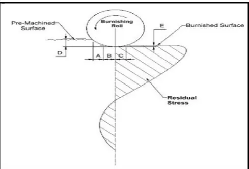
Burnishing process is use for the surface modification which gives a very fine surface finish by the planetary rotation of a roller over a cylindrical surface. The tool may consist of one or more ball or roller. There is no removal of material from the work pieces. All machined or other processed metal surfaces consist of a series of peaks and valleys which constitute the surface irregularities. Due to the applied burnishing force peaks of the roughness flows into the valleys. This reduces the height of the peaks and depth of the valleys, thereby reducing the surface roughness.
Burnishing process can be done by two ways, Roller burnishing process and Ball burnishing process. The ball material is hardened alloy steel, carbide, diamond, etc. The roller material is hardened alloy steel, carbide, etc. In this paper, experiments with roller burnishing tool are presented. The schematic diagram shows the operating principle of roller burnishing process.
Fig -1: Schematic diagram of roller burnishing process
[image:1.595.310.555.418.584.2]© 2017, IRJET | Impact Factor value: 5.181 | ISO 9001:2008 Certified Journal | Page 1755
2. LITERATURE REVIEW
2.1MalleswaraRao J. N. ,ChennaKesava Reddy A. , Rama Rao P. V. (2011) [1] found that the surface hardness of mild steel specimens increases with increase in the burnishing force up to 42 kgf. Further increase of burnishing force results in the decrease of surface hardness on mild steel specimens. The maximum surface hardness obtained is70 HRB. Maximum reduction in surface roughness was observed in first five passes on mild steel by Roller Burnishing operation.
2.2 P. S. Kamble and V. S. Jadhav (2012) [2] found that theroller burnishing produce superior finish. Ra value observed is finest up to 0.13 micron. Before burnishing micro hardness found 377Hv and after burnishing it increases up to 528Hv.Many researchers carried out experiments on external work piece by single roller burnishing tool. From this study it was observed that roller burnishing also gives better result in drilled hole.
2.3 Jignesh R. Patel, Prof. S. M. Patel May(2014) [3] found that in this process both force and speed were affected more as compared to feed.
Burnishing speed - In this parameter when speed kept low surface roughness was low and surface hardness was high. Burnishing force - At high force in both parameter surface roughness decreased and surface hardness increased and at low force surface roughness was increased and surface hardness was Decreased.
Burnishing feed - With increase in feed in both parameter surface roughness was increased where as surface hardness was decreased.
2.4Mr.Ashwin Joshi, Dr. R. N. Patil (2015) [4] found that in this study, Master Burnishing Tool consisting of single roller having material ‘D3 too steel’ is used. The present work has lead to the following conclusions.
1. It has been established that Taguchi analysis was an effective optimization technique.
2. Mathematical model for surface finish, burnishing response is identified by Taguchi method considering speed, feed, and number of passes.
3. The established model is useful in predicting the response which by selecting proper input parameters that were used in this research work before performing the burnishing process.
3. ROLLER BURNISHING TOOL
There are several type of tools depends on the application of use. Some of them are single roller burnishing tools that are consist of body equipped with a tool shank, a spring assembly that allows the roller head to move with no play and very low friction. Single roller tools are design to machine a wide variety of irregular surface. These types of
tools can be used for burnishing external cylindrical surfaces of different diameter dimensions.
Tool Material and Design
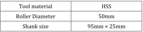
Roller burnishing tools included a rotating system of hardened, tapered roller which is pressed against work surface. When a tool engages the work piece a hardened mandrel inversely to the taper of the rolls, forces them against the surface of the work piece. Roller burnishing tool used for conducting this research work is shown in following fig. 2
[image:2.595.308.554.456.512.2]Fig -2: Single Roller Burnishing Tool
Table -1: Tool Specifications
Tool material HSS
Roller Diameter 50mm
Shank size 95mm × 25mm
4. DESIGN OF EXPERIMENTS (DOE)
Design of experiment (DOE) involve designing a set of minimum experiments, In which all the factors considered are varied systematically. After analyzing the results of these experiments, optimal conditions can be identify. The levels that should be taken, how to combine them, and how many experiments should be run are subjected to important in DOE. To make comparison of the performance minimum two levels are required and they determine the effect. DOE with Taguchi method helps to improve consistency of performance and reduces the time without doing the full factorial experiments.[6]
© 2017, IRJET | Impact Factor value: 5.181 | ISO 9001:2008 Certified Journal | Page 1756
5. EXPERIMENTAL SETUP AND PROCEDURE
Burnishing experiments are conducted on EN8 work piece, which is ductile and Available commercially in the form of round bars. First, The program for turning the work piece was feed in the CNC lathe and then work piece is held in 3 jaw chuck of CNC lathe and facing operation is completed on both sides. Then, the work piece is held in between centres of CNC lathe and it is driven through the lathe dog. A carbide Single point cutting tool is fixed in the tool post of the lathe and work piece is turned to have steps.
Fig -3: Experimental setup of roller burnishing operation on CNC lathe.
In the present work, roller having outside diameter of 50 mm and 25 mm width is used for burnishing. The roller burnishing tool assembly is kept in the tool holder and it is held rigidly by two bolts. This experimental work conducted on CNC lathe machine. The main advantage of using such a machine is its flexibility. It enables the machining and burnishing operation to be accomplished easily in as sequential order. Any change in burnishing condition such as speed feed, and number of passes can be easily adjusted. Figure 3 shows the experimental set-up of machining.
Minitab17software is used for the set up Taguchi orthogonal array. This software is also used to calculate signal to noise ratio(S/N ratio) which is consider for the smaller is better type of response for surface finish and larger is better type of response for surface hardness.
Response Parameters
This project is carried out by considering the surface finish and surface hardness as response parameters. The main aim of this work is to optimize the process parameters of roller burnishing tool to have a better surface finish and surface hardness.
[image:3.595.305.560.143.241.2]Process Parameters and their levels for Roller Burnishing Processes:
Table -2: Process Parameters
Parameters Level 1 Level 2 Level 3
Speed(RPM) 1000 1200 1400
Feed(mm/rev) 0.08 0.1 0.12
Number of
Passes 2 3 4
6. RESULT AND DISCUSSION
6.1 Study of surface roughness
[image:3.595.36.283.242.395.2]From the study work, we come to know that there is significant change in surface roughness due to the variation in process parameters like spindle speed, feed and number of passes. The surface finish of normally turned specimen is 0.98µm and after burnishing the surface finishing increases up to the 0.26µm.The S/N ratio for smaller is better type of response is used and recorded for surface finish.
Table -3:L9 orthogonal array and observation
Expt.
No. Speed (rpm) (mm/rev) Feed passes No. of Surface finish ratio S/N
1 1000 0.08 2 0.31 10.033
2 1000 0.1 3 0.26 11.700
3 1000 0.12 4 0.27 11.372
4 1200 0.08 3 0.30 10.457
5 1200 0.1 4 0.33 9.4991
6 1200 0.12 2 0.37 8.5194
7 1400 0.08 4 0.28 10.903
8 1400 0.1 2 0.37 8.6360
9 1400 0.12 3 0.34 9.3704
Table -4: Response table of S/N ratio for smaller is better
Level Speed Feed No. of passes
1 11.036 10.465 9.063
2 9.492 9.945 10.510
3 9.636 9.754 10.592
Delta 1.544 0.711 1.529
[image:3.595.306.564.425.634.2]© 2017, IRJET | Impact Factor value: 5.181 | ISO 9001:2008 Certified Journal | Page 1757 From above response table it is seen that the speed is
effectively responsible for the better surface finish. It is clear that, speed is first process parameter to be considered for the single roller burnishing process for surface finish.
Fig -4: Means of S/N ratio vs speed, feed, no. of passes
6.2 Study of surface Hardness
[image:4.595.304.559.120.235.2]Burnishing process also give the variation in surface hardness of specimen because of variation in process parameters. The Brinell hardness test is carried out to find the surface hardness. The surface hardness is increased up to 20% after burnishing process. The surface hardness of normally turned specimen is 218 BHN. The S/N ratio for larger is better type of response is used and recorded for surface hardness.
Table -5: L9 orthogonal array and observation
Expt.
No. Speed (rpm) (mm/rev) Feed passes No. of BHN ratio S/N
1 1000 0.08 2 225 47.0437
2 1000 0.1 3 238 47.5315
3 1000 0.12 4 242 47.6763
4 1200 0.08 3 223 46.9661
5 1200 0.1 4 241 47.6403
6 1200 0.12 2 240 47.6042
7 1400 0.08 4 254 48.0967
8 1400 0.1 2 238 47.5315
[image:4.595.37.283.159.353.2]9 1400 0.12 3 236 47.4582
Table -6: Response table of S/N ratio for larger is better
Level Speed Feed passes No. of
1 47.42 47.37 47.39
2 47.40 47.57 47.32
3 47.70 47.58 47.80
Delta 0.29 0.21 0.49
Rank 2 3 1
From above response table it is seen that see that the number of passes is effectively responsible for the better surface hardness. It shows that number of passes is first process parameter to be considered for the single roller burnishing process for surface hardness.
Fig -5: Means of S/N ratio Vs speed, feed, no. of passes
7. CONCLUSIONS
From the above study we come to know that burnishing process is efficiently effective for improvement of surface finish and surface hardness of EN8 steel material. Lots of research work is carried out on the external work surface by using single roller carbide burnishing tool. From this study it is observed that roller burnishing with HSS roller burnishing tool also gives better surface finish and improves surface hardness.
The superior surface finish is obtained and it is observed up to 0.26 micron. Also surface hardness is improved by 20% and increased up to 254 BHN.
[image:4.595.309.557.317.528.2] [image:4.595.30.293.544.755.2]© 2017, IRJET | Impact Factor value: 5.181 | ISO 9001:2008 Certified Journal | Page 1758
REFERENCES
[1] MalleswaraRao J. N., ChennaKesava Reddy A. , Rama Rao P. V.“The effect of roller burnishing on surface hardness and surface roughness on mild steel specimens.”International Journal of Applied Engineering Research,Dindigul volume 1, no 4, 2011.
[2] P. S. Kamble and V. S. Jadhav, “ Experimental study of Roller burnishing process on plain carrier of planetary type gear box”. International Journal of Modern Engineering Research, ISSN: 2249-6645, Vol.2, Issue.5, Sep-Oct(2012)
[3] Prof. Ghodake A.P., Prof. Rakhade R.D., Prof. Maheshwari A.S,” Effect of Burnishing Process on Behaviour of
Engineering Materials”,IOSR Journal of Mechanical and Civil
Engineering (IOSR-JMCE)-ISSN: 2278-1684 Volume 5, Issue 5 (Mar. - Apr. 2013).
[4] Jignesh R. Patel, Prof. S. M. Patel, “Effect of Process Parameters on Surface Roughness and Surface Hardness in Roller Burnishing Process”, International Journal of Science and Research (IJSR) ISSN (Online): 2319-7064 Impact Factor (2012): 3.358, Volume 3 Issue 5, May 2014.
[5] Sundararajan. P. N, Nagarajan. N., “Study of internal roller burnishing operation on EN8 Material”,International Journal Of Research And Innovation In Engineering Technology(IJRIET),ISSN: 2394 – 4854 Volume: 01 Issue: 12, May (2015).
[6] Mr.Ashwin Joshi, Dr.R.N.Patil, “optimisation of roller burnishing process parameter on cylindrical surface on aluminium work pieces”,International Journal of Engineering sciences &Research ISSN: 2277-9655(I2OR), Publication Impact Factor: 3.785 (ISRA), Journal Impact Factor: 2.114, May, (2015).
BIOGRAPHIES
Mr. Lad Shankar Prakash, student of B.E. (Mechanical Engineering) and working on project “ Optimization of Burnishing Process Parameters” under the guidance of prof. S.B. Khandekar
Mr. Shirke Prathamesh Rajendra, student of B.E. (Mechanical Engineering) and working on project “ Optimization of Burnishing Process Parameters” under the guidance of prof. S.B. Khandekar
Mr. Lohar Ajit Balu, student of B.E. (Mechanical Engineering) and working on project “ Optimization of Burnishing Process Parameters” under the guidance of prof. S.B. Khandekar
Mr. Kulye Pramod Dipak, student of B.E. (Mechanical Engineering) and working on project “ Optimization of Burnishing Process Parameters” under the guidance of prof. S.B. Khandekar
Prof. Khandekar Shailesh B. M.E. (Mechanical Engineering) working as assistant professor in