www.arpnjournals.com
THE IMPLEMENTATION OF PERMANENT MAGNET SYNCHRONOUS
MOTOR SPEED TRACKING BASED ON ONLINEARTIFICIAL NEURAL
NETWORK
N. M. Zin1, W. M. Utomo1 ,Z. A.Haron1
1Electrical Power Department, Faculty of Electrical and Electronic Engineering, UniversitiTun Hussein Onn Malaysia, 86400 Parit Raja, BatuPahat, Johor, Malaysia.
[email protected], [email protected],[email protected]
ABSTRACT
This paper deals with the performance analysis of the field oriented control for a permanent magnet synchronous drive system with an artificial neural network proportional-integral-derivative for speed control in closed loop operation. Space vector pulse width modulation is used to generate the required stator voltage. The space vector pulse width modulation has the character of wide linear range, little higher harmonic and easy digital realization. The field oriented control theory and space vector pulse width modulation technique make the permanent magnet synchronous motor can achieve the performance as well as a direct current motor. Therefore an online and offline learning of artificial neural network algorithm is derived. The controller is designed to tracks variations of speed references and stabilizes the output for both systems. The effectiveness of the proposed method is verified by develop the system in MATLAB-simulink program and experimental by using Digital Signal Processing boardand interfacing DAQ with LabView software in order to recorded the result. The results show that the proposed online learning artificial neural network controller produce significant improvement control performance for controlling speed reference variations condition compared to offline learning artificial neural network system. It can conclude that by using proposed controller, the settling time and speed achieving can be improved significantly.
Key words: Permanent Magnet Synchronous Motor Online Neural Network Field Oriented Control
INTRODUCTION
The earliest power systems were d.c systems, but by the 1980s a.c power system were clearly winning out over d.c systems. Despite this fact, there were several reasons for the continued popularity of dc motors such as in which wide variations in speed are needed. For dc system, the flux and torque can be controlled separately by means of controlling the field and the armature currents respectively. In some applications today, d.c electric motors are replaced by combining an a.c electric motor with an electronic speed controllerbecause it is a more economical and less expensive solution. Moreover, d.c electric motors have many moving parts that are expensive to replace, and d.c electric motor repair is usually more expensive than using a new a.c electric motor with an electronic controller. By these reason, Permanent magnet synchronous motors (PMSM) has been selected.
PMSM are widely used in low and mid power applications such as computer peripheral equipment, robotics, adjustable speed drives and electric vehicles. Permanent magnet synchronous motor has the characteristics of high power density, free maintenances and high efficiency, which has been widespread application in the various electric drives applications (E. S. Sergaki et al. 2008).
Since 1988, Pillay, P and Krishnan, R. has been presented about PM motor drives and classified them into two types such as permanent magnet synchronous motor drives (PMSM) and brushless dc motor (BDCM) drives (P. Pragasen& R. Krishnan 1989). The PMSM has a sinusoidal back emf and fed with sinusoidal stator currents while the BDCM has a trapezoidal back emf and fed with direct currents. The PMSM is very similar to the wound rotor synchronous machine except that the PMSM that is used for
servo applications tends not to have any damper windings and excitation is provided by a permanent magnet instead of a field winding. The PM motor family incorporates two designs: internal rotor and external rotor. Both designs are industrially rated and adopted in critical applications such as elevator winches and wind power generators. However, the main drawbacks that make a.c. motor retreats from industry were the control between flux and torque are inherent coupling but this problem was amended by the exits of electronic control.
So, Field Oriented Control (FOC) technique has been chosen for this system.FOC also known as decoupling or vector control, came into the field of ac drives research in the late 1960s and was developed prominently in the 1980s to meet the challenges of oscillating flux and torque response in inverter fed induction and synchronous motor drive.In FOC, motor stator currents & voltages are manipulated in the direct-quadrature (d-q) reference frame of the rotor and it’s a control procedure for operating the motor that results in fast dynamic response and energy efficient operation at all speeds.
While, the artificial neural networks (ANN) are best suited for solving the problems that are nonlinear in nature. In ANN we can use parallel processing methods to solve some real-world problems where it is difficult to define a conventional algorithms. The ability of ANN to learn large classes of nonlinear functions is well known (Yang Yi et al. 2003)( K.S. Narenda&K. Parthasarathy 1990). It can be trained to emulate the unknown nonlinear plant dynamics by presenting a suitable set of input/output patterns generated by the plant ( JiangWeidong et al. 2009 ). Once system dynamics has been identified by using an ANN, many conventional control techniques can be applied to achieve the desired objective.
In this paper, a model of ANN closed-loop PMSM control system that is controlled by SVPWM are develops for speed performance in FOC PMSM drive.Therefore an online and offline training of ANN algorithm is derived. The controller is designed to tracks variations of speed references and stabilizes the output for both systems. The effectiveness of the proposed method is verified by develop the system in MATLAB-simulink program and experimental by using Digital Signal Processing board.
FIELD ORIENTED CONTROL
Dynamic Modeling of PMSM
PMSM is essentially a three phase AC motor with sinusoidal back EMF driven by a DC source, which is converted to three-phase alternating currents supplying to the three stator windings of PMSM. The mathematic model of PMSM idq synchronous rotating reference frame can be obtained from synchronous machine model. Due to the constant field produced by permanent magnets, the field variation is zero. It is also assumed that saturation and losses of core are negligible, the induced emf is sinusoidal and there is no damper winding on rotor. Using these assumptions, the voltage equations can write as follow:
d s d d d q e q
d
d
v
R i
L
i
L
i
dt
ω
dt
=
+
−
(1)q s q q
d
q d ed
d e PMv
R i
L
i
L
i
dt
ω
dt
ω λ
=
+
−
+
(2)The produced torque of the machine can be presented as follow:
3
[
(
)
]
2
PM q d q d q
e
T
=
P
λ
i
+
L
−
L i i
(3)While, the maximum speed can be identified from the relationship:
L f m m
e
d
T
T
K
J
dt
ω
ω
=
+
+
(4)The update frequency of the control loops must be high enough and the SVPWM should be properly configured to ensure sinusoidal currents applied to the stator windings.
[image:2.612.326.534.49.199.2]The parameters for the PMSM are given as Table 1.
Table 1: Parameters of PMSM
Motor Parameter Value
Frequency, f 50 Hz
Pole, p 4
Stator Resistance, Rs 2.875Ω
d-axis Inductances, Ld 0.0085H
q-axis Inductances, Lq 0.0085H
Moment of Inertia , J 0.0008kgm² PM Flux Linkage,λPM 0.175Wb
Friction Coefficient, Kf 0.00038818
PMSM Drive System
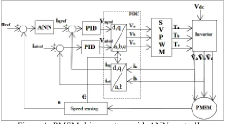
The operation of PMSM drive system is based on the measure of two phase currents and of the motor position. The rotor position feedback is necessary to generate the reference speed. In this case, incremental encoder (2500 pulse per revolution)has been attached. The measured phase currentsia and ib are transformed into the stator reference frame components ialpha and ibeta. Then, based on the position information, these components are transformed into the rotor frame direct and quadrature components id and iq. The speed and current controllers are PID discrete controllers. The inverse coordinates transformation is used for the computation of the phase voltages references, Va, Vb and Vc, applied to the inverter, starting from the values of voltage references computed in the d and q reference frame (Vd, Vq). Thus, the 6 full-compare SVPWM outputs of the DSP controller are directly driven by the program, based on these reference voltages. The code is developed only in C language, both for the main structure of the application and for the time-critical parts (as controllers, coordinates transformation, etc) The direct current component reference idis set to 0 because of the case corresponding to the motion of the motor in the normal speed range, without considering a possible field weakening operation.Figure 1 is the diagram of current control loop using FOC technology based on proposed ANN speed controller.
Figure 1: PMSM drive system with ANN controller
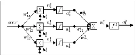
Proposed ANNController Structure
[image:2.612.315.546.498.626.2]perceptron neural network control is developed. Based on the type of the task to be performed, the structure of the proposed ANN speed controller is shown in Figure 2 (NooradzianieMuhd. Zin et al. 2013)
Figure 2: Block diagram of ANN controller for PMSM drive system.
The controller consists of input layer, hidden layer and output layer. Based on number of the neuron in the layers, the ANN is defined as a 1-3-1 network structure. The first neuron of the output layer is used as a torque reference signal (a21=mf). The connections weight parameter between
jth and ith neuron at mth layer is given by wmij, while bias parameter of this layer at ith neuron is given by bmi. Transfer function of the network at ith neuron in mth layer and output function of neuron at mthlayer is defined by:
∑
− = − + = 1 1 1 m S j m i m j m ij mi w a b
n (5)
The output function of neuron at mthlayer is given by:
) ( im
m m i f n
a = (6)
Where fis activation function of the neuron. In this design the activation function of the output layer is unity and for the hidden layer is a tangent hyperbolic function given by:
1 1 2 ) ( 2 − + = − m i n m i m e n f (7)
Updating of the connection weight and bias parameters are given by:
( )
( 1) ( )
m m
ij ij m
ij
F k
w k w k
w α ∂ + = − ∂ (8) m i m i m i b k F k b k b ∂ ∂ − =
+1) ( ) ( )
( α (9)
wherek is sampling time, α is learning rate, and F performance index function of the network.
Online Scheme of the Proposed ANN
After the neural network architecture is modelled, the next stage defines the learning model to update network parameters. By this learning capability, it makes the ANN suitable to be implemented for the system with motor
parameters which are difficult to define and vary against with environment. The training process minimizes the error output of the network through an optimization method. Generally, in learning mode of the neural network controller a sufficient training data input-output mapping data of a plant is required. Since the motor parameters of the PMSM drive vary with temperature and magnetic saturation, the online learning Back propagation algorithm is developed. Based on first order optimization scheme, updating of the network parameters are determined. The performance index sum of square error is given by:
∑
= i i k e kF ( )
2 1 )
( 2 (10)
) ( ) ( )
(k t k a k
ei = i − i (11)
where:ti is target signal
ai output signal on last layer.
The gradient descent of the performance index against to the connection weight is given by:
m ij m i m i m ij w n n F w F ∂ ∂ ∂ ∂ = ∂ ∂ (12)
The sensitivity parameter of the network is defined as:
m i m i n F s ∂ ∂ = (13) m i m i m i m i n a a F s ∂ ∂ ∂ ∂ = (14)
Gradient the transfer function again to the connection weight parameter is given by:
1 − = ∂ ∂ m i m ij m i a w n (15)
From substitution equation (13) and (15) into (8) the updating connection parameter is given by:
) ( ) ( ) ( ) 1 ( 1
1k w k s k a k
wijm− + = im−i −αim im− (16)
With the same technique the updating bias parameter is given by: ) ( ) ( ) 1 ( 1 k s k b k
bim− + = im−i −αim (17)
RESULTS AND DISCUSSION
The proposed model has been developed by Matlab/Simulink. The simulation block diagram for the proposed PMSM drives system with ANN is shown in Figure 3. The simulation block diagram has been created in order to download all the proposed system into DSP board.
hardware is interfacing with system by using TMS320F28335 DSP controller that the program will be downloaded. While, the PMSM equipped with 500-line quadrature incremental encoder (2500 pulse per revolution) is used.Results for each testing wererecorded by interfacing data acquisition (DAQ)with LabView software.
Alf*
Bet* an
bn
cn sv pwm1 1000 re ference spe ed
0 id_re f1
24 conv ert to rpm 2*pi/60
conve rt to rad/se c1 2*pi/60
conve rt to rad/ec2
foc26
pulse_counting1 S-Function2
dac_ac_noyaNew1
w ref mf NN Controller
double double
C280x
GPIO DO GPIOx
GPIO 4 C280x
GPIO DO GPIOx
GPIO 2 C280x
GPIO DO GPIOx
GPIO 0 F28335 eZdsp C28x3x
GPIO DI GPIOx
Digital Input C280x/C28x3x
[image:4.612.318.548.52.203.2]ADC B
[image:4.612.68.293.147.276.2]Figure 3: The simulink block diagram of the proposed PMSM drive system with ANN.
Figure 4: Experimental setup for proposed PMSM drive system with ANN
In order to verify the validity of the proposed PMSM drive system with ANN, both online and offline ANN system has been testfor a variety of speed. Different operating speed is tested, which is constant speed reference 1000rpm, step up speed reference is varying from 400rpm to 900rpm and step down speed reference is varying from 900rpm to 600rpm for both systems. All the results are shown in Figure 5 to Figure 10.
0 1 2 3 4 5 6 7 8 9 10
0 200 400 600 800 1000
Time (sec)
S
p
e
e
d
(
rp
m
)
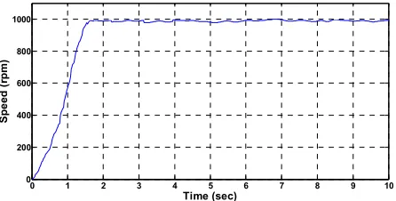
Figure 5: PMSM drive system with online ANN for constant speed reference 1000rpm
0 1 2 3 4 5 6 7 8 9 10
0 200 400 600 800 1000
Time (sec)
S
p
e
e
d
(
rp
m
[image:4.612.68.300.332.463.2])
Figure 6: PMSM drive system with offline ANN for constant speed reference 1000rpm
From the resultsin Figure 5 and Figure 6, it shows that by using an online ANN speed controller produced a better start-up performance compare to the offline ANN speed controller where the settling time more faster than offline speed controller in achieving desired output speed. The settling time for online ANN speed controller is 1.6sec while 2.74sec of settling time for offline ANN speed controller. Moreover in speed achieving for both system, an online ANN speed controller achieved 990rpm from the 1000rpm speed reference while offline ANN speed controller achieved 980rpm from the 1000rpm speed reference.Based on result from figure 5 and Figure 6, thedifferencepercentage for settling time between offline ANN and online ANN is 52.54% improved. Meanwhile, the rpmpercentage is 1.02% improved.
10 11 12 13 14 15 16 17 18 19 20
0 200 400 600 800 1000
Time (sec)
S
p
e
e
d
(
rp
m
)
Figure 7: PMSM drive system with online ANN for step up response from 400rpm to 900rpm
10 11 12 13 14 15 16 17 18 19 20
0 200 400 600 800 1000
Time (sec)
S
p
e
e
d
(
rp
m
)
Figure 8: PMSM drive system with offline ANN for step up response from 400rpm to 900rpm
Refer to the Figure 7 and Figure 8, it is also shows that by using an online ANN speed controller produced a better step up performance compared to the offline ANN speed controller where the settling time more faster than
DSP Board
Current Sensor PMSM Inverter
[image:4.612.319.540.403.515.2] [image:4.612.319.540.545.677.2] [image:4.612.71.294.603.716.2]offline speed controller in achieving desired output speed. Their settling time is1.32sec and 2.14sec respectively. It is also same in speed achieving performance which is an online ANN speed controller achieved 390rpm and 890rpm from the speed reference 400rpm and 900rpm compared to offline ANN speed controller which is reduced 10rpm respectively from online ANN speed controller in speed achieving. Difference percentage between offline ANN and online ANN for the result of settling time is 47.4% improved and speed is 2.6% improved for 400rpm reference speedand 1.13% improved for 900rpm reference speed. An online ANN can adapt variety condition because of their system always update the parameter even though one of the parameter during testing such as changing of temperature. In other words the weight and bias is updated together with the testing process.
20 22 24 26 28 30 32 34 36 38 40
0 200 400 600 800 1000
Time (sec)
S
p
e
e
d
(
rp
m
[image:5.612.70.292.267.388.2])
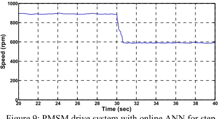
Figure 9: PMSM drive system with online ANN for step down response from 900rpm to 600rpm
20 22 24 26 28 30 32 34 36 38 40
0 200 400 600 800 1000
Time (sec)
S
p
e
e
d
(
rp
m
)
Figure 10: PMSM drive system with offline ANN for step down response from 900rpm to 600rpm
While, by referring to the Figure 9 and Figure 10, it is also shows that by using an online ANN speed controller produced a better step down performance compared to the offline ANN speed controller where the settling time more faster than offline speed controller in achieving desired output speed. Their settling time is 0.66sec and 1.46sec respectively. It is also same in speed achieving performance which is an online ANN speed controller achieved 890rpm and 590rpm from the speed reference 900rpm and 600rpm compared to offline ANN speed controller which is reduced 10rpm and 5rpm respectively from online ANN speed controller in speed achieving.Difference percentage between offline ANN and online ANN for the result of settling time is 75.47% improved and speed is 1.13% improved for 900rpm reference speed and 0.85% improved for 600rpm reference speed.
So, for the result difference percentage for constant speed 1000rpm, step up response and step down response can be conclude that by using online ANN will be 1.35% improved in average for speed achieving. While, 58.47% improved in average for settling time.
CONCLUSION
This paper has presented the modelling and hardware implementation of the field oriented control for PMSM drive system using online and offline neural network controller. The effectiveness of the proposed method is verified by develop the system in MATLAB-simulink program and experimental by using Digital Signal Processing board and interfacing DAQ with LabView software in order to recorded the result . The results show that the proposed an online ANN controller produce significant improvement control performance for controlling speed reference variations condition compared to offline ANN system especially for settling time which is 58.47% improved in average While 1.35% improved in average for speed achieving. It can conclude that by using proposed controller, the settling time and speed achieving can be improved significantly.
REFERENCES
Sergaki, E.S. et al., 2008. Fuzzy Logic based OnlineElectromagnetic Loss Minimization of Permanent Magnet Synchronous Motor Drives.In ICEM 2008.18thInternational Conference.pp.1-7, 6--9.
Pillay P. & Krishnan R. 1989.Modeling, Simulation, and Analysis of Permanent-Magnet Motor Drives, Part 1: The Permanent-Magnet Synchronous Motor Drive. In Industry Applications, IEEE Transactions, pp. 265--273.
Wong L.K. et al. 1998.Combination of Sliding Mode Controller and PI Controller using Fuzzy Logic Controller. In IEEE International Conference on Fuzzy System, vol.1,
pp. 296--301.
MohdMarufuzzaman et al., 2010. FPGA Implementation of an Intelligent Current Dq PI Controller for FOC PMSMDrive. In International Conference on ComputerApplications and Industrial Electronics (ICCAIE), pp 602.
Yang.Yi et al., 2003. Implementation of an Artificial neural network based real time adaptive controller for an Interior PMSM. In IEEE Transaction On Industry Application, vol. 39, pp. 96--103.
Narenda K.S. &Parthasarathy K. 1990.Identification and Control of Dynamical Systems Using Neural Networks. In
IEEE Transaction Neural Network, pp. 4--27.
NooradzianieMuhdZin&WahyuMulyoUtomo et al.,2013. Speed Control of Permanent Magnet Synchronous
Motor using FOC Neural Network. In Information
Technology Convergence, Lectures Notes in
ElectricalEngineering, Vol. 253, pp 295-- 303.
WahyuMulyoUtomo&NooradzianieMuhdZin et al.