Abstract—Measuring a tool tip interface temperature has never been an easy task to achieve using thermal couples due to the hostile environment in which thermal couples have to work. Limited success has been achieved from the use of infra-red pyrometers, as the chips are in direct line of sight of the cutting zone. Calculated values (for example, using Cook’s equation) are limited in their usefulness when the generated heat is being continually cooled by flood coolant. This research shows that a computational computer model of the cutting zone can be an effective method of obtaining the tool tip temperature while being cooled. Being able to calculate the tool tip temperature using a computer model allows the effects of changes made to the machining parameters to the cutting zone temperature to be realised. This includes finding the optimum cooling method for particular machining parameters.
Index Terms—Optimum machining parameters, Cook’s equation, computational computer model, cutting zone, hostile environment
I. INTRODUCTION
he main functions of a cutting fluid are lubricating and cooling the cutting tool. Jayal et al. [1] expanded this to include chip transport from the cutting zone, an increase from two to three functions of cutting fluids. In addition to this coolant provides temporary protection against oxidation and corrosion, which can be classed as an important secondary function. For these reasons it is apparent that coolant has an important role to play in metal cutting, and any alternative cooling method would need to provide the same properties. The ambition of this research is to prove that flood coolant can be replaced for many machining applications. Traditionally the only way to show that coolant may be replaced by alternative cooling methods was by carrying out robust testing of the machining operation. An easier and quicker method is to apply an appropriate computer analysis to determine best the cooling method.
The mechanical energy consumed in a machining operation is converted into thermal energy [2] mainly by
Manuscript received March 10th, 2014; revised 31st March 2014; Effectiveness of Using CFD for Comparing Tool Cooling Methods
Brian Boswell is a Lecturer at Curtin University Perth Western Australia 6845, corresponding author phone: +61 8 9266 3803; fax: +61 8 9266 2681; (e-mail: b.boswell@ curtin.edu.au)
Mohammad Nazrul Islam is a senior Lecturer at Curtin University Perth Western Australia (e-mail: [email protected]).
S. A. Chowdhury is a PhD candidate at Curtin University Perth Western Australia (e-mail: [email protected]).
shearing the material, with a secondary heat being generated as a chip slides over the rake face of the tool tip. For this reason it is obvious that for whatever cooling method is used it is the effectiveness of dissipating the heat from the cutting zone that determines its usefulness. According to the National Institute for Occupational Safety and Health [3], metalworking fluids can be classified into four types:
(a) straight oils (b) soluble oils
(c) semi-synthetics and (d) synthetics
Metalworking fluids often contain a mixture of other substances including biocides, corrosion inhibitors, metal fines, tramp oils, and biological contaminants [3]. Literature review identifies several health, safety, and environmental issues that should be addressed with regard to the application of cutting fluid: (a) toxicity of the fluid components, (b) flammability of the fluid, and (c) fluid disposal [4]. According to the Occupational Safety and Health Administration (OSHA) in the USA [4], metalworking cutting fluids can cause adverse health effects through skin contact with contaminated materials, spray, or mist, and through inhalation from breathing a mist or aerosol. These effects include skin disorders, respiratory diseases, and cancer. In recent years, the application of cutting fluids in machining operations has attracted also immense scrutiny due to its adverse effects on the environment. Consequently, a vast amount of research has been undertaken to reduce the application of cutting fluids [5]. Despite these efforts the problem remains unsolved because the research has shown that the effectiveness of the cutting fluid fluctuates on a case-by-case basis. According to Astakhov et al. [6], experimental studies in metal cutting are expensive and time consuming. In addition, the results are valid only for the specific experimental conditions used. The results also depend on the accuracy of the calibration of the experimental equipment. However, it is believed that the problem can be solved by developing a numerical model to help select the amount of cutting fluid in a scientific way, which minimises the amount of coolant needed for effective cooling of the tool tip.
Computational Fluid Dynamics (CFD) was adopted to carry out the numerical analysis (this procedure is now relatively common place). Figure 1 shows a simple CFD model of an oblique cutting operation using flood cooling. Numerical methods have been applied for modelling machining operations. They can be applied in calculating
Effectiveness of Using CFD for Comparing
Tool Cooling Methods
S. A. Chowdhury, M. N. Islam, MemberIAENG, and B. Boswell
the temperature distribution and thermal deformation in the tool, chip, and workpiece:
(a) Finite Difference Method (FDM) (b) Finite Element Method (FEM) (c) Boundary Element Method (BEM)
[image:2.595.305.546.512.628.2]The FEM is used to simulate the temperature distribution the tool insert, work piece etc. FEM is also used to simulate the thermal deformation.
Fig. 1. Cutting fluid flow simulation in orthogonal metal cutting process
Numerical methods are an alternative approach to experimental studies. There are several numerical methods, but FEM is the most popular for metal cutting studies. FEM can predict the various outputs and characteristics of the metal cutting process such as the cutting force, stresses, temperatures, and chip geometry.
Umbrello et al. [7] implemented empirical tool wear models using numerical codes in order to validate capabilities of the models. Bruni et al. [8] concluded that analytical and artificial neural network models are capable of predicting the surface roughness under different machining conditions. Similarly, Khidhir and Mohamed [9] found that the experimental measurement of tool temperature at the cutting tool and workpiece interface is problematic, but the finite element simulation can be used for quick and accurate prediction of the tool temperature under various cutting conditions. Knowles [10] concluded that finite element analysis can be viewed as a technique for solving equations, and as such, it has found application in many other areas including fluid flow, lubrication, seepage, electromagnetic fields, heat transfer, biomechanics, and others. FEM is used with some models to predict the heat distribution of an object. In this research, thermal analysis is performed using the Finite Element Modelling Software ANSYS CFX, which is capable of simulating and analysing turning objects [11]. Shen [12] developed a thermal model using ANSYS. Koyama [13] also used Computation Fluid Dynamics (CFD) simulation with the CFX; which is general purpose CFD software for heat transfer and fluid flow analysis by ANSYS Inc. Mostofa et al. [14] used ANSYS CFX for a CFD simulation to investigate water jet air and abrasive velocity.
II. CUTTING TESTS AND SET-UP
Measurement of the actual cutting forces and power allows the CDF simulation to be validated against an actual cutting test. These important cutting forces were measured by a Kistler dynamometer which has a high natural frequency and gives precise measurement. Dynoware28 software was used to provide high-performance real-time graphics of the cutting forces, and is used for evaluation of the forces during machining. The heat dissipating effects of the air was improved by using a “Ranque-Hilsch Vortex Tube”, a device that can produce cold air and provide a cold jet of air to the tool interface. The Vortex Tube (VT) was set at 90 psi compressed air giving a volumetric flow rate of 11 SCFM and the lowest temperature recorded for these conditions was -11C. The MQL was delivered from a Uni-max cutting tool lubrication system which distributed atomised coolube lubricant to the cutting zone. This system operates on the same principle as a Serv-O-Spray allowing the lubricant to be sprayed from a single air source, which allows adjustment to the amount of lubricant delivered to the cutting zone. A traditional emulsified cutting fluid (Cocol ultra cut) was used for the flood test machining as this is suitable for a range of materials. The cutting tool selected for all of the tests was a Sandvik (PDJNR2525M15) tool with a coated tungsten carbide insert (DNMG432-PF4215). All cooling nozzles used during the tests were kept at approximately 25 mm from the tool during all tests. Cutting tests were carried out using three conditions; dry, flood, and combined cooled air with MQL. Typical machining practices were used in machining the 40 mm diameter workpiece using the parameters as given in Table 1.
TABLEI. MACHINING PARAMETERS
Cutting Speed m/min
DOC mm
Feedrate
mm/rev Cooling Method
150 1 0.25
Dry
Flood
Cooled air combined with Minimal quantities of lubrication
III. CFDANALYSIS
Fig. 2. CFD Modelling steps [15]
Super computers play an important role in the field of computational science, as they are capable of handling large volume of data at high speed. One of the examples of the use of super computers is weather forecasting. This is why the iVEC Super computer is ideal for the necessary computations in predicting the tool tip temperature. Ansys CFX software was used for the simulation of the CFD analysis of cutting fluid in the orthogonal metal cutting process. Ansys CFD solvers are based on the finite volume method, domain, which is discretised into a finite set of control volumes.
Fig. 3. The cell centered control volumes of Fluent and node-centered control volumes of CFX [16]
The step for CFD simulation is shown in Figure 2, (Pre-processing) which can be further divided into:
(i) defining the geometry (ii) meshing
(iii) defining the physical model i.e. the equations of motion, conservation etc.
(iv) defining the boundary conditions
In CFX, the simulation execution equations can be selected to be solved iteratively, and the post processer is used to analysis the results of the solution. One of the differences between Ansys CFX and Fluent is that the Fluent control volumes are cell-centered (i.e. they correspond directly with the mesh) while CFX control volumes are node-centered as shown in Figure 3.
The methodology used for the heat generated factors, and subsequent cooling process during machining for the CFD model to predict is shown in the block diagram Figure 4. In
[image:3.595.317.532.231.569.2]this model the generating heat considerations are depth of cut, feedrate, cutting speed and material properties workpiece and tool. The cooling considerations during cutting are different fluid quantity, velocity and properties. The first step of the model is to develop the geometry of the metal cutting process. This was generated by using Ansys Design Modeler. It is also possible to import tool geometry data from other CAD software. The next step produced the mesh for the geometry by using the Ansys Meshing function. The number of elements should be reasonably high to get a best output from the simulations. If the number of elements is low then the accuracy of the analysis will not be high. Therefore it is important to find a reasonable balance between accuracy and the run time.
Fig. 4. The methodology used for developing the numerical model
IV.RESULTS AND DISCUSSION
[image:3.595.53.286.467.536.2]the amount of cutting fluids used is crucial for the survival of the environment.
[image:4.595.63.273.85.257.2]
Fig. 5. Analytical tool interface temperature distribution by flood cooling for Table I cutting conditions
[image:4.595.68.269.438.634.2]There are several advantages if cold compressed air is used as a coolant in machining. It is readily available, safe to use, inexpensive, environmentally suitable, and most workshops have compressed air available near the machine. The limitation of using air as a coolant is that the tool and workpiece start to increase in temperature after a number of machining operations. Therefore, there is a need for the tool and workpiece to have additional cooling added. This problem does not exist with liquid cooling as liquid coolants cover the tool and workpiece and reduce the heat buildup during machining Figure 5.
Fig. 6. Analytical tool interface temperature distribution in dry machining for Table I cutting conditions
Tool life is one of the considerations to achieve sustainable machining. Tool life depends on the tool interface temperature and can be severely shortened at high temperature. Therefore, the temperature distribution simulation of the tool insert is useful in predicting the tool life for the three different cases i.e. dry machining, flood cooling and a combination of cold air and Minimum Quantity Liquid (MQL) cooling. In all three cases, the same heat generating parameters are considered for the simulations.
It was assumed that the mechanical work done during the metal cutting process was converted into the equivalent amount of heat. Total heat generation Ptotal was calculated
using the following Equation 1.
Ptotal = Ks x DOC x Feed rate x Cutting Speed (1)
The Specific Cutting Force Ks, primarily depends on the
work material and the feedrate. The value of Ks was
obtained from the tool manufacturer's data handbook [17]. The Specific Cutting Force, Ks, for the above condition is
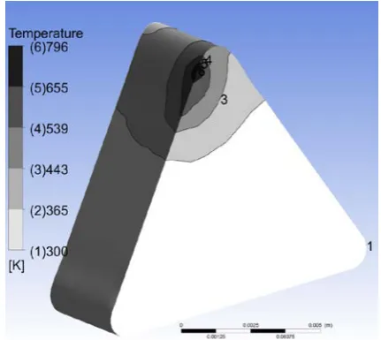
approximately 3645 N/mm2. In all three cases, the same heat generating parameters are considered in the simulations. Equation 1 was applied to calculate the heat inputs, using the machining parameters. It was taken that 3.3% of the total calculated heat entered into the tool tip insert as Fleisher et al. [18] he concluded that in general 92.7% of the heat is conducted away by the chips, 4% of the heat goes into the workpiece, and 3.3% of the heat enters into the tool tip. The CFD model was able to capture the cooling effect of the chips, removing the heat from the cutting zone, as shown by the tool interface Figure 6. The tool interface temperature is shown to be less for MQL and cold air simulation Figure 7. The inputs for this CFD analysis were as following:
(a) air flow was 10 SCFM (b) air temp was -10 oC
(c) liquid fluid temperature was 25 oC
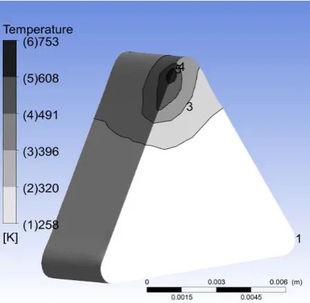
According to Figure 5 CFD simulation the chip tool interface temperature is found to be the lowest, when liquid cutting fluid was used as coolant. The initial coolant temperature was considered to be 25 o C, and the flow rate was 24 l/min. By using the CFD model it is now possible to predict the tool interface temperature for different cooling methods. For example, when the air mist temperature is reduced further as shown in Figure 8 there is a reduction of tool tip interface temperature. Heat distribution of the tool insert is only slightly reduced, as that shown in the Figure 9, when the cold air temperature is reduced to -50 oC.
[image:4.595.318.534.554.746.2]Obtaining the tool life is crucial in testing and detecting the effectiveness of the coolants. As a result of the simulation, the maximum interface temperature for the dry machining is 1296K as shown in Figure 6. Similarly the maximum interface temperature for cold air with MQL cooling is 796K. On the other hand, the maximum interface temperature for the flood cooling is 721K. This research has shown that the cold air with MQL can operate at a temperature that is effective for metal cutting. The temperature difference between the combination of cold air with MQL and flood cooling is only 75 degrees or 10%. This research has also shown that flood cooling may provide longer tool life according to the simulated result but the tool interface temperature difference between the combined of cold air with MQL and flood cooling is not enormous. Therefore, the possibility of tool failure in combined cold air with MQL will not be subsequently high when comparing that of flood coolant as the tool interface temperature difference is not very significant.
Fig. 8. The effect of mist air temperature on the tool interface temperature in combined cold air with MQL for Table I cutting conditions
Fig. 9. Analytical tool interface temperature distribution by combined -50 oC air and minimum liquid cooling for Table I cutting conditions
IV. CONCLUSION
This research showed that it was feasible to use CFD to determine the effectiveness of the cooling method, before cutting takes place. Virtual prototyping with ANSYS or similar soft should be used increasingly by manufacturing engineers around the world to help deliver their products to the market; faster, cheaper and more environmentally friendly. This was shown to be achieved by significantly reducing the amount of physical prototyping or machining testing required in determining the most effective tool cooling method. In addition to the cooling method CFD was an effective method of determining the best cutting parameters.
Even though the virtual model produced a slightly higher tool interface temperature for MQL, and cold air the resulting data was still good enough to identify the best cooling method. In conclusion, the combination of cold air with MQL can be an effective alternative to flood cooling, proving that environmental benefits are possible by adopting MQL and cold air cooling. Finally, by virtual modelling the different complex machining scenarios, allows additional cutting zone knowledge to be obtained, which would be otherwise difficult to achieve by traditional testing methods.
References
[1] Jayal, Anshu D., et al. "Machining Performance and Health Effects of Cutting Fluid Application in Drilling of A390. 0 Cast Aluminum Alloy." Journal of Manufacturing Processes 9.2 (2007): 137-146.
[2] Sutherland, John W. “Introduction to Heat in Machining”, Available: http://www.mfg.mtu.edu/ marc/primers/heat/heat.html
[3] NIOSH. Health hazard evaluation and technical assistance report: HETA. National Institute for Occupational Safety and Health 005-0227-3049, Diamond Chain Company, Indianapolis, Indiana. 2007 [4] OSHA. Metalworking Fluids: Safety and Health Best Practices Manual.
Salt Lake City: U.S. Department of Labor, Occupational Safety and Health Administration. 1999.
[5] Islam, M.N., Rafai, N.H., Heng, B.C. “Effect of Cutting Fluid Supply Strategies on Surface Finish of Turned Parts”. Advance Material Research Vols. 383-390 (2012) pp 4576-4584
[6] Astakhov, Viktor P., and José C. Outeiro. "Metal cutting mechanics, finite element modelling." Machining. Springer London, 2008. 1-27. [7] Umbrello, D., et al. "Prediction of Tool Wear Progress in Machining of
Carbon Steel using different Tool Wear Mechanismsl." International Journal of Material Forming 1.1 (2008): 571-574.
[8] Bruni, C., et al. "Surface roughness modelling in finish face milling under MQL and dry cutting conditions." International Journal of Material Forming 1.1 (2008): 503-506.
[9] Khidhir, Basim A., and Bashir Mohamed. "Study of cutting speed on surface roughness and chip formation when machining nickel-based alloy." Journal of mechanical science and technology 24.5 (2010): 1053-1059.
[10] Knowles, N. C. "Finite element analysis." Computer-Aided Design 16.3 (1984): 134-140.
[11] ANSYS CFX Technical Specifications, ANSYS, Inc., Canonsburg, PA 2010
[12] Shen, X., “Numerical modeling and experimental investigation of laser-assisted machining of silicon nitride ceramics”, Kansas State University, 2010
[13] Koyama, K., “CFD Simulation on LNG Storage Tank to Improve Safety and Reduce Cost”, Systems Modeling and Simulation, 2007, Part 1, Pages 39-43
[14] Mostofa, M. G., Kil, K. Y., Hwan, A. J.,” Computational fluid analysis of abrasive waterjet cutting head”, Journal of Mechanical Science and Technology, 2010, Volume 24, Number 1, Pages 249-252
[15] Introduction to CFD, Ansys CFX training materials, ANSYS, Inc., Canonsburg, PA 2010
[image:5.595.56.281.513.732.2][17] D. T. I. a. W. C., “Tool and Manufacturing Engineering Handbook,” 4th ed. vol. Vol 1. Dearborn, Michigan: Society of Manufaturing Engineers, 1983
![Fig. 3. The cell centered control volumes of Fluent and node-centered control volumes of CFX [16]](https://thumb-us.123doks.com/thumbv2/123dok_us/460871.544156/3.595.84.256.53.298/fig-centered-control-volumes-fluent-centered-control-volumes.webp)