Mechanical durability of superhydrophobic surfaces: the role of
1surface modification technologies
2
3
Jing-Hui Zhi1, Li-Zhi Zhang1,2*, Yuying Yan3, Jie Zhu3
4 5
1. Key Laboratory of Enhanced Heat Transfer and Energy Conservation of Education Ministry,
6
School of Chemistry and Chemical Engineering, South China University of Technology, Guangzhou
7
510640, China.
8
2. State Key Laboratory of Subtropical Building Science, South China University of Technology, Guangzhou
9
510640, China.
10
3. Fluids & Thermal Engineering Research Group, Faulty of Engineering, University of Nottingham,
11
Nottingham NG7 2RD, UK
12 13
[email protected]; [email protected] 14
Corresponding Author: Li-Zhi Zhang*
15 *E-mail: [email protected] 16 Tel/fax: 86-020-87114268 17 18 Abbreviations 19
SS: silica sol; 20
OA: octadecanoic acid; 21 HDFS: heptadecafluoro-1,1,2,2-tetrahydrodecyltrichlorosilane; 22 HTS: hexadecyltriethoxysilane; 23 TEOS: Tetraethoxysilica; 24 HMDS: hexamethyldisilazane; 25
HPW: High purity water; 26
SEM: scanning electron microscope; 27
AFM: atomic force microscope; 28
EDS: Energy dispersion spectroscopy; 29
XPS: X-ray photoelectron spectroscopy; 30
SCA: static contact angle; 31
SA: slide angle. 32
33
Abstract: Various surface modification technologies have been used to develop superhydrophobic 34
surface, however their durability has been recognized as the major obstacle for the real applications. 35
Here a quantitative investigation was conducted to evaluate the effects of different surface 36
modification methods on the surfaces’ mechanical durability. The superhydrophobic surfaces were 37
prepared by the combination of two surface roughing methods (etching and sandblasting) with 38
chemical modifications with four low surface energy materials: silica sol (SS), octadecanoic acid 39
(OA), heptadecafluoro-1,1,2,2-tetrahydrodecyltrichlorosilane (HDFS) and hexadecyltriethoxysilane 40
(HTS). XPS was used to analyze the elements composition and AFM was used to measure the 41
roughness of the surfaces. The durability of these surfaces was tested by a sandpaper abrasion 42
experiment. The collective results showed that the low surface energy materials had significant effects 43
on the surface roughness, which would then play an important role in the durability of these rough 44
surfaces modified by other three low surface energy materials. SS modified rough surfaces could bear 1
60 cycles of abrasion with 10 g weights on 1500 CW sandpaper. 2
3
Keywords: superhydrophobic; surface roughness; low surface energy material; durability; abrasion; 4
sandblast 5
6
1. Introduction 7
8
As a crucial aspect of interface chemistry, the wettability of a surface shows huge value in 9
fundamental and industrial applications. Since lotus leaves have been found possessing 10
superhydrophobic property, more and more researchers are motivated to study the superhydrophobic 11
phenomenon. When a water droplet can stay on the surface with a static contact angle larger than 150° 12
and a slide angle less than 10°, the surface is called superhydrophobic surface. These characteristics 13
make the surface achieve certain applicative properties in various fields, including antifogging [1-3], 14
self-cleaning [4, 5], anti-smudge [6, 7], corrosion resistance [8, 9] and anti-frost [10, 11]. In order to 15
achieve superhydrophobic surfaces where the droplets are in Cassie-Baxter state [12], great efforts 16
have been made. Milionis et al. [13] summarized the progress on fabrication, design and 17
understanding of mechanically durable superhydrophobic surfaces. Xue et al. [14] reviewed the 18
recent advances in developing mechanically durable, corrosion-resistant, self-healing and easily 19
repairable superhydrophobic surfaces, which would enable prolonged lifetime of 20
superhydrophobicity for practical applications in the future. The methods prepared superhydrophobic 21
surfaces can be represented by two steps: surface roughing and the subsequent chemical modification 22
by low surface energy materials. They are successful in the fabrication of superhydrophobic surfaces. 23
However, these surfaces are severely restricted by their poor mechanical durability in industrial and 24
practical uses. To enhance their mechanical properties, researchers have done a lot of work. Peng et 25
al. [15] fabricated a rough aluminum surface via a one-step anodization process and a subsequent 26
modification with 1H,1H,2H,2H-perfluorodecyltriethoxysilane (PDES) and stearic acid (STA). They 27
optimized the preparation parameters to fabricate the best rough morphology for the mechanical 28
durability. Zhang et al. [16] introduced micro/nano-pores in PTFE films in order to prepare more 29
durable superhydrophobic surface. To improve durability, Cho et al. [17] proposed a fabrication 30
process in which the dual-scale structures were prepared by combining sandblasting with surface 31
hydroxidion. Further, the roles of the low surface energy materials were studied. Scarratt et al. [18] 32
reported the effects of Teflon AF film wrinkles on the durability, but only one single low surface 33
energy material was considered. Vengatesh et al. [19] investigated the impact of long chain fatty acid, 34
perfluorinated fatty acid and perfluorosulfonicacid-polytetrafluoroethylene copolymer on the 35
superhydrophobicity of anodized aluminum surfaces, but the durability was not mentioned. These 36
studies indicate that a more quantitative analysis is necessary to study the effects of surface 37
modification technologies on the durability, which is the crux for practical applications. 38
In this paper, the effects of surface modification technologies on durability were quantitatively 39
studied. We used two methods to prepare different roughness surfaces: etching and sandblasting. For 40
the etching method to make rough surface, the micro-bumps and nano-flowers were both acquired by 41
chemical etching. For the sandblasting method to build rough surface, the sandblasting method was 42
We also used four low surface energy materials to subsequently modify the rough surfaces: silica sol 1
(SS), octadecanoic acid (OA), heptadecafluoro-1,1,2,2-tetrahydrodecyltrichlorosilane (HDFS) and 2
hexadecyltriethoxysilane (HTS). They were used to coat the rough surfaces through simple solution 3
immersion method. Through combining the two roughing surfaces with the four low surface energy 4
materials, eight kinds of superhydrophobic aluminum surfaces were fabricated. Then through 5
sandpaper abrasion experiments, the effects of the eight modification technologies on the durability 6
were investigated. Meanwhile a pencil hardness test was performed to evaluate the mechanical 7
robustness of the superhydrophobic surfaces like [20]. Long-term exposed test at ambient temperature 8
for 7 months was conducted to estimate the durability of the thin films. 9
10
2. Experimental 11
12
2.1 Materials
13 14
Pure aluminum plates [(50×30×0.8mm), 99.99% of purity] were purchased from Guangzhou 15
HengTai Materials Co., China. Tetraethoxysilica (TEOS), octadecanoic acid (OA) and 16
hexamethyldisilazane (HMDS) were obtained from Guangzhou QianHui Co., China. They were all 17
analytical reagents. Hexadecyltriethoxysilane (HTS) and heptadecafluoro1,1,2,2tetrahydrodecy -18
trichlorosilane (HDFS) were bought from Aladdin, ShangHai, China. Methanol, ethanol and acetone 19
were also analytical grade and they were used without any further purification. High purity water 20
(HPW) was prepared by a Purescience water purification system. 21
22
2.2Modification of Al surfaces
23 24
2.2.1 Procedure to prepare rough surfaces of Al
25 26
First method for rough surfaces (Method-etching): 27
Al plates were cleaned by ultrasonic bath with acetone, ethanol, and HPW for 5 min respectively 28
in sequence. Then they were dried by an air blower. The microstructures of the cleaned Al plates were 29
prepared by chemical etching in NaClO solution with a volume concentration 1:1 (NaClO: HPW). 30
The reaction was kept in 30 °C for 15 min [21]. After that, the plates were fished out and cleaned by 31
HPW 2~3 times. 0.2 g NaOH solid was put in a beaker with 100 ml HPW to form a solution. It was 32
then heated at 80 °C. The Al plates with microstructures were dipped in NaOH solution for 10 min at 33
80 °C to obtain nano-flower structures. In the end the plates were cleaned 3 times by HPW, and then 34
dried by the air blower for subsequent use. 35
36
Second method for rough surfaces (Method-sandblasting): 37
For obtaining micro-bumps structures, Al plates were sprayed by sandblast device with sand 38
particles at a pressure of 6 kgf cm2. The sizes of the sand particles were 500 mesh [17]. Then the sand 39
blasted Al plates were cleaned by ultrasonic bath with acetone, ethanol, and HPW for 5 min in 40
sequence before building nanostructures. Then they were dried by air blower. The method same as 41
the first one is used to prepare nano-structures. 42
2.2.2 Procedure for the preparation of superhydrophobic modifiers
1 2
Hydrophobic silica sol (SS) was prepared as follows [22]. 30 ml ethanol was added in a beaker. 3
2.1 ml TEOS was dripped into the ethanol and mixed by vigorously stirring for 10 min. Then 2 ml 4
HMDS was added to the solution slowly. After 30 min mechanical stirring, 3 ml HPW was dropped 5
into the mixture. After 2 h constant stirring, the mixture formed a transparent sol. The transparent sol 6
solution was placed at least 2 days for aging to form hydrophobic silica sol (SS). SS and ethanol were 7
mixed with a volume concentration of 1:5 for the subsequent use. 8
Octadecanoic acid (OA) solution was obtained through adding 2 g octadecanoic acid solid particles 9
into 100 ml ethanol with mechanical stirring at 50 °C till the solid particles were completely dissolved 10
[23]. Hexadecyltriethoxysilane (HTS) (0.6 g) was dropped into 100 ml methanol [20] to form solution. 11
And heptadecafluoro-1,1,2,2-tetrahydrodecyltrichlorosilane (HDFS) (0.5 ml) was dripped into 100 12
ml ethanol to form solution[24]. 13
14
2.2.3 Procedure for prepared superhydrophobic surfaces
15 16
The nanostructures were prepared by the same means, but the microstructures were made by 17
different means. For convenience, the first method making rough surface was called “etching” for 18
short and the second was called “sandblasting” for short. The samples were defined as “N-M”, where 19
N represented the method to build microstructures and M meant the modification materials. For 20
example, the sample etching-SS meant that the rough structures were made by the first method and 21
they were then chemically modified by SS. In this paper, 8 kinds of modified superhydrophobic 22
surfaces were made: etching-SS, etching-OA, etching-HTS, etching-HDFS, sandblasting-SS, 23
sandblasting-OA, sandblasting-HTS, and sandblasting-HDFS, respectively. 24
Etching-SS and sandblasting-SS were made through putting etching and sandblasting into SS for 25
18 h at ambient temperature. Their performances were researched after they were taken out and dried. 26
etching-OA and sandblasting-OA were obtained by soaking etching and sandblasting into OA 27
solution for 24 h at 30 °C. Then the samples were washed by ethanol and HPW for 2~3 times, 28
respectively. After this, the samples were dried in an oven at 80 °C for 1 h. etching-HDFS and 29
sandblasting-HDFS were prepared through adding etching and sandblasting to HDFS solution for 30 30
min at 25 °C followed by keeping them at 140 °C in an oven for 1 h. etching-HTS and sandblasting-31
HTS were achieved by soaking etching and sandblasting in HTS solution for 1 h at ambient, and then 32
heating at 130 °C for 0.5 h in a oven. 33
34
2.3 Characterization
35
The wettability of these samples was measured by a JC2000C1 contact angle system (Shanghai, 36
China) at ambient temperature with a 4 µl water droplet. The slide angles were measured by a drop 37
of water released onto the inclined substrate from a defined height. The minimum angle of the inclined 38
surface at which the drop completely rolling off the surface was recorded and that was the sliding 39
angle [25]. Each kind of sample was measured 3 times on different positions and the average value 40
was used. The morphological structures of the samples were observed using scanning electron 41
microscope (SEM, Merlin, LEO1530VP, Germany). Platinum was sprayed onto the samples before 42
using atomic force microscope (AFM, XE-100, Park, Korea) with a scan size of 5 µm × 5 µm. The 1
operating mode of AFM was contacting mode. Energy dispersion spectroscopy (EDS, Inca400, 2
Oxford, England) and X-ray photoelectron spectroscopy (XPS, Axis Ultra DLD, Krato, England) 3
techniques were used to obtain the chemical compositions of the modified samples. The samples were 4
magnified 1000× in EDS measurements. XPS Spectra were recorded using an X-ray source of Al Kα 5
radiation with a scan range of 0~1100 eV binding energy and referenced with respect to adventitious 6
carbon (C 1s: 284.6 eV). The chamber pressure was about 5 × 10⁻⁹ Torr. 7
2.4Durability test
8 9
The mechanical durability of the obtained samples was evaluated via a sandpaper-abrasion method 10
[26] illustrated in Fig. 1. The treated surfaces were placed face-down to the sandpaper (1500 CW). 11
Adding 10 g weights on the sample, the surface was moved along with a ruler by a force at a speed 12
of 5 mm/s. The static contact angles was measured after the abrasion test. The test was finished when 13
the contact angle was less than 150 °. 14
15
16
Fig.1. The schematic of sandpaper-abrasion test. 17
The mechanical robustness of the superhydrophobic surfaces was evaluated through a pencil 18
hardness test on the surfaces before and after exposed at ambient temperature for 7 months. The 19
durability of the thin films in the open air was estimated after exposed the surfaces outside for 7 20
months. 21
22
3. Results and discussion 23
24
3.1Formation of hierarchically structures
25 26
The rough structures were created on the cleaned aluminum surfaces through two methods, namely, 27
(sandblasting). The purpose was to achieve different micro-structures of rough surfaces. The SEM 1
images of bare aluminum and the prepared rough aluminum were provided in Fig. 2. 2
3 4
Fig.2. SEM images of (a): bare Al; (b): microstructural Al obtained by sandblasting; (c): 5
microstructural Al obtained by NaClO etching; (d): hierarchical structure obtained by sandblasting 6
combined with wet chemical etching (the amplified picture was inserted into the upper right corner); 7
(e): hierarchical structure obtained by two-step chemical etching (the nanostructures were depicted 8
in the upper right corner). 9
10
From the SEM images, it could be seen that the bare Al surface was almost smooth without any 11
rough structures. When it was sandblasted by sand as showed in Fig. 2 (b), the surface morphology 12
changed significantly and it had micro-scale unevenness. Compared to sandblasted surface, when the 13
surface was etched by NaClO solution as depicted in Fig. 2 (c), small particles appeared on the surface. 14
They were Al2O3 particles [21], which changed the surface morphology. These two structures of
15
rough surfaces created different roughness. The values of roughness were discussed in AFM 16
measurement. As revealed in Fig. 2 (d), after etched by sodium hydroxide solution, nano-flake 17
structures were formed on the micro-scale structures. Fig. 2 (e) showed similar nano-flake structures 18
as Fig. 2 (d). Two surfaces of different roughness were clearly showed from SEM images. For the 19
surfaces modified by the same low surface energy material, the roughness influenced the durability, 20
which would be discussed in the section of durability test. 21
22
3.2 Surface elemental composition
23 24
The elemental compositions of the fabricated surface samples were analyzed using EDS 25
spectroscopy and X-ray photoelectron spectroscopy (XPS) techniques. In Table 1, the elements 26
acquired on the surfaces could confirm that the surfaces were covered by the low surface energy 27
materials. In order to qualitatively analyze the elemental compositions, XPS was utilized. This 28
spectroscopy was one of the surface sensitive techniques used to provide information on the changes 29
in surface chemistry. XPS survey spectra were displayed in Fig. 3. It could be seen that the rough Al 30
surfaces without low surface energy materials showed only C 1s, O 1s, Al 2p peaks in Fig. 3 (a). 31
peak of Si 2p which was attributed to SS. The almost completely disappeared Al 2p peak indicated 1
that SS coated almost all areas of the rough surfaces, so that very little Al could be detected. When 2
the surface suffered physical wears, the SS became the first substance to be abrased and the rough 3
surfaces could be therefore protected. The surface morphology after SS coating could be seen in SEM 4
images in the following section. The intensity of C 1s peak in Fig. 3 (c) was obviously increased, 5
which confirmed that OA covered on the rough surfaces. The peaks of Si 2p, Cl 2p and F 1s seen in 6
Fig. 3 (d) indicated that HDFS was grafted on the surfaces. And the nearly disappeared Cl 2p peak 7
showed that HDFS hydrolyzed in the ethanol. In Fig. 3 (e), the increased intensity of C 1s peak and 8
the detected Si 2p peak proved that HTS existed on the rough surfaces. These results obtained from 9
XPS survey spectra were in accordance to those from EDS. 10
11
Table 1 12
Atomic percentages of bare Al, rough Al before and after modification. 13
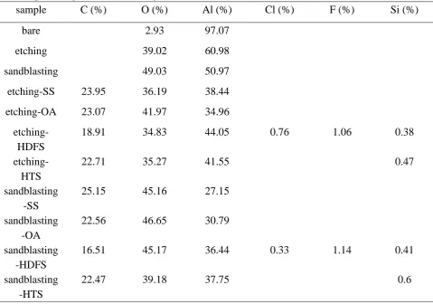
sample C (%) O (%) Al (%) Cl (%) F (%) Si (%)
bare 2.93 97.07
etching 39.02 60.98
sandblasting 49.03 50.97
etching-SS 23.95 36.19 38.44
etching-OA 23.07 41.97 34.96
etching-HDFS
18.91 34.83 44.05 0.76 1.06 0.38
etching-HTS
22.71 35.27 41.55 0.47
sandblasting -SS
25.15 45.16 27.15
sandblasting -OA
22.56 46.65 30.79
sandblasting -HDFS
16.51 45.17 36.44 0.33 1.14 0.41
sandblasting -HTS
22.47 39.18 37.75 0.6
[image:7.595.57.537.267.603.2]1
Fig.3. XPS survey spectra of (a): etched rough Al surfaces; (b): rough Al surfaces modified by SS; 2
(c): rough Al surfaces modified by OA; (d): rough Al surfaces modified by HDFS; (e): rough Al 3
surfaces modified by HTS. In the images, “etching” meant that the rough Al surfaces were prepared 4
by chemical etch, and “sandblasting” meant that the rough Al surfaces were made by sandblast. 5
6
To get more information in the changes of the surface compositions, XPS deconvoluted spectrum 7
of modified rough surfaces were collected in Fig. 4. Fig. 4 (a) and (b) showed the O 1s and Si 2p 8
peaks of SS. The etching-SS O 1s peak at 532.8 eV and the sandblasting-SS O 1s at 532 eV were 9
attributed to SiO2 [28, 29]. The Si 2p peaks at 103.6 eV and 103.5 eV of etching-SS and
sandblasting-10
SS came from SiOx,respectively [30-32]. These indicated that SS included many SiO2 particles which
11
could improve the durability of rough surfaces [33]. In Fig. 4 (c), the three peaks of O 1s at 532.3 eV 12
(C-O), 531.3 eV (C=O) and 530.2 eV (–OH) [19] were three kinds of valence in OA molecules, which 13
indicated that the valence state of oxygen atom did not change. So the covalent bonds between OA 14
molecules and the rough surface were not formed. The Al 2p peaks of etching-OA and sandblasting-15
OA still at about 74.0 eV which came from Al(OH)3 [34]further explained that the rough Al surfaces
16
did not react chemically with OA molecules and OA just filled in the pores by physical effect on the 17
rough Al surface. In Fig. 4 (e) and (g), the O 1s peaks of HDFS and HTS modified surfaces were all 18
around at 531.6 eV, attributing to the -Si-O-Al group [35]. The presence of Si 2p peaks around 101.95 19
eV in Fig. 4 (f) and (h) confirmed that -CO group existed [31, 36]. The formed -CO and -Si-20
O-Al groups illustrated that HDFS and HTS were grafted to the surface with covalent bonds. In most 21
cases, the three methoxyl groups in the HTS molecules were unable to be converted to hydroxyls 22
completely, and incompletely hydrolysed silane molecules could also be grafted to the substrates 23
during the later silanization processes, leading to a large degree of local disorder in the surface layer. 24
So the Si 2p peak of HTS was thus relatively more variable [37]. The reason for the fluctuating Si 2p 25
1
2
3
4
Fig.4. Deconvoluted XPS spectra of different chemical modification technologies on the two kinds 5
of rough surfaces (etching and sandblasting). SS: (a) O 1s and (b) Si 2p; OA: (c) O 1s and (d) Al 2p; 6
Since the depth of XPS detection was only 1.5 nm, and the height of SS stacked on the rough 1
surfaces was larger than 1.5 nm, so it’s hard to detect whether or not the covalent bonds between the 2
SS and the rough Al surface were formed. The rough surfaces could only be seen from the 3D images 3
of AFM. However, from the routes of SS fabrication, it could be concluded that there were no covalent 4
bonds formed between the SS and the rough Al surfaces. The ≡Si-O-Si(CH3)3 molecules had no active
5
groups to react with Al surface. The routes of SS fabrication were listed as follows [22]: 6
(CH3)3SiNHSi(CH3)3 + 2 H2O → 2 HO-Si(CH3)3 + NH3
7
Si(OCH2CH3)4 + 4 H2O → Si(OH)4 + 4 CH3CH2OH
8
≡Si-OH + HO-Si(CH3)3 → ≡Si-O-Si(CH3)3 + H2O
9
So the increased durability of SS modified surfaces could only be attributed to the existence of stacked 10
SiO2 inside the surfaces.
11 12
3.3 Surface morphological studies
13 14
SEM technique was used to observe the morphologies of surfaces after modified with different low 15
surface energy materials including SS, OA, HDFS and HTS. These materials were introduced 16
particularly to investigate their effects on durability property. Fig. 5 showed the images of rough 17
surfaces modified by hydrophobic materials. 18
19
Fig.5. SEM images showing the structures of (a): etching-SS; (b): etching-OA; (c): etching-HDFS; 20
(d): etching-HTS; (e): sandblasting-SS; (f): sandblasting-OA; (g): sandblasting-HDFS; (h): 21
The SEM images were visualized to reveal the results. It could be seen that the surfaces of etching-SS and 1
sandblasting-SS in Fig. 5 (a) and (e) were coated by silica sol with a mountain of SiO2 particles. The SS layer
2
consisted of nanoparticles had very high surface curvature. The nano particle aggregates increased the surface 3
curvature of convex particles, so the contact angles of SS modified surfaces were increased. [38] Thus, even 4
if some part of SS coating was frayed, the remaining particles with very high contact angles would ensure the 5
sample still have high contact angles. In Fig. 5 (b) and (f), the two rough surfaces were modified by OA which 6
just filled in the grooves on the surfaces without any covalent bond. When the surface was rubbed against 7
sandpaper, OA was worn off from surfaces easily, exposing the hydrophilic Al. Water would stick to the 8
surface and non-wettability was lost even though the Cassie state was still stable [39]. Fig. 4 (c) etching-HDFS, 9
(d) etching-HTS, (g) sandblasting-HDFS and (h) sandblasting-HTS showed that HDFS and HTS had no 10
obvious effect on morphologies. It indirectly showed that HDFS and HTS were grafted on the surfaces with 11
covalent bonds. When the rough surfaces modified by HDFS or HTS were frayed, the modified micro-12
structures would defend the surfaces from abrasion, [40] thus the surface could bear a certain degree of 13
abrasion, keeping the surfaces still superhydrophobic. 14
AFM, a topography observation tool, was used to observe the changes of the surface topography 15
and the roughness of various substrates before and after modification. Fig. 6 and Fig. 7 illustrated the 16
surface topography of Al plates before and after modified by low surface energy materials through 17
plane images and 3D images. From the topographical images in Fig. 6 and Fig. 7, the topography of 18
etching-SS, etching-OA, sandblasting-SS and sandblasting-OA had obviously changed, which was 19
consistent with the SEM images. As shown in the plane images (Fig. 6 (b)), the etching-SS surface 20
was coated with a large number of prills, while the etching-OA surface topography showed in Fig. 6 21
(c) became smooth without distinct micro-structures. Fig. 6 (d) etching-HDFS and 6 (e) etching-HTS 22
had no evident variations in the structures. AFM 3D images provided more direct evidence of 23
topography changes on the modified Al surfaces, which were outlined in Fig. 6 (i-v) and Fig. 7 (i-v). 24
The values of roughness (Rq) were calculated by the analysis software of AMF to explain the changes
25
of the rough surfaces and the values were listed in Table 2. The formula of the analysis software used 26
to calculate the Rq was given in equation (1), where L represented the length of the computational
27
domain in two-dimensional rough surface contour, 𝑦(𝑥𝑖) was the height of the measurement points
28
in two-dimensional rough surface contour, and n was the number of the sampling sites. 29
30
𝑅q= √1𝐿∫ [𝑦(𝑥)]0𝐿 2𝑑𝑥= √𝑛1∑𝑛𝑖=1𝑦(𝑥𝑖)2 (1)
31
32
From the equation (1), the value of Rq was larger when 𝑦(𝑥𝑖) was higher for an equal number of
33
sampling sites. In AFM measurement, all the samples were measured with a scan size of 5 µm × 5 34
µm. So it was concluded that the SS modified rough surfaces had the maximum Rq values and the
35
OA modified surfaces had the minimum Rq values. Meanwhile, for the superhydrophobic surfaces
36
modified by the same low surface energy material, the second roughing method had higher Rq values
37
than the first method. So the superhydrophobic surface of sandblasting-SS had the highest Rq values
38
0.474 µm and the etching-OA had the lowest Rq value 0.152 µm.
1
2
Fig.6. AFM plane images and 3D images of the rough Al surfaces made by etching-method before 3
(iv): etching-HDFS; (e) and (v): etching-HTS. The roughness parameters were achieved by profile 1
extraction of topographical images. Scan area 5×5µm2. 2
3
4
5
Fig.7. AFM plane images and 3D images of the rough Al surfaces made by sandblasting-method 6
sandblasting-OA; (d) and (iv): sandblasting-HDFS; (e) and (v): sandblasting-HTS. The roughness 1
parameters were achieved by profile extraction of topographical images. Scan area 5×5µm2. 2
[image:14.595.67.531.137.419.2]3
Table 2 4
Effects of roughness on wettability and durability. 5
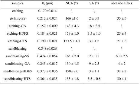
samples Rq (µm) SCA (°) SA (°) abrasion times
etching 0.170±0.014 \ \ \
etching-SS 0.212 ± 0.024 166 ±1.6 2 ± 0.3 35 ± 5
etching-OA 0.152 ± 0.009 143 ± 4.3 18 ± 3.5 \
etching-HDFS 0.184 ± 0.021 159 ± 1.0 3.5 ± 1.0 23 ± 4
etching-HTS 0.190 ± 0.021 153.5 ± 1.3 3 ± 1.2 21 ± 3
sandblasting 0.348±0.026 \ \ \
sandblasting-SS 0.474 ± 0.054 165 ± 2.0 2 ± 0.5 60 ± 2.5
sandblasting-OA 0.245 ± 0.017 150 ± 1.5 9 ± 2.5 4 ± 2
sandblasting-HDFS 0.373 ± 0.036 158± 2.0 3 ± 1.1 31 ± 2
sandblasting-HTS 0.364 ± 0.035 155 ± 1.8 3.5 ± 0.8 30 ± 4
6
3.4Surface wettability
7 8
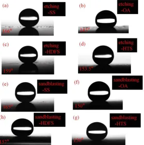
In order to describe the wettability of the modified rough surfaces, the static contact angles (SCA) 9
were tested using an optical contact angle instrument. The slide angles (SA) were measured by a drop 10
of water released onto the inclined substrate from a defined height. The minimum angle of inclined 11
surface at which the drop completely rolled off the surface was defined as the sliding angle. Fig. 8 12
displayed the images of SCA on the modified rough Al substrates. The values of SCA, SA and Rq
13
were presented in Table 2. The contact angles of the flat aluminum and the flat layer of each 14
1
Fig.8. Water contact angle images of (a): etching-SS; (b): etching-OA; (c): etching-HDFS; (d): 2
etching-HTS; (e): SS; (f): OA; (g): HDFS; (h): sandblasting-3
HTS. 4
[image:15.595.135.433.62.361.2]5
Table 3 6
The contact angles of the flat surfaces before and after being modified. 7
samples flat aluminum flat aluminum modified by
SS
flat aluminum modified by
OA
flat aluminum Modified by
HDFS
flat aluminum modified by
HTS
SCA(°) 89.4±3.0 145±2.3 92.4±2.5 120.7±1.2 105.1±2.0
8
In Table 2, it was observed that the SCA changed along with the roughness which was affected by 9
the low surface energy materials. For the same method to prepare rough structures, compared to un-10
modified surfaces, the roughness of SS modified surfaces was increased, but that of OA modified 11
surfaces was decreased. However the roughness of HTS or HDFS modified surfaces was similar to 12
the un-modified surfaces. So the surfaces modified by SS (etching-SS, sandblasting-SS) had the 13
largest contact angles of 166° and 165°, respectively. The contact angles were only 143° and 150° for 14
OA modified rough Al surfaces. The SCA on the surfaces modified by HTS or HDFS lied between 15
the SS modified and OA modified surfaces. However, the values of SCA on the HDFS modified 16
surfaces were larger than the HTS modified surfaces. The reason was that the surface energy of HDFS 17
was lower than that of HTS. Further, according to Table 3, on the flat aluminum, the SCAs on the 18
HDFS modified surface were larger than those on the HTS modified surface, which indicated that the 19
surface energy of HDFS was lower than that of HTS. It testified that the roughness of the rough 20
[image:15.595.59.541.465.532.2]surfaces must be prepared by the same method. If the rough surfaces were made through different 1
methods, the roughness was not a correct indicator to measure superhydrophobic behavior. 2
Meanwhile, for the same roughing method, it was very important to choose which low surface energy 3
material was used as the hydrophobic material to make the surface repelling water. 4
5
3.5Durability
6 7
Up to now, the durability of superhydrophobic surfaces is still an obstacle to practical applications. 8
Many researchers are working on this particular field to fabricate durable substrates [42, 20]. In this 9
paper, we have prepared eight kinds of superhydrophobic surfaces using two roughing methods and 10
four low surface energy materials to modify the rough surfaces. Through a sandpaper-abrasion 11
experiment, we evaluated the durability of these rough superhydrophobic surfaces to find the best 12
anti-wear rough surface. The modified rough Al plates were put on a 1500 CW sandpaper with 10 g 13
weights over the plates. Under the impetus of force, substrates moved slowly along with the ruler. 14
The contact angles were tested after each abrasion, and the abrasion times were recorded. Table 2 15
listed the abrasion times of all the rough superhydrophobic surfaces. From Table 2, it could be found 16
that the durability of the rough surface was proportional to the roughness of the surface. Fig. 9 showed 17
the effect of abrasion on the wetting properties of the superhydrophobic aluminum surfaces. 18
It could be seen in Fig. 9 that the SS modified rough surfaces were more durable than the rough 19
surfaces modified by other three kinds of modifiers. Since SS which included a mount of SiO2
20
particles stacked on the rough surfaces, it obviously enhanced the roughness of the rough Al surfaces. 21
In the early stages of wear, the SiO2 nanoparticles acted as roller bearings, leading to decreased
22
abrasive wear. The SS layer was much thicker than other low energy layers, which could be seen in 23
the SEM and AFM testing section. Therefore more abrasion cycles were required to be removed. In 24
addition, the SS layer consisted of SiO2 nanoparticles was with very high surface curvature and their
25
aggregates increased the surface curvature for convex particles, which resulted in the contact angle increasing. 26
Thus, even if some part of SS coating was frayed, the remaining particles with very high contact angles would 27
still help to maintain the superhydrophobicity of the surface. When SS stacking on the rough surface was 28
worn off, the protected Al rough surface was exposed to abrasion. The rough surfaces modified by 29
HDFS or HTS had similar durability properties. They both formed covalent bonds with the modified 30
surfaces and dispersed on the surface with monomolecular layers. The roughness of these substrate 31
surfaces was enhanced slightly. When these surfaces were rubbed, the Al surfaces were directly 32
exposed to abrasion, which were parallel to the SS modified surfaces after the SS stacking was worn 33
off. So HDFS or HTS modified surfaces were less anti-wear than the SS modified surfaces. The 34
surfaces modified by OA were the least durable surfaces. The OA molecules were just filled in the 35
grooves on the surfaces rather than by covalent bonds with the substrates. The Rq values of the OA
36
modified surfaces were decreased. When these surfaces were subjected to fray, the rough structures 37
of Al surfaces were easily rubbed off and the superhydrophobicity was easily lost. When the contact 38
angle was lower than 150°, the abrasion test was stopped. So the abrasion test was not performed on 39
the surface etching-OA. From the values of Rq and the times of abrasion cycles, though the
40
sandblasting-OA had larger Rq values than the etching-HDFS and etching-HTS surfaces, its times of
41
abrasion cycles was less than the latter two. The contact angle of sandblasting-OA was only 150 °C, 42
rough surfaces prepared by the second method were much durable than the first method prepared 1
surfaces. The reason was that the second method prepared surfaces had higher values of Rq than the
2
first method prepared surfaces. So when the surface had higher Rq values, its durable was better. This
3
is in agreement with the conclusion that the enhanced roughness from the nanostructures formed on 4
the microscale structures would improve the mechanical durability of superhydrophobic 5
surface.[14,39] 6
7
[image:17.595.58.540.173.510.2]8 9
Fig.9. Water contact angles of the superhydrophobic surfaces versus the abrasion cycles. 10
11
The pencil hardness test was conducted as follow [13]: a pencil with quantified hardness was 12
pressed firmly on the surfaces while moving along the surface at a constant speed. The pencil was 13
formed a 45 degree angle with the surface. The test was carried out on the surfaces before and after 14
being exposed in the open air for 7 months. The results were listed in Table 4. If a thin film was 15
coated on a substrate by van der Waals interactions, it usually could not endure 1B pencil hardness 16
tests. A good index of performance for a durable superhydrophobic surface was at least 2H. From 17
Table 4, it could be concluded that OA was grafted on the surfaces by van der Waals interactions, 18
which was in accordance to the XPS result that OA molecules did not form covalent bonds with the 19
surfaces. The surfaces modified by HDFS or HTS were durable due to the covalent bonds between 20
the HDFS/HTS molecules and the surfaces. As the SiO2 nanoparticles act as roller bearings, the
21
However, from the wettability of the surfaces exposed outdoor for 7 months, the HDFS modified 1
surfaces had higher SCA and lower SA than other candidates. It may be the reason that the surface 2
energy of HDFS was lower than others. 3
[image:18.595.58.540.153.322.2]4
Table 4 5
The hardness and wettability tests on the surfaces 6
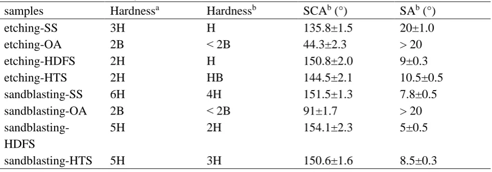
samples Hardnessa Hardnessb SCAb (°) SAb (°)
etching-SS 3H H 135.8±1.5 20±1.0
etching-OA 2B ˂ 2B 44.3±2.3 > 20
etching-HDFS 2H H 150.8±2.0 9±0.3
etching-HTS 2H HB 144.5±2.1 10.5±0.5
sandblasting-SS 6H 4H 151.5±1.3 7.8±0.5
sandblasting-OA 2B ˂ 2B 91±1.7 > 20
sandblasting-HDFS
5H 2H 154.1±2.3 5±0.5
sandblasting-HTS 5H 3H 150.6±1.6 8.5±0.3
a the thin film before exposed outdoor for 7 months
7
b the thin film after exposed outdoor for 7 months
8 9
4. Conclusions 10
11
In summary, two methods were used to build different rough structures, and four low surface 12
energy materials were respectively used to modify the rough substrates through solution immersion 13
method. After abrasion tests, the durability was investigated. Conclusions were drawn as follows: (a) 14
when SS that included some amount of SiO2 was used to modify the rough surfaces, SS could coat
15
on almost all areas of the Al surfaces. Hence, the roughness of the surfaces was increased greatly. (b) 16
When HDFS or HTS was used to modify the rough surfaces, the HDFS or HTS molecules would 17
form covalent bonds with Al surfaces and they were dispersed on the substrates in monomolecular 18
layers. So the roughness of these surfaces was changed slightly. (c) When OA was used to modify 19
the rough surfaces, the OA molecules filled in the grooves of the rough surfaces by physical effect. 20
So the roughness of the surfaces was reduced. (d) When the surfaces had larger roughness, they would 21
be more durable. So the SS modified surfaces that were prepared by the second method were the best 22
durability surfaces. It provided a direction for the fabrication of promising durable super-hydrophobic 23
surfaces. 24
25
Acknowledgements 26
27
This Project was supported by the National Science Fund for Distinguished Young Scholars of 28
China, No. 51425601. It was also supported by Natural Science Foundation of China, No. 51376064; 29
and by the National Key Research and Development Program, No. 2016YFB0901404. 30
31
References 32
[1] Z. Han, H. Guan, Y. Cao, S. Niu, L. Ren, Antifogging properties and mechanism of micron 1
structure in Ephemera pictiventris McLachlan compound eyes, Chin. Sci. Bull. 59 (2014) 2039-2044. 2
[2] Y. Chen, Y. Zhang, L. Shi, J. Li, Y. Xin, T. Yang, Z. Guo, Transparent 3
superhydrophobic/superhydrophilic coatings for self-cleaning and anti-fogging, Appl. Phys. Lett. 101 4
(2012) 033701 (033701-033704). 5
[3] A. Tricoli, M. Righettoni, S.E. Pratsinis, Anti-Fogging nanofibrous SiO2 and nanostructured SiO2
-6
TiO2 films made by rapid flame deposition and in situ annealing, Langmuir 25 (2009) 12578-12584.
7
[4] S. Zheng, C. Li, Q. Fu, W. Hu, T. Xiang, Q. Wang, M. Du, X. Liu, Z. Chen, Development of stable 8
superhydrophobic coatings on aluminum surface for corrosion-resistant, self-cleaning, and anti-icing 9
applications, Mater. Design. 93 (2016) 261-270. 10
[5] Z. Zhang, B. Ge, X. Men, Y. Li, Mechanically durable, superhydrophobic coatings prepared by 11
dual-layer method for anti-corrosion and self-cleaning, Colloid. Surface. A 490 (2016) 182-188. 12
[6] P.S. Brown, B. Bhushan, Mechanically durable, superomniphobic coatings prepared by layer-by-13
layer technique for self-cleaning and anti-smudge, J. Colloid. Interface. Sci. 456 (2015) 210-218. 14
[7] S. Peng, B. Bhushan, Mechanically durable superoleophobic aluminum surfaces with microstep 15
and nanoreticula hierarchical structure for self-cleaning and anti-smudge properties, J. Colloid. 16
Interface. Sci. 461 (2016) 273-284. 17
[8] J. Li, R. Wu, Z. Jing, L. Yan, F. Zha, Z. Lei, One-step spray-coating process for the fabrication of 18
colorful superhydrophobic coatings with excellent corrosion resistance, Langmuir 31 (2015) 10702-19
10707. 20
[9] S. Ammar, K. Ramesh, B. Vengadaesvaran, S. Ramesh, A. Arof, Amelioration of anticorrosion 21
and hydrophobic properties of epoxy/PDMS composite coatings containing nano ZnO particles, Prog. 22
Org. Coat. 92 (2016) 54-65. 23
[10] M.A. Sarshar, C. Swarctz, S. Hunter, J. Simpson, C.H. Choi, Effects of contact angle hysteresis 24
on ice adhesion and growth on superhydrophobic surfaces under dynamic flow conditions, Colloid. 25
Polym. Sci. 291 (2013) 427-435. 26
[11] P. Kim, T.S. Wong, J. Alvarenga, M.J. Kreder, W.E. Adorno Martinez, J. Aizenberg, Liquid-27
infused nanostructured surfaces with extreme anti-ice and anti-frost performance, ACS nano 6 (2012) 28
6569-6577. 29
[12] A. Cassie, S. Baxter, Wettability of porous surfaces, Trans. Faraday Soc. 40 (1944) 546-551. 30
[13] A. Milionis, E. Loth, I.S. Ba yer. Recent advances in the mechanical durability of 31
superhydrophobic materials. Adv Colloid Interfac. 229(2016) 57-79. 32
[14] C.H. Xue, J.Z. Ma, Long-lived superhydrophobic surfaces, J. Mater. Chem. A. 1(2013) 4146– 33
4161. 34
[15] S. Peng, D. Tian, X. Yang, W. Deng, Highly efficient and large-scale fabrication of 35
superhydrophobic alumina surface with strong stability based on self-congregated alumina 36
nanowires, ACS Appl. Mater. Inter. 6 (2014) 4831-4841. 37
[16] Y.Y. Zhang, Q. Ge, L.L. Yang, X.J. Shi, J.J. Li, D.Q. Yang, E. Sacher, Durable superhydrophobic 38
PTFE films through the introduction of micro- and nanostructured pores, Appl. Surf. Sci. 339 (2015) 39
151-157. 40
[17] H. Cho, D. Kim, C. Lee, W. Hwang, A simple fabrication method for mechanically robust 41
superhydrophobic surface by hierarchical aluminum hydroxide structures, Curr. Appl. Phys 13 (2013) 42
[18] L.R. Scarratt, B.S. Hoatson, E.S. Wood, B.S. Hawkett, C. Neto, Durable superhydrophobic 1
surfaces via spontaneous wrinkling of Teflon AF, ACS Appl Mater Interfaces 8 (2016) 6743-6750. 2
[19] P. Vengatesh, M.A. Kulandainathan, Hierarchically ordered self-lubricating superhydrophobic 3
anodized aluminum surfaces with enhanced corrosion resistance, ACS Appl Mater Interfaces 7 (2015) 4
1516-1526. 5
[20] L. Xu, Z. Geng, J. He, G. Zhou, Mechanically robust, thermally stable, broadband antireflective, 6
and superhydrophobic thin films on glass substrates, ACS Appl Mater Interfaces 6 (2014) 9029-9035. 7
[21] D. Lv, J. Ou, M. Xue, F. Wang, Stability and corrosion resistance of superhydrophobic surface 8
on oxidized aluminum in NaCl aqueous solution, Appl. Surf. Sci. 333 (2015) 163-169. 9
[22] Y.Y. Quan, L.Z. Zhang, Facile fabrication of superhydrophobic films with fractal structures using 10
epoxy resin microspheres, Appl. Surf. Sci. 292 (2014) 44-54. 11
[23] Y.Y. Quan, P.G. Jiang, L.Z. Zhang, Development of fractal Ultra-hydrophobic coating films to 12
prevent water vapor dewing and to delay frosting, Fractals 22 (2014) 1440002. 13
[24] S. Lee, W. Kim, S. Lee, S. Shim, D. Choi, Controlled transparency and wettability of large-area 14
nanoporous anodized alumina on glass, Scripta Mater. 104 (2015) 29-32. 15
[25] J. Zimmermann, F.A. Reifler, G. Fortunato, L.C. Gerhardt, S. Seeger, A simple, one-step 16
approach to durable and robust superhydrophobic textiles, Adv. Funct. Mater. 18 (2008) 3662-3669. 17
[26] L. Yin, J. Yang, Y. Tang, L. Chen, C. Liu, H. Tang, C. Li, Mechanical durability of 18
superhydrophobic and oleophobic copper meshes, Appl. Surf. Sci. 316 (2014) 259-263. 19
[27] P. Li, X. Chen, G. Yang, L. Yu, P. Zhang, Fabrication and characterization of stable 20
superhydrophobic surface with good friction-reducing performance on Al foil, Appl. Surf. Sci. 300 21
(2014) 184-190. 22
[28] R.P. Netterfield, P. Martin, C. Pacey, W. Sainty, D. McKenzie, G. Auchterlonie, Ion-assisted 23
deposition of mixed TiO2-SiO2 films, J. Appl. Phys. 66 (1989) 1805-1809.
24
[29] D. Sprenger, H. Bach, W. Meisel, P. Gütlich, XPS study of leached glass surfaces, J. Non-Cryst. 25
Solids 126 (1990) 111-129. 26
[30] W. Zhang, W. Liu, C. Wang, Characterization and tribological investigation of sol-gel Al2O3 and
27
doped Al2O3 films, J. Eur. Ceram. Soc. 22 (2002) 2869-2876.
28
[31] F. Cemin, L.T. Bim, L.M. Leidens, M. Morales, I.J. Baumvol, F. Alvarez, C.A. Figueroa, 29
Identification of the chemical bonding prompting adhesion of a-C:H thin films on ferrous alloy 30
intermediated by a SiCx:H buffer layer, ACS Appl Mater Interfaces 7 (2015) 15909-15917.
31
[32] W. Zhang, W. Liu, C. Wang, Characterization and tribological investigation of sol-gel Al2O3 and
32
doped Al2O3 films, J. Eur. Ceram. Soc. 22 (2002) 2869-2876.
33
[33] D. Kumar, X. Wu, Q. Fu, J.W.C. Ho, P.D. Kanhere, L. Li, Z. Chen, Development of durable self-34
cleaning coatings using organic-inorganic hybrid sol-gel method, Appl. Surf. Sci. 344 (2015) 205-35
212. 36
[34] S.Z. Chen, P.Y. Zhang, W.P. Zhu, L. Chen, S.M. Xu, Deactivation of TiO2 photocatalytic films
37
loaded on aluminium: XPS and AFM analyses, Appl. Surf. Sci. 252 (2006) 7532-7538. 38
[35] N. Saleema, D.K. Sarkar, R.W. Paynter, X.G. Chen, Superhydrophobic aluminum alloy surfaces 39
by a novel one-step process, ACS Appl Mater Interfaces 2 (2010) 2500-2502. 40
[36] Y. Liu, J. Liu, S. Li, J. Liu, Z. Han, L. Ren, Biomimetic superhydrophobic surface of high 41
adhesion fabricated with micronano binary structure on aluminum alloy, ACS Appl Mater Interfaces 42
[37] N.Y. Cui, C. Liu, N.M.D. Brown, B.J. Meenan, An exploratory study of the effects of the 1
dielectric-barrier-discharge surface pre-treatment on the self-assembly processes of a (3-2
Aminopropyl) trimethoxysilane on glass substrates, Appl. Surf. Sci. 253 (2007) 6932-6938. 3
[38] L. Boinovicn, A. Emelyanenko, The prediction of wettability of curved surfaces on the basis of 4
the isotherms of the disjoining pressure, Colloids and Surfaces A: Physicochem. Eng. Aspects. 383 5
(2011) 10–16. 6
[39] T. Verho, C. Bower, P. Andrew, S. Franssila, O. Ikkala, R.H. Ras, Mechanically durable 7
superhydrophobic surfaces, Adv. Mater. 23 (2011) 673-678. 8
[40] A.M. Emelyanenko, F.M. Shagieva, A.G. Domantovsky, L.B. Boinovich. Nanosecond laser 9
micro- and nanotexturing for the design of asuperhydrophobic coating robust against long-term 10
contact withwater, cavitation, and abrasion. Appl. Surf. Sci. 332(2015) 513-517. 11
[41] L. Mammen, X. Deng, M. Untch, D. Vijayshankar, P. Papadopoulos, R.d. Berger, E. Riccardi, 12
F.d.r. Leroy, D. Vollmer, Effect of nanoroughness on highly hydrophobic and superhydrophobic 13
coatings, Langmuir 28 (2012) 15005-15014. 14
[42] V. Kondrashov, J. Ruhe, Microcones and nanograss: toward mechanically robust 15
superhydrophobic surfaces, Langmuir 30 (2014) 4342-4350. 16
Table captions 1
Table 1 Atomic percentages of bare Al, rough Al before and after modified. 2
Table 2 Effects of roughness on wettability and durability. 3
Table 3 The contact angles of the flat surfaces before and after being modified. 4
Table 4 The hardness and wettability tests on the surfaces. 5
Figure Captions 6
Fig.1. The schematic of sandpaper-abrasion test. 7
Fig.2. SEM images of (a): bare Al; (b): microstructural Al obtained by sandblasting; (c): 8
microstructural Al obtained by NaClO etching; (d): hierarchical structure obtained by 9
sandblasting combined with wet chemical etching (the amplified picture was inserted into the 10
upper right corner); (e): hierarchical structure obtained by two-step chemical etching (the 11
nanostructures were depicted in the upper right corner). 12
Fig.3. XPS survey spectra of (a): etched rough Al surfaces; (b): rough Al surfaces modified by SS; 13
(c): rough Al surfaces modified by OA; (d): rough Al surfaces modified by HDFS; (e): rough Al 14
surfaces modified by HTS. In the images, etching meant the rough Al surfaces were prepared by 15
chemical etched and sandblasting meant the rough Al surfaces were made by sandblast. 16
Fig.4. Deconvoluted XPS spectra of different chemical modification technologies on the two kinds 17
of rough surfaces (etching and sandblasting). SS: (a) O 1s and (b) Si 2p; OA: (c) O 1s and (d) 18
Al 2p; HDFS: (e) O 1s and (f) Si 2p; HTS: (g) O 1s and (h) Si 2p. 19
Fig.5. SEM images showing the structures of (a): etching-SS; (b): etching-OA; (c): etching-HDFS; 20
(d): etching-HTS; (e): sandblasting-SS; (f): sandblasting-OA; (g): sandblasting-HDFS; (h): 21
sandblasting- HTS. 22
Fig.6. AFM plane images and 3D images of the rough Al surfaces made by etching-method before 23
and after modification. (a) and (i): etching; (b) and (ii): etching-SS; (c) and (iii): etching-OA; (d) 24
and (iv): etching-HDFS; (e) and (v): etching-HTS. The roughness parameters were achieved by 25
profile extraction of topographical images. Scan area 5×5µm2. 26
Fig.7. AFM plane images and 3D images of the rough Al surfaces made by sandblasting-method 27
before and after modification. (a) and (i): sandblasting; (b) and (ii): sandblasting-SS; (c) and (iii): 28
roughness parameters were achieved by profile extraction of topographical images. Scan area 1
5×5µm2. 2
Fig.8. Water contact angle images of (a): etching-SS; (b): etching-OA; (c): etching-HDFS; (d): 3
etching-HTS; (e): sandblasting-SS; (f): sandblasting-OA; (g): sandblasting-HDFS; (h): 4
sandblasting-HTS. 5
Fig.9. Water contact angles of the superhydrophobic surfaces versus the abrasion cycles. 6