Microcontroller Based Assistant System for Dumb
People
Jeevan Reddy K1, A Navaneeth2, A Vishwam3, G Pradeep4 1
Associate Professor, Sreenidhi institute of Science and Technology
2, 3, 4
Students, Electronics and Communication Engineering, Sreenidhi Institute of Science and Technology
Abstract: Digital vocalizer is a project for social purpose. We try to implement a system that build a communication gap between deaf individuals and hearing people as less as potential. Deaf individuals build use of language or gestures to create perceive what he/she making an attempt to mention however it's not possible to know by hearing individuals. So that we have a tendency to return on conclusion to create an easy model by taking a number of those gesture and convert it into audio and visual form so they will understand by everyone. For that we have a tendency to area unit creating use of arduino UNO Board as Atmega 328 Controller board to interface all of the sensors and actuators.
Basically, an Artificial Neural Network is that the conception of our paradigm. Some sensors area unit placed on the hand of deaf individuals that converts the parameter like finger bend hand position angle into electrical signal and supply it to Atmega 328 controller and controller take action consistent with the sign.
Keywords: Smart electronic aid, Artificial Neural Network, flex sensors, voice synthesis.
I. INTRODUCTION
“Gestures” and “Speech” are the expressions. These are mostly used in communication between human beings. In modern world there is a continuous demand for automatic appliances with increase in level of material comfort. The communication between audio-vocally impaired people poses a much tedious task. In human communication the utilization of speech and gestures is totally coordinated. Machine gesture and signing recognition is concerning recognition of gestures and signing mistreatment computers. A number of hardware techniques area unit used for gathering data concerning body positioning; generally, either image-based (using cameras, moving lights etc) or device-based (using instrumented gloves, position trackers etc.). Basically a synthetic Neural Network is that the conception of our epitome. Some sensors area unit placed on the hand of that converts the parameter like finger bend hand position angle into electrical signal and supply it to Atmega 328 controller and controller take action according to the sign.
One of the major challenges for people with hearing impairment is their fettered communication with the outside world. Limited access to technology owing to their inability to communicate has a significant impact on their life. Research is being done on several aspects to enhance their communication with the external world, of which, one is Microcontroller based assistant system for dumb people that works precisely on hand movement where different languages can be installed. This system conjointly offers high reliability and fast response.
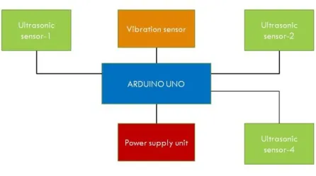
Figure 1: Working procedure
III. PROPOSED DESIGN
This project presents a prototype model and a system concept to provide an assistant system for dumb people. It consists of Data glove which contain flex sensors and accelerometer, Gesture detection system, speech synthesis and LCD display.
A. Data Glove
Data glove consists of two sensors, flex sensors and accelerometer. The output of the flex sensors is detected by the flex detection module, while the output of the accelerometer, and the overall gesture of the hand are detected by the gesture detection module. The gesture detection module provides associate 8-bit address to speech synthesis module; 8-bit address is completely different for every gesture. Speech Synthesis module speaks the message individual to handle received by it. This device is designed to help a physically challenged person to perform simple operations like switching on a light, fan etc. These actions can be performed by just a simple gesture like folding a finger and mapping the gestures to a suitable action.
1) Flex Sensor: Flex detector is largely a rheostat whose terminal resistance will increase once the detector is bent. The flex sensor’s internal resistance changes almost linearly with its flex angle. So this detector resistance will increase depends on surface one-dimensionality. So it's typically wont to sense the changes in one-dimensionality. commonly flex sensors implemented as voltage divider in circuit..
2) Accelerometer: Accelerometer module relies on the popular ADXL335 three-axis analog measuring system IC, that reads off the X, Y and Z acceleration as analog voltages. Accelerometer in this system is used as a tilt sensor, which checks the tilting of the hand. By measuring the amount of acceleration due to gravity, an accelerometer can figure out the angle it is tilted at with respect to the earth ADXL335 accelerometer is used in the system, the measuring device has AN analog output and this analog output varies from one.5 volts to three.5 volts. By sensing the quantity of dynamic acceleration, the measuring system will determine how briskly and in what direction the device is moving. There is an on-board voltage regulation, which enable you to power the board with 3V to 6V DC. Board comes totally assembled and tested with external parts put in. The enclosed zero.1uF capacitors set the information measure of every axis to 50Hz.
B. Audio Processing
The aPR33A series ar powerful audio processor beside high performance audio analog-to digital converters (ADCs) and digital-to-analog converters (DACs). APR33a3 Voice play back provides high quality recording and playback with 11 minutes audio at 8 KHz sampling rate with 16 bit resolution. The aPR33A series ar a completely integrated answer giving high performance and unequaled integration with analog input, digital processing and analog output functionality. The aPR33A series is specially designed for simple key trigger, user can record and playback the message averagely for 1, 2, 4 or 8 voice message(s) by switch, it is appropriate in straightforward interface or have to be compelled to limit the length of single message.
C. Voice Input
The circuit consists different input methods: microphone, line-in and mixture of both. The aPR33A series supported single channel voice input by electro-acoustic transducer or line-in. In transmitter section the ATmega microcontroller reads the values from the flex sensors and contact switch, this data is compared with the stored (calibrated) values. If the values do match to the values corresponding to a character, the character is sent to the raspberry pi module. Else, if the values do not match, recollection of data is done until a match is obtained for all flex sensor values. It is also possible to overwrite voice information and then record it. There can be blank message recording then. The voice input overwrites itself and bits of previous message can also be heard.
D. Voice Output
APR33A series can enter standby mode when RSTB pin drive to low. During chip in the stand by mode, this consumption is reduced to ISB and any operation are stopped, user also can not execute any new operate during this mode. The aPR33A series support 2 voice output mode, PWM and DAC. The PWM mode use VOUT1and VOUT2 pin to drive speaker directly without external components to save cost. The DAC mode use VOUT2 pin to output current signal. The MICG pin are drove to low throughout the message record or playback, and drove to high during idle or standby, user can detect MICG status to know chip is busy or not. User will get less current consumption by management RSTB pin specially in some application that concern standby current.
E. LCD Display:
There square measure loads of mixtures accessible like, 8×1, 8×2, 10×2, 16×1, etc. but the foremost used one is that the 16×2 LCD. LCD modules are very commonly used in most embedded projects, the reason being its cheap price, availability and programmer friendly. The appearance and the pinouts have already been visualized above now let us get a bit technical.16×2 LCD is named so because; it has 16 Most of us would have come across these displays in our day to day life, either at PCO’s or calculators Columns and 2 Rows. The function of this IC is to get the Commands and Data from the Microcontroller and process them to display meaningful information onto our LCD Screen.
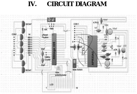
[image:3.612.200.422.406.559.2]IV. CIRCUIT DIAGRAM
Figure 2: Components connection.
V. WORKING
A. Tilt Detection
B. Bend Detection
Microcontroller deals with the bend sensors one by one. First of all the microcontroller checks the output of the first bend sensor, and calculates its pulse width, after the calculation of the pulse dimension of the primary bend sensing element the microcontroller saves its output. his module is based on a microcontroller-controlled circuitry. In this module one microcontroller is used and three ports of this microcontroller are in use. keeps on conniving the heart beat dimension of the bend sensors one by one, having calculated the heart beat dimension of the outputs of the 5 bend sensors, the microcontroller moves towards the next step of the module, i.e. gesture detection. Even a little bend of the finger is detected at this stage of the system, so the bending of the figure has infinite levels of bends, and the system is very sensitive to the bending of the finger. Now the bending of each finger is quantized into ten levels.
C. Speech Synthesis
Now the microcontroller knows that which data is send by the bend detection module, and what the meaning of this data is. Meaning means the microcontroller is aware of, if the hand is making some defined gesture and what should the system speak. This module of the system is consisted of a APR33A3 (speech synthesizer) IC, amplifier circuitry and a speaker. The last step of the system is to give voice to each defined gesture. For this purpose, a speech synthesizer IC, APR33A3 is used. Each word is consisted of some particular allophones and in case of Speech synthesizer IC each allophone has some particular addresses. The microcontroller receives the eight-bit knowledge from the “bend detection” module. It compares the eight-bit information with the predefined values. On the premise of this comparison the microcontroller involves grasp that that gesture will the hand create. This address is to be sent to the APR33A3 at its address lines, to make the speaker, speak that particular word.
VI. RESULTS AND DISCUSSION
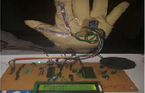
[image:4.612.187.426.397.551.2]The readings of flex sensor and accelerometer are sent to Arduino then Arduino process the information and sends the related code to the receiver via NRF transmitter. The code received by the NRF receiver was given to the Arduino then Arduino gives the signal to voice synthesis and LCD display the relevant information is displayed in the LCD display and voice output through speaker.
Figure 3: Outcome of Proposed System
VII. ADVANTAGES AND LIMITATIONS
A. It is a social cause project.
B. Deaf and mute people can easily communicate with normal people.
C. Easy to implement.
D. Easy to form amendment of sensing element windows in line with sporting hand.
E. Portable design works on 9V small Radio battery.
F. Audio as well as Visual output
G. Currently due to cost of sensors and funds limitation, limited gestures can be performed by single hand
VIII. CONCLUSION
This system converts the language into voice that is definitely intelligible by blind and normal people. The language is translated into some text type, to facilitate the deaf individuals
as well. This text is display on LCD. This project describes the design and working of a system which is useful for mute and deaf people to communicate with one another and with the normal people. The dumb individuals use their customary language that isn't simply intelligible by common individuals and blind people cannot see their gestures. This text is display on LCD. There will be plenty of future enhancements associated to the present analysis work, which includes:
A. Designing of wireless transceiver system for “Microcontroller and Sensors primarily based Gesture Vocalizer”.
B. Perfection in monitoring and sensing of the dynamic movements involved in “Microcontroller and Sensors Based Gesture Vocalizer”.
C. Designing of a whole jacket, which would be capable of vocalizing the gestures and movements of animals.
D. Virtual reality application e.g., replacing the conventional input devices like joy sticks in video games with the data glove.
E. The golem system to manage machine activity at remote sensitive sites.
Thus, the project contributes to the upliftment of the Deaf community and ensures that they also lead a life that is no different from the rest, thus breaking down the social stigmas which prevail in our society. Gesture vocalizer is a hand gesture-based interface for promoting communication among normal people and people with speech and hearing disabilities. This Digital Gesture Vocalizer is a social initiative project that helps to overpass the communication gap between normal people and disabled people. This will nearly bridge the communication gap gift between the deaf community and the normal world. Thus, the future enhancement of this system not only leads to an effective communication between dumb and normal but also to smart works.
REFERENCES [1] http://www.ijsrp.org/research-paper-1217/ijsrp-p7215.pdf
[2] .http://microcontrollerslab.com/adxl-335-accelerometer-interfacing/ [3] .https://www.elprocus.com/voice-recording-and-playback-circuit/ [4] https://learn.sparkfun.com/tutorials/flex-sensor-hookup-guide/all [5] https://www.microchip.com/wwwproducts/en/ATmega328p
[6] .https://www.analog.com/media/en/technical-documentation/data-sheets/adxl335.pdf
[7] https://www.ijser.org/researchpaper/Hand-gesture-recognition-and-voice-conversion-system-for-dumb-people-.pdf
[8] https://www.ijareeie.com/upload/2016/ncdi3c/5_EMBEDDED.pdf
AUTHOR PROFILE K Jeevan Reddy
Associate Profesor in Electronics and communication Engineering in Sreenidhi Institute of Science and Technology. UGC-SERO, Hyderabad sanctioned an Amount of Rs 3,60,000 (Rupees Three Lakhs Sixty Thousand only ) as Principal Investigator under Minor Project Oct 2016. Submitted one R&D project and 12 paper publications so far.
A Navaneeth pursuing under graduation B.Tech. in Electronics and Communication Engineering in Sreenidhi Institute of Science
and Technology in 2019. During 2015-2019, He worked as technical head in The Electronix Club-SNIST. During his period, he has guided several projects like Shoe for blind, CNC drawing machine, Smart irrigation system and Footboard accident prevention system.
Vishwam pursuing under graduation B.Tech. in Electronics and Communication Engineering in Sreenidhi Institute of Science and
Technology in 2019. During 2015-2019, He worked as Organizer in The Electronix Club-SNIST. During his period, he has guided several projects like Home automation using DTMF, RFID based attendance system and Hear rate monitoring system
G Pradeep pursuing under graduation B.Tech. in Electronics and Communication Engineering in Sreenidhi Institute of Science