In-Plane Compression Response of Regularly Cell-Structured Materials
Kanyatip Tantikom
1, Yoshihiro Suwa
2and Tatsuhiko Aizawa
3 1Graduate School of Engineering, The University of Tokyo, Tokyo 153-8904, Japan2Research Center for Advanced Science and Technology, The University of Tokyo, Tokyo 153-8904, Japan 3
Center for Collaborative Research, The University of Tokyo, Tokyo 153-8904, Japan
A quasi-static compression response of regularly cell-structured materials is studied by experimental and analytical procedures. A hexagonal close-packed cell-structure is fabricated by mechanical joining under compressive stress. The nominal stress-strain curve is typical to the cellular solids. It has three stages in deformation: linear elastic, plastic collapsing and densification regions. SEM-Servopulser is also used to describe the sequence of deformation images during uniaxial compressive test. Elasto-plastic model can predict quantitatively the compression behavior of copper cell-structured materials. Besides the relative density, the loading condition plays an important role on the deformation mode change and loading capacity. With increasing the contact radius ratio to cell wall thickness, the symmetric deformation changes itself to asymmetric deformation.
(Received October 21, 2003; Accepted December 19, 2003)
Keywords: cell-structured materials, metal honeycomb, compressive deformation, finite element analysis, symmetric and asymmetric
deformation modes, bonding contact area
1. Introduction
Two-dimensional cellular materials were first used as cores for panels and shells on aircraft in the 1940 s to reduce the weight and to increase payload and flight distance.1) Lightweight cellular structures have been utilized in several applications: e.g., packaging, energy absorbing devices, lightweight structures and so on.2) These types of cellular materials are characterized by high strength-to-weight ratios and/or large compressive loading capacity.3–7) Recently, a cellular solid becomes more attractive for multifunctional applications, where high loading capacity is required together with other functionalities: e.g., ultra-light structure for compact cooling, energy absorption and vibration control.8) This material design requires a structural topological design for efficient heat capacity together with loading capacity in the most efficient manner. The intervening space is used for flowing fluids to remove heat and for energy absorption by spatially distributing plastic deformations.9)These function-alities strongly depend on the matrix materials and cell geometry. Hence, new approach is indispensable to find a material solution to affordable lightweight components.
The optimal morphological design of cellular materials is one of the main issues in structural material design. The size, shape and topology of cell walls have a significant impact on the mechanical and thermal properties.10,11) In addition, precise understanding of material response is also necessary to describe the loading capacity.12,13)Gibsonet al.14)studied the mechanical behavior of honeycombs and stressed the effect of relative density and/or cell wall thickness on the stress-strain response. Papkaet al.15,16)analyzed the in-plane compressive crushing of honeycombs. They studied the effect of cell size/wall thickness, material properties, and their deformation pattern sequences. Chenet al.17)reported the effect of inclusions and holes on the stiffness and strength of metallic honeycombs by using finite element analysis. More profound understanding is required for the kinematic relation with mechanical response in loading to make topological optimization of two-dimensional cell-structured
materials.
In the present study, elasto-plastic deformation behavior of the two-dimensional regular cell-structure is investigated theoretically and experimentally under quasi-static uniaxial compression. A hexagonal close-packed copper cell-struc-ture is selected as a representative model since it has isotropic properties in all directions. This regularly cell-structured material provides an appropriate model for both fabrication and analysis. Finite element analysis is also used to describe the linear elastic and the post-yielding behavior of cell-structured materials. Both the deformation sequences as well as the nominal stress-strain relationships of cell-structured assemblies are obtained by experiments and analysis to understand the effect of various parameters on the compres-sive deformation behavior. The effects of number of cell-rows, relative density, contact conditions and also collapsing mode on the compressive behavior as well as the deformation mechanism are studied under displacement controlled quasi-static loading.
2. Experimental and Theoretical Procedure
Mechanical response of the regularly cell-structured materials is described theoretically by using finite element analysis and experimentally by using the uniaxial compres-sion tests.
2.1 Experimental procedure
(S45C) box. They were jointed in a vacuum furnace at 1023 K (750C). The box was held for 10.8 ks (3 h) to homogenize the microstructure of bonding area. Difference in thermal expansion coefficient between copper tubes and S45C box caused the compressive stress during heat treat-ment. Through this bonding, each tube was tightly connected with each other to form copper assemblies. Figure 1 depicts the regularly cell-structural array and contact area between two cell walls of copper cell-structured specimen.
Copper assemblies were subjected to compression at a quasi-static rate of 0.24 mm/min. Mechanical tests were carried out by the universal testing machine (Autograph, Shimadzu). The compression tests were also done by the Shimadzu Servopulser testing machine connected with a JEOL (JSM-5410LV) scanning electron microscope to observe the deformation behavior of cell-structured speci-men.
2.2 Theoretical procedure
The finite element analysis was used as a theoretical model to describe the compressive deformation behavior of the cell-structured materials. The related computational conditions were summarized in Table 2. The constituent tube of bonded
cell-assembly was assumed to be perfect in geometry with the radius of R and the wall thickness oft. The thickness was varied to control the relative density. The contact condition in bonding was also varied to understand the stress transfer through the cell-structured materials. Each cell wall was subdivided into the finite elements. Typical mesh subdivision was illustrated in Fig. 2. The special elements were used to trace the change of contact state of deforming cell-tubes. The target-element was utilized to predict the possibility of penetration of one cell-element to the others. While, the contact-element was necessary to characterize the stress-strain state between deforming elements in contact. The cell-wall material was assumed to be elasto-plastic with the J2 -flow theory. Its stress-strain relationship was represented by the bilinear isotropic hardening model. The elastic contribu-tion was characterized by the Young’s modulus while the elasto-plastic response was modeled by the plastic modulus. Considering that experimental specimen is uniaxially com-pressed by upper and lower rigid bars, two bars were modeled by the rigid surface. The lower rigid surface was fixed and the upper one was controlled to press the finite element model with the prescribed incremental displacement. The following simulation was conducted by the two-dimensional quasi-static analysis.
3. Results
3.1 Effect of the number of rows on the mechanical response
[image:2.595.71.540.82.276.2]The effect of number of rows in the copper cell-structured assembly on the in-plane compressive response was studied by both experiments and finite element analysis. The in-plane nominal compressive stress (c) is defined by dividing the load (P) by the original cross-sectional area of the specimen (A0): c¼P=A0. The nominal compressive strain ("c) is calculated by dividing the displacement of upper punch () by the original height of specimen (h0):"c¼=h0. As had been discussed in literatures,14–16,18) the nominal stress-strain curve of the cellular solids has typical, common features. It Table 1 Dimension of pure copper tubes in the experiment.
Material Outer diameter (OD) Thickness (t) OD/t Relative density
(mm) (mm) (%)
Pure copper 1000 100 10 29
Pure copper 800 80 10 29
Pure copper 800 50 16 19
Pure copper 500 50 10 30
250 µm 50 µm
[image:2.595.47.291.635.785.2]Fig. 1 Regularly cell-structural array and contact area between two cell walls.
Table 2 Computational conditions.
Program system ANSYS6.1
Type of element Triangular element with 6 nodes Number of elements 12944 elements
Number of nodes 28548 nodes
Young’s modulus E¼100GPa
Poisson’s ratio ¼0:35
Yield stress y¼30MPa
Stress-strain curve Bilinear isotropic hardening (rate-independent plasticity)
Plastic modulus ¼1GPa
Friction coefficient 0.3
Yielding condition J2flow theory
has three stages in the elasto-plastic deformation: linear elastic, plastically collapsing and densification stages. This intrinsic stress-strain response is often capped by the structural constraint and reinforcement.12,19)
In the present case, the loading condition overwhelms the intrinsic stress-strain response when the number of rows is small. Figure 3 compares the nominal stress-strain relations between three-row and five-row aligned specimens. The elastic region is vaguely observed in the three-row assembly while the linear elastic region is present in thec-"crelation for the five-row assembly. Both cell structured specimens have a positive slope with dc/d"c>0 in the collapsing region. In addition, the densification starts at the lower strain in the three-row specimen. These dissimilar features are caused by the different number of cells which are adjacent to the punches. The deformation of adjacent cells to the punches is constrained by the loading motion of punches, so that the top and bottom end rows have higher stiffness than other inner cells.
Finite element analysis was conducted to reconsider the effect of number of rows on the stress-strain curves. Figure 4 plots the nominal stress-strain relationships in the elastic and initial plastic regions for three, five and seven-row assem-blies. As seen in the experiments, the linear elastic region was seen in five-row and seven-row specimens while the elastic zone was vaguely observed in three-row assembly. The ratio
(rcell) of the number of adjacent cells to punches to the total number of cells is employed to consider the effect of number of rows on the stress-strain relationship. For the one-row specimen,rcell¼1:0, and with increasing the number of rows by three, five and seven, rcell decreases by 70%, 40% and 30% respectively. Agreement of stress-strain response between five and seven-row specimens assures that the regularly assembled specimen has intrinsic stress-strain relationship when rcell40%. In the following studies, five-row assembly is employed as a common geometric configuration for standard cell-structured materials.
3.2 Effect of the relative density on the mechanical response
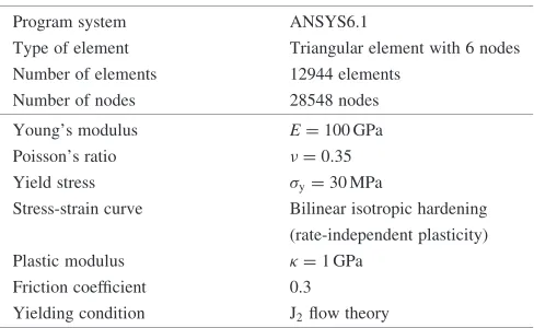
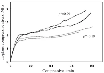
In order to study the effect of relative density on the compressive behavior, copper tube wall thickness was varied by 50 and 80mm, with the same diameter of 800mm, for the copper cell-structured assemblies. The relative densities () of these specimens were 0.19 and 0.29 respectively. Figure 5 shows the nominal stress-strain curves for two different specimens. No difference is seen at the early stage of elastic region. The stress-strain curve deviates from the elastic region around 8% in compressive strain. In the higher relative density specimen, the work hardening takes place in the collapsing stage, while the stress becomes nearly constant (dc/d"c0) in the lower relative density specimen. A sequence of in-plane compressive deformation, taken by SEM-Servopulser, was shown in Figure 6 for these two specimens with different relative densities. Uniform sym-metrical deformation was commonly observed in both cases. The relative density has little influence on the deformation mode.
In Fig. 7, the compressive deformation of five-row specimen was compared between the experimental result and the finite element model at the same nominal strain with "c¼0:15. The same initial configuration was assumed in the finite element analysis: R¼500mm, t¼100mm and ¼ 0:29. The calculated symmetric deformation is quantitatively in good agreement with experimental observation. In the following, this theoretical prediction is used to understand the effect of geometry and bonding condition on the compressive deformation behavior.
For theoretical analysis, the cell walls were modeled as
In-plane compressi
v
e stress, MP
a
Compressive strain
ρ* = 0.29
Fig. 3 Stress-strain relationships of copper cell-structures with different number of rows. (experiments)
Compressive strain
ρ* = 0.19
In-plane compressi
v
e stress, MP
a
Fig. 4 Calculated stress-strain relationships of copper cell-structures with different number of rows. (FEA)
In-plane compressi
v
e stress, MP
a
Compressive strain
ρ*=0.19
ρ*=0.29
[image:3.595.63.279.71.219.2] [image:3.595.319.537.603.757.2] [image:3.595.61.281.610.757.2]perfect annuli withR¼500mm,t¼59mmfor ¼0:19and
R¼500mm,t¼100mmfor ¼0:29. Figure 8 compares the specific compressive stress-strain relation in the elastic and initial plastic region with the same contact radius of
rc¼15mmbetween two materials. The initial work harden-ing coefficient as well as the collapsharden-ing loads, increase with the relative density. The higher relative density specimen has the higher specific stiffness in both elastic and initial plastic regions.
3.3 Deformation mode
In the finite element analysis of perfect cell-structured model under the quasi-static loading, the compressive deformation mode changes itself with loading. Figure 9 compares the deformation mode and global stress transfer between two finite element models under the same loading sequence. Table 3 listed the finite element modeling conditions. Initial geometric configuration is completely the same. The contact radius of bonded cell walls is only different between these two models. As illustrated in Fig. 9a),
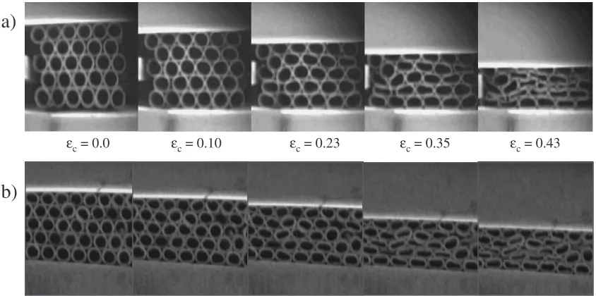
the five-row assembly was symmetrically compressed with loading. Except for the top and bottom ends, the cells at the center of assembly deformed with keeping their hexagonal array. Figure 10a) depicts the magnification of deformed geometry of this hexagonal array. The initial topological configuration is preserved during compressive loading, so that this type of cell-structured materials might be uniformly strained with increasing the compressive deformation. A cell-element, which is located at the center of array, is employed as a representative local unit. Then, its true strain or logarithmic strain " is plotted versus the compressive nominal strain"c. The fact that""c during compressive loading, assures that each cell-element deforms with nearly the same strain as the nominal strain. This homogenous straining sustains the symmetric deformation mode in global. On the other hand, as shown in Fig. 9b), the assembly was
ε c= 0.0 εc= 0.10 εc= 0.23 εc= 0.35 εc= 0.43
b)
a)
Fig. 6 Deformation sequence of pure copper assemblies. a)D¼800mm,t¼50mm, b)D¼500mm,t¼50mm.
Fig. 7 Comparison of compressive deformation between experimental result and theoretical calculation at"c¼0:15.
t = 59 µm t = 100µm
Compressive strain Symmetrical mode
R = 500µm
Specif
ic compressi
v
e stress, MP
a
[image:4.595.87.509.72.282.2]Fig. 8 Calculation of elastic and initial plastic region of copper cell-structures. (rc¼15mm)
Table 3 Two finite element model conditions to predict the compressive deformation of five-row assembly.
Outer radius,R Thickness,t Relative density Contact radius,rc Deformation
(mm) (mm) (%) (mm) mode
500 100 29 20.0 Symmetric
[image:4.595.324.531.320.463.2] [image:4.595.47.292.320.420.2] [image:4.595.50.551.733.786.2]asymmetrically compressed. In the successive two rows of assembly, one row shear-deforms in the right-hand side and the other, in the left-hand side. In fact, as shown in Fig. 11a),
the second and the forth rows from the top of assembly are compressed in the normal direction of line-m. While, the third one compressed in the normal to line-l. In this case, the logarithmic strain"of representative cell is not equal to the nominal strain "c; " increases abruptly when"c>0:15as shown in Fig. 11b). Since this cell element locally collapses along the line-l, it has little loading capacity for"c>0:15. This local collapsing behavior is accompanied with the significantly large spin rotation. Figure 12 compares the local stress transfer across the contact areas between two cell walls in the two deformation modes. In the symmetrical deforma-tion, the stress transfers in the symmetric parallelogram through the compressive loading. In the asymmetric defor-mation, the stress state localizes among the neighboring cells, forming the polygonal network for local stress transfer.
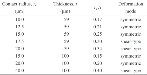
3.4 Effect of contact radius on the compression mode The bonding condition between cell walls is one of the most important parameters affecting on the mechanical behavior of cell-structured materials. In order to profoundly study this effect, perfect cell walls bonding with different contact radii (rc) were modeled and simulated. The model configurations are listed in Table 4. Figure 13 plots the calculated nominal stress-strain relationships of cell-struc-tured models with different contact radii. The stress-strain curves in elastic region seem to be indifferent to each model. In the collapsing region, however, dc/d"c>0 when rc is small. This dc/d"cdecreases with increasingrc, and, finally
εc=0.07
a) b)
εc=0.09
εc=0.11 εc=0.13
εc=0.15 εc=0.18
Fig. 9 Comparison of deformation mode and stress transfer between two finite element models under the same loading condition: a) symmetric deformation mode and b) asymmetric deformation mode.
εc = 0.026 εc = 0.110 εc = 0.145 εc = 0.154
εc = 0.163 εc = 0.166 εc = 0.168 εc = 0.171
a)
0.00 0.05 0.10 0.15 0.20 0.25
0 0.05 0.1 0.15 0.2 0.25
1 1
ε*
Local compressi
v
e strain,
ε
*
Global nominal compressive strain, εc
[image:5.595.310.548.69.386.2]b)
Fig. 10 Compressive straining behavior of representative cell in the symmetrically deforming hexagonal unit.
εc = 0.151 εc = 0.161 εc = 0.164 εc = 0.171
εc = 0.018 εc = 0.064 εc = 0.102 εc = 0.148
l
m
a)
0.00 0.05 0.10 0.15 0.20 0.25 0.30 0.35 0.40
0 0.05 0.1 0.15 0.2 0.25 0.3 0.35 0 10 20 30 40 50 60 70 80 90
Global nominal compressive strain, εc
Local compressi
v
e strain,
ε
*
ε*
Spin rotation angle,
ϕ
b)
[image:5.595.57.282.71.340.2] [image:5.595.48.289.392.709.2]when rc¼20mm, the compressive stress becomes nearly constant during compressive loading. This difference in the plastically collapsing region is caused by the deformation mode change. Table 5 summarizes the difference in the calculated deformation mode for various ratios of contact radius to the wall thickness. With increasing the ratio ofrc=t, the symmetric deformation mode changes itself to the asymmetric shear-deformation mode. In order to understand the effect ofrc=ton the stress-strain relation, the calculated nominal stress at "c¼0:1 is employed as an indicator of loading capacity. Figure 14 describes the effect ofrc=ton the loading capacity of the cell-structured materials. When they deform symmetrically, the compressive loading capacity increases with increasing the contact area ratio. When rc=t approaches to the critical value of (rc=t), the loading capacity becomes maximum where the mode change from
symmetric to asymmetric deformation takes place. Once the asymmetric shear-deformation becomes dominant, the load-ing capacity decreases monotonically withrc=t.
4. Discussion
The deformation mode in the collapsing region changes in the dependent manner on the ratio of contact radius to the cell wall thickness, or, rc=t. In particular, the elasto-plastic analysis reveals that the collapsing deformation mode changes itself from the symmetric deformation mode to the asymmetric shear deformation mode in the function ofrc=t. Whenrc=t<ðrc=tÞin Fig. 14, the loading capacity increases with increasingrc=torrc since much stress transfers across the cell contact area. The compressive stress transfers row by row through this contact area, so that uniform compression advances in the symmetric mode. When rc=t(rc=t), the 0
4.5E+9
9.0E+9
1.3E+10
1.8E+10
2.2E+10
2.7E+10
3.1E+10
3.6E+10
4.0E+11
[image:6.595.88.514.75.211.2]a)
b)
[image:6.595.307.543.253.543.2]Fig. 12 Local stress transfer across the cell-walls in a) symmetrical deformation mode and b) shear-type deformation mode.
Table 4 Finite element model configurations of copper cell-structured models.
Outer radius,R Thickness,t Relative density Contact radius,rc
(mm) (mm) (%) (mm)
500 59 19 10.0
500 59 19 12.5
500 59 19 15.0
500 59 19 17.5
500 59 19 20.0
500 100 29 15.0
500 100 29 20.0
500 100 29 40.0
Compressive strain
rc =21.2
0.00 0.02 0.04 0.06 0.08 0.10 0.12 0.14 0.16 5.0
10.0 15.0 20.0 25.0
rc =17.6
rc =14.1
rc =28.3
In-plane compressi
v
e stress, MP
a
[image:6.595.307.549.261.384.2]Fig. 13 In-plane stress-strain relationships in elastic and initial plastic region of copper cell-structured models (R¼500mmandt¼59mm).
Table 5 Deformation mode results from copper cell-structured models.
Contact radius,rc Thickness,t
rc=t
Deformation
(mm) (mm) mode
10.0 59 0.17 symmetric
12.5 59 0.21 symmetric
15.0 59 0.25 symmetric
17.5 59 0.30 shear-type
20.0 59 0.34 shear-type
15.0 100 0.15 symmetric
20.0 100 0.20 symmetric
40.0 100 0.40 shear-type
R¼500mmin all of the models.
0 5 10 15 20 25 30
0.18 0.23 0.28 0.33 0.38 0.43 0.48 0.53
In-plane compressi
v
e stress, MP
a
rc/t
Symmetrical mode
Asymmetric mode
ρ* = 0.19 (rc/t)*
[image:6.595.49.285.267.551.2] [image:6.595.328.525.413.540.2]shear deformation mode is mixed into the local stress state together with the symmetric one. Whenrc=t>ðrc=tÞ, only the shear collapsing deformation is favored for compressive deformation, so that the loading capacity decreases with increasingrc=t.
In the open cell-structured solid under compression, its constituent columns support the applied stresses and a column of open cells is representative of local stress transfer. As had been discussed in Ref. 14), both the bending and collapsing deformation of the column determine the loading capacity. In the present case, the compressive stress transfers through the cell wall and across the contact area. Hence, instead of a column in the conventional cell-structured materials, the local unit plays a significant role on the local stress transfer. From the calculated stress state in the compressed materials, the local unit is deduced. In the case of symmetrically collapsing deformation, the initial regular parallelogram network of ABCD is compressed to A’B’C’D’ in Fig. 15a). No distortion takes place, preserving the symmetric stress transfer. In this symmetric configuration, higherrc=tleads to increase of local loading capacity for this network. On the other hand, the original parallelogram network changes itself to more complicated polygonal network in the case of asymmetric, shear-type deformation mode, as shown in Fig. 15b). This local geometric change in regularity reflects on the global deformation mode change and the reduction of loading capacity of cell-structured materials.
5. Conclusions
The regularly copper cell-structured materials are fabri-cated by the mechanical joining method. Five-row assembly for geometric configuration is employed to investigate the intrinsic compressive stress-strain response of regularly
cell-structured materials. This intrinsic stress-strain response is characterized by the equivalent elastic stiffness and the collapsing deformation behavior. In particular, the collapsing deformation has two modes: symmetric deformation and shear deformation modes. Due to the elasto-plastic analysis of perfect cell-structured material model, both the relative density and the contact condition have significant influence on this selection of deformation modes. Higher loading capacity is attained in the symmetric deformation mode since the compressive stresses are uniformly transferred through the cell walls. Mechanical design of cellular materials has to consider this deformation mode change in order to improve the loading capacity in compression.
REFERENCES
1) Jim Kindinger: Light weight structural core, ASM Handbook, Vol.21 (2001)180–183.
2) Anthony G. Evans, John W. Hutchinson and Michael F. Ashby: Current Opinion in Solid State & Materials Science3(1998) 288–303. 3) A. M. Hayes, D. L. McDowell and J. K. Cochran,Jr: Proceedings of the
2002 TMS Annual Meeting in Seattle, Washington, Processing and Properties of Lightweight Cellular Metals and Structures, (2002) pp. 223–232.
4) J. L. Clark, J. K. Cochran, T. H. Sanders, K. J. Lee: Proceedings of the 2002 TMS Annual Meeting in Seattle, Washington, Processing and Properties of Lightweight Cellular Metals and Structures, (2002) pp.137–146.
5) H. Kanahashi, T. Mukai, Y. Yamada, K. Shimojima, M. Mabuchi, T. Aizawa and K. Higashi: Mater. Trans.42(2001) 2087–2092. 6) H. Kanahashi, T. Mukai, T. G. Nieh, T. Aizawa and K. Higashi: Mater.
Trans.43(2002) 2548–2553.
7) Y. Yamada , K. Shimojima , Y. Sakaguchi , M. Mabuchi, M. Nakamura,T. Asahina, T. Mukai, H. Kanahashi and K. Higashi: Mater. Sci. Eng.A280(2000) 225–228.
8) D. T. Queheillalt, D. J. Sypeck and H. N. G. Wadley: Mater. Sci. Eng. A, In Press, Feb 2001.
9) A. G. Evans, J. W. Hutchinson, N. A. Fleck, M. F. Ashby and H. N. G. Wadley: In Press, 2001.
10) T. Aizawa, H. Kanahashi and K. Tantikom: J. Japan Foun. Eng. Soc.74 (2002) 805–811.
11) Benjamin C. Church, Joe K. Cochran and Thomas H. Sanders, Jr.: Proceedings of the 2002 TMS Annual Meeting in Seattle, Washington, Processing and Properties of Lightweight Cellular Metals and Structures, (2002) pp.157–166.
12) V. P. W Shim and W. J. Stronge: Int. J. Mech. Sci.28(1986) 709–728. 13) K. Tantikom, H. Kanahashi, S. Yamamoto and T. Aizawa:
Mater.-Trans.44(2003) 1290–1294.
14) Lorna J. Gibson and Michael F. Ashby: Cellular solids Structure and Properties, 2nd edition, (Cambridge University Press, 1997). 15) Scott D. Papka and Stelios Kyriakides: Int.J. Mech. Phys. Solids.42
(1994) 1499–1532.
16) Scott D. Papka and Stelios Kyriakides: Int. J. Solids Struc.35(1998) 239–267.
17) C. Chen, T. J. Lu, N. A. Fleck: Int J. Mech. Sci.43(2001) 487–504. 18) J. M. Albuquerque, M. Fatima Vaz and M. A. Fortes: Scr. Mater.41
(1999) 167–174.
19) NASA Langley Research Center’s, High-Performance TEEK Poly-imide Insulation Foam Technology, from: http://www.nasatechnolo-gy.com/teek/pdf/BackgroundInfo.pdf.
A’
B’ C’
D’
A
B C
D A
B C
D
A’
B’ C’
D’ a)
b)
[image:7.595.48.292.72.232.2]Before loading During loading