Visual tracking of a GPS target within a FieldLab
FOSTER, L <http://orcid.org/0000-0002-1551-0316>, HELLER, B
<http://orcid.org/0000-0003-0805-8170>, GOODWILL, S
<http://orcid.org/0000-0003-0638-911X> and CURTIS, D
<http://orcid.org/0000-0002-2244-3318>
Available from Sheffield Hallam University Research Archive (SHURA) at:
http://shura.shu.ac.uk/8193/
This document is the author deposited version. You are advised to consult the
publisher's version if you wish to cite from it.
Published version
FOSTER, L, HELLER, B, GOODWILL, S and CURTIS, D (2014). Visual tracking of a
GPS target within a FieldLab. In: The engineering of sport. Procedia Engineering, 10
(72). Elsevier, 168-173.
Copyright and re-use policy
See
http://shura.shu.ac.uk/information.html
Procedia Engineering 72 ( 2014 ) 168 – 173
1877-7058 © 2014 Published by Elsevier Ltd. This is an open access article under the CC BY-NC-ND license (http://creativecommons.org/licenses/by-nc-nd/3.0/).
Selection and peer-review under responsibility of the Centre for Sports Engineering Research, Sheffield Hallam University doi: 10.1016/j.proeng.2014.06.044
ScienceDirect
The 2014 conference of the International Sports Engineering Association
Visual tracking of a GPS target within a FieldLab
Leon Foster
a*, Ben Heller
a, Simon Goodwill
aand David Curtis
aaSheffield Hallam University, Centre for Sports Engineering Research, Collegiate Crescent, Sheffield, S10 2BP
Abstract
The monitoring and videoing of a user’s movement within a “FieldLab” recreational facility is required to study the effectiveness of innovative equipment designed to increase physical activity.
A low cost alternative to current tracking systems based around the Global positioning system (GPS) was trialed for use within the Sheffield FieldLab. This low cost tracking system is based around a typical AndroidTM smartphone, which was used
as a wearable tracking sensor. The system was combined with a bespoke video surveillance system, which takes positional data and outputs appropriate camera parameters. In pilot work, participants’ GPS positional data was converted in real time to a pan tilt and zoom value. This allowed the targeted participant to be viewed in the centre of the video stream. Positional data was updated every second, allowing the camera to move and track the participant by keeping them at the centre of the video frame as they moved around the site. The effectiveness of the system was gauged and limitations noted. It was found that the Sony Xperia-S gave the most accurate GPS positional data, out of the three smartphones tested in this study. Other potential uses as well as enhancements to the system have also been commented on.
© 2014 The Authors. Published by Elsevier Ltd.
Selection and peer-review under responsibility of the Centre for Sports Engineering Research, Sheffield Hallam University.
Keywords: GPS –tracking; automatic filming; PTZ pose estimation; field-lab monitoring
* Corresponding author. Tel.: +44 (0) 114225 3996; fax: +44(0) 114 225 4356.
E-mail address: [email protected]
© 2014 Published by Elsevier Ltd. This is an open access article under the CC BY-NC-ND license (http://creativecommons.org/licenses/by-nc-nd/3.0/).
169 Leon Foster et al. / Procedia Engineering 72 ( 2014 ) 168 – 173
1.Introduction
Profit is a joint European Union funded project which aims to use sporting innovation to promote healthy living and active lifestyles within the general population. Recreational areas within local communities or “FieldLabs” have been already set up in four European cities to serve as locations for research and development of these sporting innovations. The cities which currently host a FieldLab are: Sheffield in the UK, Delft and Eindhoven in the Netherlands and Kortrijk in Belgium (Profit 2013). It has been envisaged that in order to monitor the effectiveness of innovations within a FieldLab, users’ interactions with different equipment around the site could be monitored. One method of doing this is with positional tracking and filming of participants.
The manual filming of FieldLab participants using traditional fixed or hand held video cameras is difficult to do on a large scale, and can disrupt a user’s natural behaviour. Any video footage gained in this manner is unlikely to give a true indication of a typical user’s interaction with the site. Unobtrusive monitoring and filming of participants is required to gain a more accurate understanding of users’ activities. Knowing the position of a user within a field lab will enable the autonomous filming of that participant.
The tracking and monitoring of multiple athletes within the field of play or training environments is becoming common place for elite team based sports. Tracking technology within systems such as Catapult’s MiniMax and equivalents are based around Global Positioning System (GPS) receivers and accelerometers. A limitation of existing tracking systems is that they are bespoke and expensive (costing up to £2700 per sensor unit for a typical system) (Catapult 2013). This generally makes these systems unsuitable for use in a recreational sports environment, such as a FieldLab site. An alternative to a bespoke system is to use high-end smart phones as positional sensors (typical unit cost of £300). This can create a low cost tracking system at approximately one tenth of the cost of a bespoke system based on the sensors alone. In a large-scale multiple-sensor system the cost of additional hardware is negligible; therefore the cost of a complete system can be estimated based upon the cost of individual sensor units.
The purpose of the work presented here is to demonstrate the steps required to create a low cost GPS-based tracking system. It will also describe the effectiveness of such a system within a small scale study, where it was used in conjunction with a video surveillance system.
2.System overview
2.1.Agent software model – centralised database
Given the collaborative nature of the Profit project, an agent software model was considered to be appropriate. An agent model allows the separate development of software “agents” or applications which then communicate with each other through a central data storage medium. This allows software to be developed independently at different sites using any development environment. Within the Profit project, all software created for use on FieldLab sites follows a standardised database structure. In this way, each FieldLab site has its own individual database based on this universal structure.
The database was constructed and managed through MicrosoftTM SQL Server 2012. It runs on a local server. It
is accessible by any device/agent software, providing that the correct permissions have been granted and a local area network link has been obtained. For the purposes of this study, all location and camera information was stored in this central database. All communication between client and server was via ASP.NET web services.
2.2.Tracking and activity monitoring solution
with the processing, storage and connectivity of standard smartphones make them an ideal candidate to form the basis of a low cost, live activity monitoring system for research applications within a FieldLab.
There are three main types of smartphone currently on the market, all with advantages and disadvantages: (1) iPhones, manufactured by AppleTM, (2) AndroidTM smartphones, made by a variety of manufacturers and (3)
WindowsTM phones also from a variety of manufacturers. Due to the widespread availability, lower cost and features available with AndroidTM based smartphones, these were the logical starting point for development of a
low-cost activity monitoring and tracking system.
A bespoke AndroidTM application with the capability to send live raw GPS coordinates and accelerometer
figures back to the central database was developed within the Eclipse integrated development environment and the AndroidTM software development kit (Google 2013). Once activated, this application ran in the background on the
smartphone’s operating system, and did not have a frontend. Using its inbuilt WIFI hardware the AndroidTM
smartphone connected to the local server via the wireless connection (WLAN) provided at the FieldLab. It is envisaged that in the future, as the relevant hardware becomes available, this application could be developed further to send other sensor data such as heart rate. The AndroidTM application can be deployed on any number of
smartphones, from Android operating system 2.3 upwards. To test the locational accuracy and the tracking system, three AndroidTM smartphones were employed in this study. These models are outlined in table 1.
Table 1. Details of the AndroidTM smartphones used within this study
Smart phone RRP (£)
Android
version Image Dimensions (mm) Mass (g)
AlcatelTM – onetouch
918D 109.99 2.3 114.5 x 61 x 12.5 136
MotorolaTM - Defy mini 160.00 2.3 109 x 58.5 x 12.6 107
SonyTM - Xperia S 429.99 4.0 128 x 64 x 10.6 144
2.3.Pan, tilt and zoom visual tracking
A video based tracking and recording system was developed to be used in conjunction with the positional monitoring system. This system took the live GPS positional data from an AndroidTM smartphone and predicted the
orientation of a single pan tilt and zoom (PTZ) camera in order to focus on or centre a participant in the camera view. This is similar to work carried out by Hrabar et al. 2011. The difference with the system developed here for the Sheffield FieldLab is that in this case the camera location was fixed (The camera was an Axis Q6035-E). The fixed camera position meant that it was easier to estimate pose parameters of the camera. For the purpose of this initial study one centrally located camera was utilized for this system. A separate recording agent was employed to capture the video stream from the single camera.
Firstly a local coordinate system was created, with the origin located at a landmark within the Sheffield FieldLab. The local origin was at latitude of 53.365548 and longitude of -1.471591 degrees. This was transposed to (0,0). All positional data was converted into this local coordinate system for simplicity and easy reference.
To obtain a pan value for the camera, the camera was first calibrated so that the camera’s 0° direction and position in relation to the coordinate system was found. This meant that trigonometry could be used to calculate the angle between the reported position and the camera, as well as the distance from the camera. As the FieldLab site was undulating it was difficult to obtain appropriate tilt values from the distance between the target and the camera alone. Therefore, a procedure was carried out which created a lookup table to provide appropriate tilt values from positional information for the single camera in use. The steps of this procedure are as follows:
1. Calibration points that covered the FieldLab and that could be identified on GoogleTM maps’ “satellite”
171 Leon Foster et al. / Procedia Engineering 72 ( 2014 ) 168 – 173
3. A radial basis function was applied to the PTZ values and corresponding local coordinates in MATLABTM.
4. The output from the radial basis function was used to create a lookup table containing PTZ values for positions around the entire FieldLab with a resolution of 1 x1 m.
For the purposes of this study the zoom facility on the camera was not utilized. Fig. 1a. shows a schematic of the pan and tilt angles with regards to the PTZ camera and Fig. 1b. shows an aerial view of the Sheffield FieldLab with calibration points and local origin.
Fig. 1. (a) Aerial and side view schematic of the pan and tilt angles required for the camera; (b) Aerial view of the Sheffield FieldLab with calibration points and local coordinate system depicted.
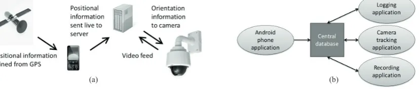
An agent piece of software (created in MicrosoftTM Visual Studio 2012, and written in VB.NET), was used to monitor the database for the positional information being fed back by the smartphone. The software then used the lookup table to obtain appropriate tilt values and calculates the pan values needed to get the pose of the PTZ camera to target the user/smartphone in the centre of the video stream. The required PTZ values were sent to the PTZ camera to move it to the required pose. The positional data was updated at 1 Hz; this speed was limited by the GPS chips in typical smartphones. For the purpose of this study the GPS location information was also logged every second. A schematic of the data flow in this system and the agent applications required is shown in Fig 2.
Fig. 2. (a) Schematic of the data flow in the tracking and recording system; (b) Agent applications required for tracking and recording of participants
3. Initial testing of the system
The agent software which estimated camera pose from a given location was tested by inputting a selection of grid coordinates and gauging how close the centre of view was from the selected coordinate. With all tested coordinates the software performed well, and directed the camera to centre of each location. To test the accuracy of the GPS tracking application and phone combination a small study was carried out at the Sheffield FieldLab. The
(a) (b)
(b)
Aerial view – pan angle Side view – tilt angle 0°
90°
ɲ
1ɲ
20°
180°
y
x
(0,0) local site origin
Camera location
[image:5.544.122.439.148.319.2] [image:5.544.63.477.445.534.2]AndroidTM application was installed on the three test smartphones (table 1) and run at the start of each test. The
application was left for approximately 30 seconds to allow a GPS lock to be established. The AndroidTM
application indicated this with a popup message on the screen, which displayed longitude and latitude coordinates. At this point a single participant was asked to hold the smartphone and walk around the FieldLab along a set route. The PTZ camera tracking software was also run at the same time and videos recorded of the walking path. The reported points from the GPS tracking application were logged, from the point at which the participant starting walking to the point at which they returned to the start of the path. The logged points were later compared to the coordinates of the walking path obtained by the same method used to find the location of the calibration points.
[image:6.544.50.494.244.438.2]4. Results
Fig. 3 shows the walked path compared to the reported location points of the AndroidTM application which was run
on the three test smartphones (note that linear fits were added to the reported GPS positions to visualise the reported paths). Table 2 shows the deviation from the reported location to the path walked and will be used as a comparison between different phones.
N
Fig. 3. The actual path walked against reported positions from the Android tracking application running on the: (a) Alcatel onetouch, (b) Motorola Defy mini and (c) Sony Xperia S
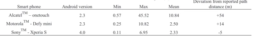
Table2. Deviation from the walked path of the reported location of the Android smartphones used within this study
Deviation from path (m)
Deviation from reported path distance (m) Smart phone Android version Min Max Mean
AlcatelTM – onetouch 2.3 0.57 45.52 10.84 +54
MotorolaTM - Defy mini 2.3 0.25 10.82 2.50 +14
SonyTM - Xperia S 4.0 0.11 6.95 2.33 -5
5. Discussion
Initial testing of the pose estimation software agent showed that with a selection of test grid points, the camera centred on the correct position. The live feed and recording element of this software worked well, centring on the reported position of the GPS smartphone in the initial tests.
[image:6.544.44.475.508.570.2]173 Leon Foster et al. / Procedia Engineering 72 ( 2014 ) 168 – 173
It was evident from reviewing the live feed that the camera did not always centre on the participant during the initial testing. This was not due to the PTZ pose estimation software, but rather by errors in the reported position of the smartphone. Fig. 3 shows visually the deviation from the walked path and the reported positions that were fed back from the AndroidTM application. Table 2 shows the maximum, minimum and average deviation. It is apparent
that the three smartphones tested in this study have very different GPS performance.
The AlcatelTM onetouch appears to be the worst performer, with a maximum deviation from the path of 45.52 m
and average deviation of 10.84 m. The SonyTM Xperia S was the best performer with a maximum deviation from the path of 6.95 m and an average of 2.33 m. As a measure of accuracy Coutts & Duffield (2010) and Edgecomb & Norton (2006) used the comparison of path distance calculated from the GPS coordinate to the actual distance travelled measured physically. In this study, the Defy mini and onetouch smartphones reported path distances of greater than the actual path length and the Xperia slightly lower. The Xperia S again appeared to perform the best with the least deviation from path length walked. The Defy mini and onetouch smartphones appear to report the greatest deviation from the walked path in the most southerly region of the site. These deviations account for the larger errors in reported path length from the Defy mini and onetouch. Environmental factors are a possible cause of this; due to a building in this area of the site GPS satellite signals could have been shielded/reflected. This means a positional fix could have been lost/wildly inaccurate. The Xperia S however, reported consistent positions in this section of the site. The mid-range Defy mini and high-end Xperia S reported an average deviation of around between 2.33 and 2.5 m from the path. These low deviation values means that the PTZ tracking software concept is plausible if these smartphones are used and the field of view is not too small. In theory the tracked target will always be within 2.5 metres of the centre of the camera view.
The main limitations of the current tracking and filming system were the update rates and accuracy of GPS positional data (update frequency of 1 Hz). In theory this means that for high speed movements and changes in direction, some positional data and resolution will be lost. The positional system could be improved by using other information such as accelerometer data and signal strength returned from a WIFI Access point. A faster updating GPS chipset of 5 - 10 Hz is another possibility, but these are rare and not currently standard in smartphones. An additional limitation was a lack of smoothing of the camera movement, meaning the camera moved abruptly to the required position. A method for smooth panning and tilting of the camera is the subject of further development.
6.Conclusion
In conclusion it is believed that the proposed system is a suitable way of visually tracking participants around a FieldLab, if a medium to high end smartphone is utilised. The system could be employed to collect movement and positional data of a user’s interaction with a newly introduced piece of interactive equipment in the FieldLab. This could demonstrate the equipment’s effectiveness. It is also envisaged that this system could be used to monitor individual football players on a pitch, creating a so called automatic “player cam”. This may be useful for training purposes, for example if coaches require analyses of different players’ movement. However, the limitation of a 1 Hz update rate and GPS accuracy could mean a machine vision tracking system is favorable in this situation.
References
Bajaj, R., Ranaweera, S. L., & Agrawal, D. P. 2002. GPS: location-tracking technology. Computer, 35(4), 92-94. Catapult 2013 [online]. Last accessed on 01/11/2013 at URL: http://www.catapultsports.com/
Coutts, A. J., & Duffield, R. 2010. Validity and reliability of GPS devices for measuring movement demands of team sports. Journal of Science and Medicine in Sport, 13(1), 133-135.
Edgecomb, S. J., & Norton, K. I. 2006. Comparison of global positioning and computer-based tracking systems for measuring player movement distance during Australian football. Journal of Science and Medicine in Sport, 9(1), 25-32.
Profit 2013. FieldLAB: An opportunity for internation cooperation in sports innovation [online]. Last accessed on 01/11/2013 at URL: http://www.fieldlabs.eu/
Google 2013. Get the Adnroid SDK [online]. Last access on 01/11/2013 at URL: http://developer.android.com/sdk/index.html
Hrabar, S., Corke, P., & Hilsenstein, V. 2011. PTZ camera pose estimation by tracking a 3D target. In: Robotics and Automation (ICRA), 2011 IEEE International Conference, pp. 240-247.