PI Control Based Vector Control Strategy for
Induction Motor Drive
Missula Jagath Vallabhai Department of Electrical Engineering
Maulana Azad National Institute of Technology, Bhopal, India
Pankaj SwarnkarDepartment of
Electrical Engineering Maulana Azad National Institute of Technology,
Bhopal, India [email protected]
D.M. DeshpandeDepartment of
Electrical Engineering Maulana Azad National Institute of Technology,
Bhopal, India [email protected]
Abstract — In this paper Proportional and Integral controller is applied to control the speed and flux of induction motor. The new control scheme is proposed which avoids the use of the Sensors to measure the speed. This paper develops a Field Oriented Control Scheme for an induction motor. Using
the field-oriented control, a highly coupled, nonlinear,
multivariable induction motor can be simply controlled through linear independent decoupled control of torque and flux, similar to separately excited dc motors. By providing decoupling of torque and flux control demand, the vector control can govern an induction motor drive similar to a separate excited dc motor without sacrificing the quality of the dynamic performance. The Speed and Stator flux errors are used to run the PI controller to generate required current and voltage referred to stator side for controlling the speed and flux of Induction motor. Simulation is done in MATLAB and SIMULINK and results are discussed in detail.
Key words — Field vector control, PI control, Sensorless control.
I. INTRODUCTION
Major improvements in modern industrial processes over the past 50 years can be largely attributed to advances in variable speed motor drives. With the advancement in power electronic devices and the advent of DSP technology fast, reliable and cost effective control of induction motors is now possible. The area of AC motor control has continued to expand because induction motors are excellent candidates for use in Electric or Hybrid Electric Vehicles. Over the past two decades a great deal of work has been done into techniques such as Field Oriented Control, Direct Torque Control and Space Vector Pulse Width Modulation. This paper thoroughly investigated the aforementioned techniques and used them to develop a Field Oriented Vector Control Scheme [9], [10] for controlling the rotor flux and speed control of induction motor. Variable-speed drives for induction motors require both wide operating range of speed and fast torque response, regardless of load variations. The field oriented control is the most successful in meeting the
range can be usefully applicable to minimum-time speed control of induction motors.
Field oriented control [11] method is widely used for advanced control of induction motor drives. However, the field oriented control of induction motor drives presents two main problems that have been providing quite a bit research interest in the last decade. The first one relies on the uncertainties in the machine models and load torque, and the second one is the precise computation of the motor speed without using speed sensors. The decoupling characteristics of the vector control are sensitive to machine parameters variations. Moreover, the machine load characteristics are not exactly known, and may vary during motor operations. Thus the dynamic characteristics of such systems are very complex and nonlinear. To overcome the above system uncertainties, the variable structure control strategy using adaptive control mode [12]-[16] has been focused on many studies and research for the control of the AC servo drive system in the past decades.
In last few decades modern PID control schemes [1]-[8] have been developed for improving the performance of variable speed drives. In this paper, a sensorless vector control scheme with PI controller is presented to improve the performance of a sensorless vector controller in a low speed region. Using the sensorless variable structure control to govern the induction motor drive, the rotor speed becomes insensitive to variations in the motor parameters and load disturbances. Moreover, the proposed control scheme provides a good transient response and exponential convergence of the speed trajectory tracking in spite of parameter uncertainties and load torque disturbances.
II. MATHEMATICAL
MODELING OF
INDUCTION
MOTOR
The three phase induction motor is first converted into corresponding two phase Kron’s model. The voltage equations of the three phase induction motor in synchronous rotating reference frame are:
above requirements. The objective of a variable-speed control system for higher productivity is to track the
Vqs
Vds
s= R siqs s= R
sids s+dΨ
qs s+dΨ
ds
s/dt (1)
s/dt (2)
reference speed as fast as possible. Therefore, under the constraints of input voltage and current, a control scheme which yields the maximum torque over the entire speed
Where,ΨqsandΨdsare q-axis and d-axis stator flux linkages
referred to the arbitrary reference frame. Ψdr s
= ΨrCosθe (18)
J is the moment of inertia and B is the coefficient of viscous Ψqrs= ΨrSinθe (19) friction. Teis the developed torque and TLis the load torque. Ψr=√[(Ψdrs)2+ (Ψqrs)2] (20) the general reference frame can be expressed by using the
transformations of the motor quantities from one reference frame to the general reference frame introduced. The Induction motor model is often used in vector control algorithms. The aim of vector control is to implement control schemes which produce high-dynamic performance and are similar to those used to control DC machines. To achieve this, the reference frames may be aligned with the stator flux-linkage space vector, the rotor flux-flux-linkage space vector or the magnetizing space vector. The most popular reference frame is the reference frame attached to the rotor flux linkage space vector with direct axis (d) and quadrature axis (q). After transformation into d-q coordinates the motor model follows:
These equations in de-qeframe are,
Vqs= Rsiqs+dΨqs/dt +ωeΨds (3)
Vds= Rsids+dΨds/dt -ωeΨqs (4)
Where, all the variables are in rotating form. The last term in Equations Vqsand Vdscan be defined as speed emf due to
rotation of the axes.ωeand ωrare the speed of the reference
frame and the mechanical speed of the rotor in rad/sec. Rs
and Rr are the stator and rotor resistances per phase of the
motor respectively.
Ifωe = 0, the equations are changed in to stationary form.
Note that the flux linkage in the de and qeaxes induces emf in the qe and de axes respectively, withΠ/2 lead angle. If the rotor is not moving, i.e., ωr = 0, the rotor equations for a
doubly-fed wound-rotor machine will be similar to above two Equations.
Vdr= Rridr+d Ψdr/dt -ωe*Ψqr (5)
Vqr= Rriqr+d Ψqr/dt +ωe*Ψdr (6)
Here, all the variables and parameters are referred to the stator. Since the rotor moves at a speedωe-ωrrelative to the
synchronously rotating frame, therefore, in de - qe frame, the rotor equations are modified as,
Vdr= Rsidr+d Ψdr/dt-(ωe-ωr)Ψqr (7)
Vqr= Rriqr+d Ψqr/dt+ (ωe-ωr)Ψdr (8)
The Electromagnetic Torque is given by
The voltages on the ds-qsaxes can be converted in to the de -qeframe as follows.
Vqs=Vqsscosθe-Vdsssinθe (12)
Vds=Vqsssinθe+Vdsscosθe (13)
Resolving rotating parameters in to stationary parameters, in to a stationary frame, the relations are,
Vqss = Vqscosθe+Vdssinθe (14)
Vdss = -Vqssinθe+Vdscosθe (15)
IV. LOAD
TORQUE
DISTURBANCE
(T
L)
COMPENSATION
When a sudden load or disturbance torque TLcan cause a
droop in the speed in a speed-controlled drive system, which may not be desirable. The speed droop can be compensated with the help of a disturbance torque observer. The speed and torque are given by the following relation
Jdωm/dt+ Bωm= Te-TL (16)
Where, B = viscous friction coefficient. Therefore, TL can
be estimated by the following equation:
TL= Te–(JS+B)ωm (17)
The actual speed ωm is measured with the measurement
delay time Td. The signal is processed through the inverse
mechanical model (JS + B) and then subtracted from the effective torque Te' to generate the estimated torque signal.
V. VECTOR
CONTROL OF
INDUCTION
MOTOR
Field angle is calculated by using terminal voltages and currents. The control parameters ids and iqs which are dc
values in synchronously rotating reference frame converted to stationary frame by using unit vectors generated from flux vector signalsΨdr and Ψqr. These flux signals are generated
from the machine terminal voltages and currents with the help of the voltage model estimator. For precision control of flux, control loop should be added. The torque component of current iqs is generated from the speed control loop through
iqs aligning of current idsin the direction of fluxΨr and the
Te=3P (Ψdsiqs-Ψqsids)/2 (9) current iqs perpendicular to it is de – qe will rotate at
The torque balance equation is:
J*dωr/dt= Te-TL-Bωr (10)
Where, (5), (6), (7), (8) are all voltages and currents are
synchronous speed (ωe) with respect to stationery frame ds–
qs. The angular position of the de axis with respect to the ds axis isθe.
Te= 3PLm(Ψdriqs-Ψqrids) /2Lr (11) Ψrvector is represented by magnitudeΨr. This unit vector
signal, when used for vector rotation, gives currents idson de e
III. 2R-2S TRANSFORMATION
axis and iqson q axis. WhenΨqr= 0 andΨdr=Ψr, then theThe synchronously rotating de-qe axes rotates at synchronous speedωe with respect to the ds-qsaxes and the
angleθe=ωe*t. The two phase ds-qswindings are transformed
in to the hypothetical windings mounted on the de-qe axes.
R
O
T
O
R
T
O
R
Q
U
E
[N
-m
]
R
O
T
O
R
S
P
E
E
D
[r
a
d
/s
e
c
]15
10 applications requiring high dynamic performances like a
separately excited DC motors.
VI. ESTIMATION OF SPEED
The speed of the motor is estimated by estimating the synchronous speed and subtracting the command slip speed. The synchronous speed is estimated using the stator flux components, because of its higher accuracy compared to estimation based on rotor flux components. The rotor speed of an induction motor is expressed in terms of synchronous and slip (angular) frequencies is as follows
ωr= (ωe-ωsl)/p (21)
The estimation of rotor speed is accomplished by an estimation of either synchronous, or slip frequency, with the other being known. In the proposed speed estimation scheme, the synchronous frequency is estimated and slip frequency is assumed as command. So the estimated rotor
the loop gain constant as well as reduce the cross over frequency. Whereas reducing kpwill only decrease the cross
over frequency with a constant gain. In this paper the vector controlled induction motor is attached with a PI controller for improving the steady state characteristics in term of speed and flux.
VIII. SIMULATION
RESULTS
The model for vector control Induction motor with PI controller using vector control scheme is simulated in MATLAB.
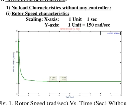
I. NOLOADCHARACTERISTICS:
1) No load Characteristics without any controller: (i) Rotor Speed characteristic:
Scaling: X-axis: 1 Unit = 1 sec Y-axis: 1 Unit = 150 rad/sec
ROTOR S P E E D VS . TIME
25 speed of the sensorless drive is obtained from the above
equation as: 20
ωr= (ωe-ω*sl)/p (22)
Where,
ωr = estimated rotor frequency in rad/sec.
ROTOR S P E E D
ω*sl = command value of slip frequency in rad/sec.
The estimated synchronous frequency is derived based on 0 the rotor flux model, or the stator flux model. -5
X: 2.98 9 Y : 1.0 4 9
X: 3.98 4 Y : 1.0 1 8
The stator resistance can be measured fairly accurately. Hence, stator flux can be estimated more accurately compared to the rotor flux. Therefore the estimated stator flux can be used to derive the synchronous frequency.
0 1 2 3 4 5 6 7 8 9 10
TIME [s ec]
Fig. 1. Rotor Speed (rad/sec) Vs. Time (Sec) Without any Controller
(ii) Rotor Torque characteristic:
E LE CTRO M A G NE TIC TO RQ UE V S . TIM E
VII. INDUCTION
MOTOR
WITH PI
CONTROLLER
In a PI controlled drive, the tuning of the proportional and integral gains of a simulated or experimental system can be done in the past, several commercial auto tuned PID controllers for general purpose and higher order linear controlled systems were available. In this paper, simulation diagram of vector controlled drive system where the PI controller gains kpand kiare being tuned in the speed control
loop. The expert controller contains the knowledge base for
0 .0 4
0 .0 2
0
-0. 0 2
-0. 0 4
-0. 0 6
-0. 0 8
-0. 1
TO RQ UE
0 1 2 3 4 5 6 7 8 9 1 0
TIM E [s ec ]
tuning the controller. It is assumed that initially, the PI parameters will be loaded such that the system will remain within the stability limit. The initial parameters can be derived from the knowledge of the plant parameters. A square wave auxiliary test signal is injected as the speed command ωr* and the pattern of the error response e is
retrieved. From the knowledge base, the controller can look in to the error response and determine how the kp and ki
parameters are to be modified to get the correct tuning. Since, kp+ (ki/s) = ki/s (1+s/k) where, k=ki/ kp. It is evident
that the second order drive system, reducing ki will reduce
Fig. 2. Electro Magnetic Torque [Te] (N-m) Vs. Time (Sec) Without any Controller
R
O
T
O
R
S
P
E
E
D
[r
a
d
/
s
e
c
]
R
O
T
O
R
T
O
R
Q
U
E
R
O
T
O
R
F
L
U
X
[w
b
]
R
O
T
O
R
F
L
U
X
[w
b
]
L
O
A
D
T
O
R
Q
U
E
[N
-m
]
0.5 0.45 0.4 0.35
X: 3.229 Y: 0.4517
ROTOR FLUX
1 0.9 0.8 0.7
X: 0.8342 Y: 0.9921
ROTOR FLUX VS. TIME
0.3 0.25 0.2 0.15 0.1 0.05
0.6 0.5 0.4 0.3 0.2
0
0 1 2 3 4 5 6 7 8 9 10 TIME [Sec]
0.1 0
Fig. 3. Rotor Flux (wb) Vs. Time (Sec) without any Controller
2) No load Characteristics with PI Controller (i) Rotor Speed characteristic:
Scaling: X-axis: 1 Unit = 1 sec Y-axis: 1 Unit = 150 rad/sec
0 1 2 3 4 5 6 7 8 9 10 TIME[Sec]
Fig. 6. Rotor Flux (wb) Vs. Time (Sec) with PI Controller
(iv) d-axis and q-axis flux with reference to the stator side
1 . 5 1 0 . 5 0 - 0 . 5
X : 0 . 5 2 8 9 Y : 1 . 6 1 1
X : 1 . 1 2 9 Y : 1 . 0 3 1
X : 0 . 5 0 1 8 Y : 0 . 0 2 2 7 1
R O T O R S P E E D V S . T IM E
R O T O R S P E E D V S . T IM E
- 1 - 1 . 5 - 2
0 1 2 3 4 5 6 7 8 9 1 0 T IM E [ S e c ]
Fig. 4. Rotor Speed (rad/sec) Vs. Time with PI Controller
Fig. 7. d-axis flux with Reference to Stator Side Using
PI Controller
(ii) Rotor Torque characteristic:
X : 0 .3 4 8 3 Y : 1 9 .1 7
2 0 1 5 1 0
R O T O R T O R Q U E V S . T IM E
R O T O R T O R Q U E V S . T IM E
5 0 - 5 -1 0 -1 5 -2 0 -2 5
X : 1 Y : 0 .0 0 3 5 5 6
X : 4 .7 4 6 Y : 0 .0 0 1 0 7 1
X : 7 .7 1 5
Y : - 0 .0 1 5 7 9 Fig. 8. q-axis Flux with Reference to Stator Side Using PI
Controller
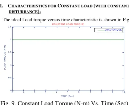
II. CHARACTERISTICS FORCONSTANT LOAD[WITH CONSTANT
DISTURBANCE]:
The ideal Load torque versus time characteristic is shown in Fig 9.
CO N S TA NT LO A D TO RQ UE
2.5
LO A DTO RQ U E
0 1 2 3 4 5 6 7 8 9 1 0 T IM E
Fig. 5. Electromagnetic Torque (Te) (N-m) Vs. Time (Sec)
With PI Controller
2 1.5 1 0.5 0
0 1 2 3 4 5 6 7 8 9 10 TIM E [ S ec ]
Fig. 9. Constant Load Torque (N-m) Vs. Time (Sec)
R O T O R S P E E D [r a d /s e c ] R O T O R F L U X [w b ] E L E C T R O M A G N E T IC T O R Q U E [N -m ] R O T O R S P E E D [r a d /s e c ] R O T O R F L U X [w b ] R O T O R T O R Q U E
(i) Rotor Speed characteristic: (ii) Rotor Torque characteristic:
4
3.5
4
x 10
Y-axis: 1 Unit = 150 rad/sec
ROTOR SPEED VS. TIME
ROTOR SPEED
25 20
X: 0.001837
15
Y : 17.97
ROTOR TORQUE VS. TIME
3 10
2.5 5 X: 1.03
Y : 1.998 X: 2.117 Y : 2
X: 4.867 Y : 2
2 0
1.5 -5
-10
0.5
0
TIME [ Sec ]
-15 -20
0 1 2 3 4 5 6
TIM E
Fig. 10. Rotor Speed (rad/sec) Vs. Time Without any Controller
(ii) Rotor Torque characteristic:
ELECTRO MAGNETIC TORQUE VS . TIME
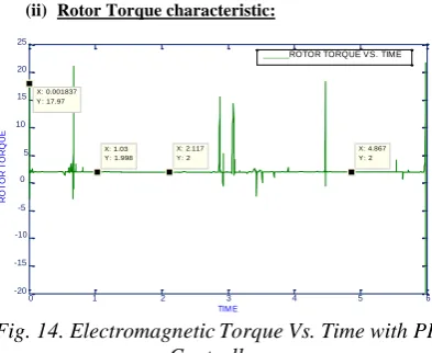
Fig. 14. Electromagnetic Torque Vs. Time with PI Controller
(iii) Rotor Flux characteristic:
20 ROTOR TORQUE 15 10 1 0.9 0.8
ROTOR FLUX VS . TIM E
ROT FLUX 5 0.7 0 0.6 0.5 -5 -10 0.4 0.3 -15
0 0.5 1 1.5 2 2.5 3 3.5 4
TIME[Sec ]
0.2 0.1
Fig. 11. Electro Magnetic Torque Vs. Time Without any Controller
0
0 1 2 3 4 5 6 TIME [ Sec ]
(iii) Rotor Flux characteristic:
R O TO R F L U X V s . TIM E
R O TO R F L U X
Fig.15. Rotor Flux Vs. Time with PI Controller
(iv) d-axis and q-axis flux with reference to the stator side
0 . 3 5
0 . 3
0 . 2 5
0 . 2
0 . 1 5
0 . 1
0 . 0 5
0
0 1 2 3 4 5 6 7 8 9 1 0
T IM E [ S e c ]
Fig. 12. Rotor Flux Vs. Time Without any Controller
2) Constant load characteristic with PI Controller: (i) Rotor Speed characteristic:
Scaling: X-axis: 1 Unit = 1 sec Y-axis: 1 Unit = 150 rad/sec
ROTOR SPEED VS. TIME
Fig. 16. d-axis Flux with Reference to Stator Side Ising PI Controller 3 2 1.5 1 0.5 0 X: 0.04921 Y: 2.966 X: 0.6037 Y: 1.608 X: 0.5 Y: -0.1643 X: 1.788 Y: 0.978
ROTOR SPEED VS. TIME
-0.5 -1
0 1 2 3 4 5 6 7 8 9 10 Fig. 17. q-axis Flux with Reference to Stator Side Using PI TIME [Sec]
L O A D T O R Q U E E L E C T R O M A G N E T IC T O R Q U E [N -m ] R O T O R S P E E D [r a d /s e c ] L O A D T O R Q U E [N -m ] O U T P U T T O R Q U E R O T O R S P E E D [r a d /s e c ] R O T O R F L U X [w b ] R O T O R F L U X [w b ]
III. CHARACTERISTICS OFVARIABLE LOAD[WITHVARYING
DISTURBANCE]:
(iii) Rotor Flux characteristic:
0 . 1 4
R O T O R F L U X V S . T IM E
The Load torque versus time characteristic is shown in Fig 18.
V A R Y IN G L O A D T O R Q U E V S . T IM E 5
0 . 1 2 0 . 1
4 . 5
4
0 . 0 8
3 . 5 0 . 0 6
3
2 . 5
0 . 0 4
2 0 . 0 2
1 . 5
1
0 . 5
0
0 0 . 5 1 1 . 5 2 2 . 5 3 3 . 5 T IM E [ s e c ]
0
0 1 2 3 4 5 6 7 8 9 1 0
T IM E [ S e c ]
Fig.18. Varying Load Torque Vs. Time
1) Without any Controller
Fig.21. Rotor Flux Vs. Time Without any Controller
2) Variable load characteristic with PI Controller: (i) Rotor Speed characteristic:
Scaling: X-axis: 1 Unit = 1 sec Y-axis: 1 Unit = 150 rad/sec
ROTOR SPEED VS. TIME
(i) Rotor Speed characteristic:
Scaling: X-axis: 1 Unit = 1 sec Y-axis: 1 Unit = 150 rad/sec
6 5 X: 0.00515
Y: 5.507
ROTOR SPEED VS. TIME
3 . 5 3
4
x 1 0 R O TO R S P E E D V S . TIM E
R O TO R S P E E D
4 3 X: 0.5311
Y: 2.38
2 . 5 2 1 . 5 1
2 1
X: 0.5003
0 Y: -0.3014 X: 1.959 Y: 0.9831
X: 3.306 Y: 1.024
0 . 5 0
-1
0 1 2 3 4 5 6 7 8 9 10 TIME [Sec]
-0 . 5
0 0 .5 1 1 .5 2 2 .5 3 3 . 5 TIM E [ s ec ]
Fig.22. Varying Load Rotor Speed (rad/sec) Vs. Time
(Sec) with PI Controller
Fig.19. Rotor Speed Vs. Time without any Controller for
Varying Load (ii) Rotor Torque characteristic:
O U T P U T T O R Q U E V S . T IM E
6 (ii) Rotor Torque characteristic:
5
E L E C TR O M A G N E TIC TO R Q U E V S . TIM E
O U T P U T T O R Q U E V S . T IM E
20
E L E C TR O M A G N E TIC TO R Q U E V S . TIM E 4
15 3 10 2 5 1 0 0 - 1 -5 -10 -2
0 1 2 3 4 5 6 7 8 9 1 0
T IM E
-15
0 0.5 1 1.5 2 2.5 3 3.5
Fig.23. Electro Magnetic Torque (T
e) in N-m Vs.
TIM E [s ec ]
Fig.20. Electro Magnetic Torque Vs. Time Without
any Controller
Time (Sec) with PI Controller
(iii)Rotor Flux characteristic:
R O TO R F L U X V S . TIM E
1
0 . 9
R O T F L U X
0 . 8
0 . 7
0 . 6
0 . 5
0 . 4
0 . 3
0 . 2
0 . 1
0
0 1 2 3 4 5 6
TIM E [ S e c ]
(iv)d-axis and q-axis flux with reference to the stator side
Fig.25. d-axis Flux with Reference to Stator Side
Using PI Controller
Fig.26. q-axis Flux with Reference to Stator Side Using PI
Controller
IX. CONCLUSION
Comprehensive study on dynamic d-q model and vector control has been made. To study the dynamic performance of an induction motor, MATLAB SIMULINK toolbox is used. It is observed that during transients, the Induction motor without any controller becomes unstable. Its dynamic characteristics are improved with the application of PI controller Tables I and II give the comparison of Induction motor performance without any controller and with PI controller. This comparison is carried out for different loading conditions. Firstly the motor is at no load condition then it is loaded with constant load and finally it is loaded with variable load. Under these conditions the speed and flux of induction motor are calculated and their characteristics are shown in Fig.s. The specifications which are taken for the comparison are maximum Overshoot, settling time, steady state value and steady state error. From the simulation results, it can be concluded that the performance of Induction motor is improved drastically with the application of PI controller for field oriented Induction motor drive. It is most capable scheme for reducing the spikes, maximum overshoot, and Steady state error.
TABLES
I. COMPARATIVE ANALYSIS OF INDUCTION MOTOR PERFORMANCE FOR SPEED AS A PARAMETER
WITHOUT ANY CONTROLLER PI CONTROLLER
Description No Load Constant Load Variable Load No Load Constant Load Variable Load
% Max. Overshoot 20.5 Unstable Unstable 0.611 1.966 4.507
Settling Time (Sec) 3.984 Unstable Unstable 1.121 1.788 3.306
Steady State Speed 1.018 Unstable Unstable 1.031 0.978 1.024
Steady State Error -0.018 Unstable Unstable -0.031 0.022 -0.024
WITHOUT ANY CONTROLLER PI CONTROLLER
Description No Load Constant Load Variable Load No Load Constant Load Variable Load
% Max. Overshoot 0 Unstable Unstable 0 0 0
Settling Time (Sec) 3.229 Unstable Unstable 0.8342 0.98 0.982
Steady State Flux 0.4517 Unstable Unstable 0.9921 0.982 0.983
Steady State Error 0.5483 Unstable Unstable 0.0097 0.018 0.017
REFERENCES
[1] Rey-Chue Hwang, Huang-Chu Huang, Wei-Shen Chi, “ANew Fuzzy PID-Like Controller”, IEEE international conference on systems, man, cybernetics, vol. 5, 2000.
[2] K. S. Tang, Kim Fung Man, Guanrong Chen, Sam Kwong,“An Optimal Fuzzy PID Controller”, IEEE Transactions on industrial electronics, vol. 48, No. 4, August 2001.
[3] K.L. Lo and M.O. Sadegh,“Systematic method for the design of a full-scale fuzzy PID stability controller for svc to control power system”, IEEE transaction on generation transmission and distribution Vol. 150, 2003.
[4] Baozhu Jia, Guang Ren and Gang Long,“Design and Stability Analysis of Fuzzy Switching PID Controller”, 6th World Congress on Intelligent Control and Automation, June 21 - 23, 2006, Dalian, China.
[5] Ahmed Rubaai, Marcel J. Castro-Sitiriche, Abdul Ofoli,“ DSP-Based Implementation of Fuzzy-PID Controller Using Genetic optimization for High Performance Motor Drives”, IEEE international conference on industry applications, 2007.
[6] Ahmed Rubaai, Marcel J. Castro-Sitiriche, and Abdul R. Ofoli, “DSP-Based Laboratory Implementation of Hybrid Fuzzy-PID Controller Using Genetic Optimization for High-Performance Motor Drives”, IEEE Transactions on industry applications, vol. 44, No. 6, November/December 2008.
[7] Dan Sun, Jun Meng, “A Single Neuron PID Controller Based PMSM DTC Drive System Fed by Fault Tolerant 4-Switch 3-Phase Inverter”, IEEE international conference on industrial electronics and applications, 2006.
[8] Jianjun Yao , Liquan Wang ,Caidong Wang, Zhonglin Zhang and Peng Jia, “ANN-based PID Controller for an Electro-hydraulic Servo System”, IEEE International Conference on Automation and Logistics Qingdao, China September 2008.
[9] Z. S. Wang, S. L. Ho, “Indirect Vector Control for Induction Motors in Absence of current Sensors” IEEE Transactions on Industrial Applications, vol-20, No.1 , Jun-2006.
[10] J.W.L. Nerys, “Alternative Implementation of vector control of Induction Motors”, IEE-Proc-Power Applications, vol -147, No-1, Jan-2000.
[11] Jung-Ik Ha, “Sensorless Field Orientation control of Induction Motors”, IEEE- Transactions on Industrial Applications, vol-35, No.1, Jan 1999.
[12] C.C. Chan, W. S. Leung, “Adaptive decoupling control of induction motor drives”, IEEE Transactions on industrial electronics, vol. 31, no. 1, February 1990.
[13] Maurizio Cirrincione, Marcello Pucci, “An MRAS-based sensorless high performance induction motor drive with a predictive adaptive model”, IEEE transaction on industrial electronics, vol. 52, No. 2, April 2005.
[14] Pankaj Swarnkar, Shailendra Jain, R.K.Nema, “Effect of adaptation gain on system performance for Model reference adaptive control scheme using MIT rule”, International conference of World Academy of science, engineering and technology, Paris, France, October 27-29, 2010.
[15] Pankaj Swarnkar, Shailendra Jain, R.K.Nema, “Application of Model reference adaptive control scheme to second order system using MIT rule”, International conference on Electrical Power and Energy Systems, August, 26-28, 2010, MANIT, Bhopal, India.
[16] Teresa Orlowska-Kowalska, Krzysztof, “Control of the drive system with stiff and elastic coupling using adptive neuro-fuzzy approach”IEEE transaction on industrial electronics, vol. 54, No. 1, February 2007.
AUTHOR
’
SPROFILE
Missula Jagath Vallabhai
received the B.Tech degree in Electrical and Electronics engineering from JNTU, Hyderabad, India in 2008 and the M.Tech degree in Electrical drives from Maulana Azad National Institute of Technology, Bhopal, India in 2010. He is working as a Project Associate in IIT
Hyderabad and doing Research on Design of Solar and Wind Hybrid Power System. His field of interest includes Control System, Network Analysis, Power System and Electrical Drives.
Pankaj Swarnkar
received the B.E. degree from Govt. Engineering College, Jabalpur, India in 1998 and the M.Tech degree from Maulana Azad National Institute of Technology, Bhopal, India in 2004. Currently he is Assistant
Professor in Maulana Azad National Institute of Technology, Bhopal and pursuing the Ph.D. degree. His field of interest includes Control System, Network Analysis and Power System.
D.M. Deshpande
received the B.E. degree in 1970, the M.E. degree in 1972 from VRCE, Nagpur India and the Ph.D. degree from Barkatullah University, Bhopal, India in 2002. Currently he is Professor in the Department of Electrical Engineering, National Institute of Technology, Bhopal,