Study of Methods to Mitigate Fading in Mobile
Communication
Parul Varshney
Department of ECE, Shobhit University, Meerut, India
Anubhav Tiwari
Asstt. Proff. Deptt. Of ECE, Shobhit University,Meerut, India [email protected]
Abstract
—
"Due to communication world has become a smaller place to live in, according to this we can leap 3G to 4G along its features and future trends i n mobile technology. But the biggest challenge faced by designers of wireless communication systems is the variations in the wireless channel which arise mainly due to the phenomenon of multipath fading which is inevitable in scattering environments that are subject to changes over time. A wide variety of pre/post processing techniques have been used to mitigate the degrading effects of such channels, but with limited improvements in performance. This paper provides an evaluation of the concept of Spatial Diversity (SD), applied to multi-antenna systems that demand modifications at the physical level - the use of multiple antennas at the transmitter and/or the receiver. The performance of SISO, SIMO, MISO and MIMO systems have been evaluated and compared in AWGN and fading channels.Keywords
—
Communication, MIMO, Multi antenna Systems, Spatial diversityI.
I
NTRODUCTIONThe mobile communication channel is susceptible to multipath fades due to a large number of scaterers and reflectors. Diversity techniques are used to mitigate the effects of the multipath phenomenon. For a communication system to exhibit acceptable performance, a certain minimum signal level is needed at the receiver. When the signal level is less than this minimum threshold, the system is i n a fade. Typically, this phenomenon is described as the constructive / destructive interference between signals arriving at the same antenna via different paths, and hence, with different delays and phases, resulting in random fluctuations of the signal level at the receiver. Deep-fades that may occur at a particular point in space, or at a particular time or frequency, result in severe degradation of the quality of signals at the receiver making it impossible to detect and decode. Several mathematical models have been developed to describe such channels, taking into account, the phenomenon of multipath fading and correlation between sub-channels. Common models employ Rayleigh, Rice and Nakagami-m distributions to approximate actual channel conditions and are described in [1],[2],[3]. The concept of diversity, that is, providing the receiver with multiple copies of the same message, is widely known to be effective in combating channel impairment arising due to multipath fading [3],[4]. This paper discusses the application of Spatial Diversity (SD) techniques to multi antenna wireless communication systems as in the case of Single Input - Multiple Output (SIMO), Multiple Input – Single Output (MISO) and
Multiple Input – Multiple Output (MIMO) systems. Spatial Diversity techniques are discussed in Section 2, in the context of SIMO, MISO and MIMO systems, with attention given to two combining techniques at the receiver: Maximal Ratio (MRC) and Equal Gain Combining (EGC). The assumed channel models are discussed in Section 3. The details of simulations and results are presented in Sections 4 and 5, and the conclusions are discussed in Section 6.
II.
S
PATIALD
IVERSITYSpace diversity, also known as Antenna diversity, is any one of several wireless diversity schemes that uses two or more antennas to improve the quality and reliability of a wireless link. Often, especially in urban and indoor environments, there is no clear line-of-sight (LOS) between transmitter and receiver. Instead the signal is reflected along multiple paths before finally being received. Each of these bounces can introduce phase shifts, time delays, attenuations, and distortions that can destructively interfere with one another at the aperture of the receiving antenna.
Antenna diversity is especially effective at mitigating these multipath situations. This is because multiple antennas offer a receiver several observations of the same signal. Each antenna will experience a different interference environment. Thus, if one antenna is experiencing a deep fade, it is likely that another has a sufficient signal. Collectively such a system can provide a robust link. The use of time and frequency diversity techniques requires extra temporal and spectral resources to ensure that the copies of the signal are sent through different channel conditions or paths. This situation can be avoided by using the additional dimension of space. Most wireless propagation media are rich scattering in nature, thereby introducing a limited degree of orthogonality between channel elements. This property of channels can be exploited using SD to transmit copies of signals via multiple paths to the receiver. Some amount of pre-processing or post pre-processing may be required at the transmitter and receiver, respectively, to enable the receiver to effectively combine the copies, or select the best copy, to maximize the Signal-to-Noise Ratio (SNR) at the output.
A.
SISO
Copyright © 2012 IJECCE, All right reserved Nevertheless, this case is included to assess its
performance in fading channels and to bring out the clear advantage of spatial diversity schemes that employ multiple antennas.
The system is simulated as follows:
r= h × c + n (1)
Where, r denotes the received symbol, h denotes the channel between the transmitter and receiver antennas and n denotes an AWGN component.
Fig.1. Block diagram of a SISO System
By Shannon‘s capacity theorem, the capacity per unit bandwidth of such a system is [5]
CSS = log 2 ( 1 + ρ |h|2 ) b s-1 Hz-1 (2)
where, ρ is the average SNR of the signal at the receiver and h is the normalized complex gain of the channel. B.
SIMO
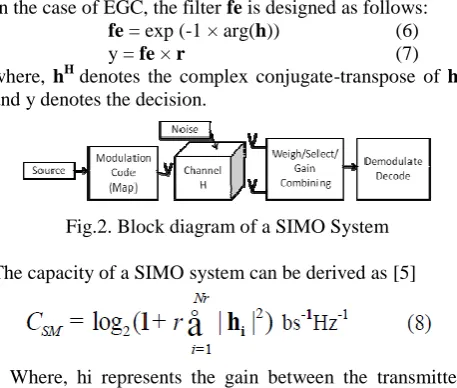
SIMO communication-systems utilize one antenna at the transmitter and multiple antennas at the receiver, Fig. 2. Thus, any signal transmitted from the single transmit-antenna will arrive at all receiver transmit-antennas through different sub-channels. It is assumed that each sub-channel, and hence, each channel element is completely decorrelated. As multiple independent copies of the same signal arrive at the receiver, it is possible to exploit the concept of spatial diversity, in this case receiver diversity. Assuming that perfect channel information is available at the receiver, it is possible to use combining techniques at the receiver based on the channel state information. Two combining techniques are used here: Maximal Ratio Combining (MRC) and Equal Gain Combining (EGC). Both these techniques involve the use of a matched filter at the receiver to optimally combine the received signals (at each antenna) to maximize the SNR at the output. Consider a 1 × Nr system, where Nr denotes the number of receiver antennas. The transmission of the message symbol c (after modulation) through a fading channel is simulated as follows:
r= h× c + n (3)
Where, r denotes the received vector of dimensions Nr × 1, h denotes the channel matrix of dimensions Nr × 1, each element giving the complex gain between the transmitter and each receiver; n denotes an additive noise vector of dimensions Nr × 1; c denotes a transmitted symbol. At the receiver, a matched filter is applied to combine the individual received signals.
In the case of MRC, the filter ‗fm‘ is designed as follows:
fm = hH (4)
y = fm × r (5)
where, hH denotes the complex conjugate-transpose of h, and y denotes the decision.
In the case of EGC, the filter fe is designed as follows: fe = exp (-1 × arg(h)) (6)
y = fe × r (7)
where, hH denotes the complex conjugate-transpose of h, and y denotes the decision.
Fig.2. Block diagram of a SIMO System
The capacity of a SIMO system can be derived as [5]
Where, hi represents the gain between the transmitter antenna and the it receiver antenna. Since the channel energy is combined coherently at the receiver, there is a significant array gain. The capacity increases logarithmically with the number of receiver antennas.
C.
MISO
MISO communication-systems utilize multiple antennas (Nt) at the transmitter and a single antenna at the receiver, Fig. 3. Assuming that perfect channel knowledge is available at the transmitter, it is possible to achieve transmit-diversity using MRC and EGC at the transmitter. Applying MRC at the transmitter, also known as beamforming, requires the use of a filter fm defined as
fm = (hH ) / ||h|| (9)
Where, h denotes a 1 × Nt channel vector. This filter is applied to the symbol to be transmitted, c; s = fm × c. The filtered symbol, when transmitted through all antennas travels to the single receiver antenna. The combining takes place as the copies travel through different sub-channels as follows:
y = h × s + n (10)
Where, n denotes an additive noise variable. Applying EGC requires the same operation in (10),
using a different filter
fe = exp (-1 × arg (h)) (11) If the total transmit power is fixed and equally divided amongst all antennas, the capacity of a MISO system can be derived as [5]
Fig.3. Block diagram of a MISO System
D.
MIMO
MIMO systems utilize multiple antennas at both the transmitter and receiver, Fig. 4. The most common form of diversity employed in MIMO systems is the space – time diversity, exploiting both space and time diversity. The Alamouti space time block code [5] is the simplest of the family of orthogonal space time codes. The capacity of MIMO systems is expressed as
Along with diversity, MIMO also provides multiplexing capabilities: allowing users to transmit different symbols from different transmit antennas, thereby improving the throughput of the system.
III.
C
HANNELM
ODELSA.
Additive White Gaussian Noise (AWGN) Channel
The simulated linear AWGN channel has a bandwidth greater than that of the message signal. The noise n is a complex Gaussian-distributed stationary random process with zero mean and is generated as a vector with the same number of elements as the message to be transmitted:n = <noise_power> × ( N(0,1) + i × N(0,1) ) (14) where N (0,1) is a vector of the same length as the message signal consisting of normal (Gaussian) random variables. The noise power is calculated as noise_power = (signal power)/SNR. This noise is added to the message vector c to obtain the received signal r.
r = c + n (15) B.
Rayleigh Flat Fading Channel
The Rayleigh flat fading channel is commonly used to describe multipath fading channels when there is no Line-Of-Sight (LOS) component, the number of independent copies (multipath) of the signal arriving at the receiver is large, and the coherence bandwidth of the channel is greater than the bandwidth of the signal itself. It can be shown by central limit theorem that such a channel, where each arriving signal is of approximately equal energy, can be modeled as a zero mean circularly symmetric complex Gaussian random variable h = i.i.d. CN(0,1). The envelope of this fading channel can then be modeled using a Rayleigh distribution. For the purpose of simulation, a single channel is generated as follows:
h = μ + σ × ( N(0,1) + i × N(0,1) ) (16) Where, μ is the mean of the random variable (assumed to be zero), σ is the standard deviation of the random variable (assumed as one or 0.707) and N(0,1) denotes a Normal (Gaussian) distributed random variable with zero-mean and unit-variance. The channel is assumed to be slow-fading, with variations occurring at intervals equal to the symbol duration.
C.
Ricean Flat Fading Channel
The Ricean flat fading channel is used to describe multipath fading channels that consist of a large number of multipath components and a strong LOS component. The Ricean K-factor is used to specify the power in the LOS component to the power in the scattered components. The
Ricean cannel is modeled using non-zero mean circularly symmetric complex Gaussian random variables as follows:
h = μ + σ × ( N(0,1) + i × N(0,1) ) (17) where, μ is the mean of the random variable (nonzero value), which is a contribution of the LOS component, σ is the standard deviation of the random variable, and N(0,1) denotes a Normal (Gaussian) distributed random variable with zero mean and unit-variance.
IV.
S
IMULATIONSMonte-Carlo simulations were carried out to analyze the performance of each of the mentioned multi-antenna configurations. MRC and EGC schemes were used to obtain the output at the receiver in SIMO and MISO systems. The performance was measured by plotting the average Symbol/Bit Error Ratio (SER or BER) over a range of SNR values. The simulations were repeated for Rayleigh and Ricean fading channels. The digital data was modulated using Binary Phase Shift Keying (BPSK). The performance of the SISO configuration was evaluated to demonstrate the impact of fading on system performance. For evaluating the MIMO system, the concept of space time diversity was applied to a 2 × 1 and 2 × 2 case. A matched filter was applied at the receiver to retrieve the data.
V.
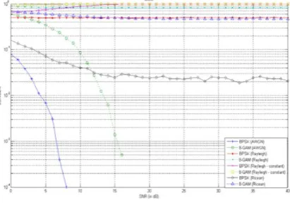
R
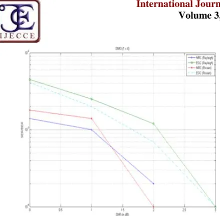
ESULTSFig. 5 shows the simulation results for a SISO system. It is clearly seen that the performance of SISO system in a fading channel is very poor compared to that of an AWGN channel, even for higher values of SNR. The destructive interference between multipath signals at the receiver results in severe degradation. It is noted that the performance in a Ricean channel slightly better than that in a Rayleigh fading channel. This is due to the strong LOS component present in the former case. Fig. 6 and 7 show the results of simulations of 1 × 4 and 1 × 2 SIMO systems. The availability of multiple copies of the same signal at the receiver enables the receiver to effectively combine theses multipath components, resulting in diversity gain at the receiver. Clearly, MRC provides a better performance when compared with EGC. This is due to the optimal nature of MRC, which maximizes SNR at the output.
Copyright © 2012 IJECCE, All right reserved Fig.6. Error Plots for SIMO (1 × 4) configuration
Fig.7. Error Plots for SIMO (1 × 2) configuration
A comparison of the results in Fig. 6 and Fig. 7 show that there is a significant improvement in system-performance (by the reduction of BER) as the number of receiver antennas are increased. This is clearly because of the increase in the number of copies of the signal provided to the receiver.
Fig. 8 shows the result of simulation of a 4 × 1 MISO system. Here, EGC shows slightly better results when compared with MRC. Also, the performances in Rayleigh and Ricean channels are quite similar. Again, it can be noted that there is a definite improvement in performance (reduction in BER) as the number of transmit-antennas are increased. Fig. 9 shows the result of the simulations of MIMO system. Space time block codes were employed to exploit both space and time diversity.
Fig.8. Error plots for MISO (4 × 1) configuration
Fig.9. Error plot for a 2 × 1 and 2 × 2 system
VI.
C
ONCLUSIONSR
EFERENCES[1] M.Nakagami, ―The m-distribution- A general formula of intensity distribution of rapid fading‖, in Statistical Methods in Radio Wave Propagation, Oxford, U.K.: Pergamon Press, 1960, pp. 3–36.
[2] J.D. Parsons, The mobile radio propagation channel, 2nd ed., Wiley, London, UK, 2000.
[3] Marvin K Simon, Mohamed-Slim Alouini, Digital Communications over FadingChannels, Second Edition, Wiley Series in Telecommunications and Signal Processing, 2005. [4] Hafeth Hourani, ―An overview of diversity techniques in
wireless communication systems‖, Communications Lab, Helsinki University of Technology.
[5] Alamouti S.M., ―A Simple Transmit Diversity Technique for Wireless Communications‖, IEEE Journal on Selected Areas in Communications, Vol. 16, Issue 8, Oct 1998, pp. 1451-1458 [6] Tarokh,V., Seshadri, N., Calderbank, A.R.―Space-Time Codes
for High Data Rate Wireless Communications: Performance Criterion and Code Construction‖, IEEE Trans. Of Inf. Th., Vol 44, No 2, 1998, pp. 744-765
[7] Gesbert, D. et al, ―From Theory to Practise: An Overview of MIMO Space Time Coded Wireless Systems‖, IEEE Journal on Sel. Areas. In Commn., Vol 21, No. 3, March 2003, 281-302