Performance Comparison of FFT, Discrete
Wavelet Packet Transform (DWPT) For
MIMO-OFDM Systems
Shuja Behna Neetu Sikarwar
M. Tech Student Head of Department
Institute of Engineering, Jiwaji University, Gwalior (M.P.), India
Institute of Engineering, Jiwaji University, Gwalior (M.P.), India
Abstract
Multiple Input Multiple output (MIMO) antennas can be combined with orthogonal frequency division multiplexing (OFDM) to ensure spatial diversity gain and/or to increase spectral efficiency. MIMO communication system with Alamouti methods can improve the bit error rate (BER) and signal to noise ratio (SNR) thus distortions are reduced for higher data rate. Conventionally OFDM is Fast Fourier Transform (FFT) based system, it uses IFFT (Inverse FFT) blocks in the transmitter and FFT blocks in the receiver. Replacing the FFT with Discrete Wavelet Packet Transform (DWPT) makes the system’s performance further improved. This leads to a new scenario of DWPT based MIMO OFDM system. In this work, the STBC-MIMO-OFDM under the scenario of having multiple antennas system, with QAM in Rayleigh fading channel for different values of Quadrature Amplitude Modulation (QAM) points (8, 32 and 64) are implemented. By evaluating the BER performance and the transmission capacity, it turns out that the DWPT based MIMO-OFDM system is superior compared with the FFT-MIMO-OFDM system. BER performance of the system is analyzed under different channel environments to assess the WPT based MIMO-OFDM performance in order to compare it with FFT based MIMO-OFDM system. In this paper the numerical results of the simulation consist a new contribution and are obtained using MATLAB. The simulation of DWPT-OFDM was accomplished with Haar mother based multicarrier. Whereas for both the latter and the conventional FFT-OFDM were subjected to the same conditions, for the multi-antenna system channel capacity and QAM modulation (8, 32, and 64) points in flat fading channels with AWGN and selective fading channel with AWGN. Computer simulation results demonstrate that the proposed wavelet based MIMO-OFDM system outperforms in Alamouti (two transmit antenna and two receive antenna) due to the overlapping nature of DWPT dispensing the addition of cyclic prefix and less hardware complexity as in FFT based MIMO-OFDM.
Keywords: DWPT, FFT, OFDM, MIMO, Alamouti STBC
_______________________________________________________________________________________________________
I. INTRODUCTION
MIMO technology multiplies capability by transmit completely different signals over multiple antennas, and OFDM that divides a radio channel into a large number of closely spaced sub channels to produce a lot of reliable communications at high speeds are the two reassuring technologies that provides high data rate as required today. Conventionally OFDM may be a FFT based mostly system, it uses IFFT at the transmitter and FFT at the receiver, exchange by IDWPT/DWPT ends up in increase performance and can also operate without a cyclic prefix (CP).
The solution to get important higher data rates and increase range performance at a similar time is OFDM. MIMO-OFDM will increases the link capacity by at the same time transmitting multiple data streams using multiple transmit and receive antennas [1]. MIMO systems are recently beneath active thought as a result of their potential for achieving higher data rate and providing more reliable reception performance compared with ancient single-antenna systems for wireless communications [2]. MIMO schemes and OFDM can complement one another at the high-throughput (HT) mode, or the diversity mode, or even both in fading environments [3].
MIMO-OFDM is taken account for various modulation schemes that are used to encode and decode the data stream in wireless communication over AWGN channel for unknown transmitter and legendary receiver.
The impact of a Radio over-Fiber (RoF) optical sub-system on the BER performances of OFDM and MIMO were assessed within the presence of phase noise. The analyzed of results for BER and Channel capacity for (Single Input Single Output) SISO, MIMO-OFDM and AMUD MIMO-OFDM with 4-QAM, 16-QAM, 64-QAM, 256-QAM, 512-QAM, 1024-QAM.
II. ORTHOGONAL FREQUENCY DIVISION MULTIPLEXING (OFDM) TECHNOLOGY
OFDM is really a separate implementation of multicarrier modulation that divides the transmitted bit stream into many various sub streams and sends them over many alternative sub channels. Typically, those sub channels are orthogonal and their numbers are chosen such every one encompasses a bandwidth much less than the coherence bandwidth of the channel. Thus, inter-symbol interference (ISI) on each sub channel is extremely little. For this reason, OFDM is wide utilized in several high data rate wireless systems [4].
The OFDM transceiver chain as shown in fig-1, the input data stream is first mapped into the QAM modulation scheme according to the QAM constellation mapping. Then the complex quantity output is reborn from serial to parallel into N points IFFT to get the OFDM symbols. The output data from IFFT is now reborn from parallel to serial and a cyclic prefix is added to the data. The data are sent via wireless channel after being reborn to border structure (serial data stream).
Fig. 1: Block Diagram of FFT-OFDM System [22]
At the receiver the reverse operations of the encoding processes are employed. The cyclic prefix is removed and a serial to parallel conversion is done for the signal. A FFT with N points is used to convert the signal from time to frequency domain. Then the effective channel is compensated after the OFDM demodulation, the signal de-mapper is used to recover the transmitted signal [5].
III. MULTIPLE INPUT MULTIPLE OUTPUT (MIMO) TECHNOLOGY
In MIMO technology numbers of multiple antennas are varied at transmitter and multiple antennas at receiver aspect to enhance communication system. MIMO antenna is thought to be economical solution to fulfill the needs of high capability, fading, improving link reliability without loss of bandwidth efficiency as shown in fig-2 [6].
Fig. 2: Block Diagram of MIMO System
MIMO wireless communication refers to the transmissions over wireless links shaped by multiple antennas equipped at each the transmitter and receiver. The key benefits of using multiple antennas lies within the lot of reliable performance obtained through diversity and therefore achievable higher data rate through spatial multiplexing.
IV. SPACE TIME BLOCK CODING (STBC)- ALAMOUTI
STBC is based on the scheme presented by Alamouti in 1998. This scheme provides transmit and receive diversity to MIMO system. Using two transmit antennas and one receive antenna the scheme provides the same diversity order as maximal-ratio receiver combining (MRRC) with one transmit antenna and two receive antennas.
same time transmitted from the two antennas at a given symbol period. The signal transmitted from antenna zero is denoted by So
and from antenna one by S1. During the next symbol period, signal (-S1 *) is transmitted from antenna zero and signal So * is
transmitted from antenna one where * is the complex conjugate operation. In Alamouti scheme, the encoding is done in space and time (space–time coding) and such encoding may also be done in space and frequency [7].
In STBC encoder input symbols are divided into 2 groups. {S0, S1} Symbols of each group will be transmitted as shown in
Fig-3.
Fig. 3: The System Equation
R=Hs+W
The above matrix shows that the two rows/columns of STBC matrix, that are orthogonal to each other. r00 and r01 denotes receiver
1 and r10 and r11 denotes receiver 2. H is the channel matrix and W is the white Gaussian noise. The S0 and S1 symbols along with
their conjugates are placed on OFDM subcarrier for further transmission through channel.
V. NEW MODEL OF MIMO-OFDM SYSTEM
Future broadband wireless systems should provide high data rate and high performance over very challenging channels that may be time selective and frequency-selective. The combination of MIMO and OFDM has the potential of meeting this stringent requirement since MIMO can boost the capacity and the diversity and OFDM can mitigate the detrimental effects due to multipath fading.
Fig. 4: Block Diagram for a New Model of MIMO-OFDM System
FFT based MIMO-OFDM with Alamouti STBC
The input data stream is initial mapped into the QAM modulation scheme per the QAM constellation mapping, and then the complex number output is regenerate from serial to parallel into N-points IFFT to get the OFDM symbols.
The output data from IFFT is regenerate from parallel to serial and a cyclic prefix is added to the data. The data are sent via wireless channel after being regenerate to frame structure (serial data stream). The frame structure consists of the modulated data and also the pilot signal that is employed for channel estimation and compensation. The channel consists of multipath fading (flat fading channel or frequency selective fading channel) with AWGN.
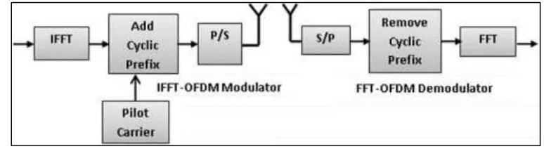
At the receiver the reverse steps of the encoding processes are employed, the cyclic prefix is removed and a serial to parallel conversion is established, FFT with N points is used to convert the signal from time to frequency domain. Then the effective channel is compensated after the OFDM demodulation, the signal de-mapper is used to recover the transmitted signal as shown in fig-5.
Fig. 5: Block Diagram of FFT-OFDM Modulator & Demodulator
But, in a 2×2 MIMO channel as shown in fig-6 below, used 2 transmit antennas, a transmission sequence, for example {x1, x2,
transmit antennas; could cluster the symbols into groups of two. In the first time interval, send x1 and x2 from the first and second
antenna. In second time slot, send x3 and x4 from the first and second antenna; send x5 and x6 within the third time slot. Notice that
as are grouping two symbols and sending them in one time slot, and need only (n/2) time slots to complete the transmission-data rate is doubled. This forms the straightforward clarification of a probable MIMO transmission scheme with 2 transmit antennas and a couple of receive antennas.
Fig. 6: Two Transmit & Two Receive (2×2) MIMO Channel
DWPT based MIMO-OFDM with Alamouti STBC
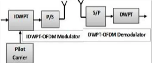
The idea of a wavelet was initial introduced for data compression as a result of functions are localized in each time and frequency domains. It ensures translation along the time and frequency planes by shifting and scaling severally, in contrast to the Fourier transform. Thus, once exploitation the DWPT, the determined signal is allowed variation in each time and frequency by multiresolution in line with the performed shifting and scaling. This property offers wavelet-based multicarrier systems signals larger hardiness against high Doppler shifts than the FFT. In contrast to the Fourier transform that applies a constant windo w to the signal, the DWPT uses a varied-sized windowing. This technique permits for discontinuities in the signal to be known as shown in fig-7.
Fig. 7: Block Diagram of DWPT-OFDM Modulator & Demodulator
VI. SIMULATION RESULTS
In this section, the simulation results are presented which show the performance comparison of FFT and DWPT based MIMO-OFDM systems in terms of BER in various wireless channels. The both FFT and DWPT based MIMO-MIMO-OFDM systems are developed, analyzed, and simulated in MATLAB.
The performance results of the system in AWGN channel, Flat Fading channel and Selective Fading channel are obtained using the MIMO-OFDM parameters as listed in Table-1. The bit rate used in this simulation is 5000 Mbps.
Table – 1 Simulation Parameters
Parameter FFT based MIMO-OFDM DWPT based MIMO-OFDM
Data Rate 5000Mbps 5000Mbps
Modulation QAM (16, 32 and 64) QAM (16, 32 and 64)
No. of sub-carriers 32 32
Doppler Frequency 500 Hz 500 Hz
Diversity Schemes 2X2 antennas 2X2 antennas
No. of bits per Symbol 32 32
No. of FFT points 64 -
Wavelet - Haar
Channel Model
During simulation, the right synchronization between the transmitted and also the received signals has been thought-about with available channel state information at the receiver. The channel coefficients are assumed to be static during 2 consecutive transmitted symbols within the heterogeneous channels. The performance of the projected system was tested in different channels. There are some restrictions and disadvantages in digital wireless communication systems between transmitter and receiver where received signals arrive at receiver with different power and time delay due to reflection, diffraction and scattering effects. For this reasons Bit Error Rate (BER) value is relatively high.
FFT based MIMO-OFDM System
In a FFT based MIMO-OFDM system with transmit antennas and receive antennas, if the channels for any pair of transmit-receive antennas are independent and experience flat fading, the maximum or full diversity gain. A common way of achieving the full diversity is through STBC.
BER Performance in FFT based MIMO-OFDM System at the AWGN Channel
The comparison is formed of the FFT primarily based MIMO-OFDM system between the QAM points of 16, 32 and 64 over the AWGN channel. The performance gain is wide between the systems that use 16 QAM points to the system with 64 points for higher SNR values. Higher performance gains are also observed when the SNR increases, as shown in fig-8.
Fig. 8: BER Performance of FFT based MIMO-OFDM System with STBC Alamouti (AWGN Channel)
BER Performance in FFT based MIMO-OFDM System at the Flat Fading Channel
In this section, the channel model used is the flat fading channel, where the bandwidth of the transmitted signal is smaller than the coherence bandwidth of the channel. Then, all frequency components of the transmitted signal undergo the same attenuation and phase shift in transmission through the channel. The value of the Doppler frequency is used in this simulation 500 Hz. The BER performance of FFT based MIMO-OFDM system with QAM of 16, 32 and 64 is shown in fig-9. The performance is reduced as the number of constellation mapping points increased from 16 to 64-point.
This section has clearly shown that the performance of the FFT primarily based MIMO-OFDM system is plauged by Doppler frequency additionally because the worth of QAM constellation points. The FFT primarily based MIMO-OFDM system simulated in flat fading channel performs better at the lower Doppler frequency as compared to its performance at the higher Doppler frequency.
BER Performance in FFT based MIMO-OFDM System at the Selective Fading Channel
The BER performance of the FFT based MIMO-OFDM system in the frequency selective fading channel is presented in this section. This channel indicates that the transmitted signal has a bandwidth greater than the coherence bandwidth of the channel. The frequency components of the transmitted signal with frequency separation exceeding the coherence bandwidth are subjected to different gains and phase shifts. The path gain 8 dB and the path delay is 1 sample.
The BER performance of FFT based MIMO-OFDM system with QAM of 16 and 64 is shown in fig-10. It shows that FFT based MIMO-OFDM system performs better with QAM constellation mapping 16-points as compared to its performance at the 32, 64-point. This shows that FFT based MIMO-OFDM system in the selective fading channel performs well at the number of constellation mapping 16-points compared to its performance at the 32, 64-point. The performance is reduced as the number of constellation mapping points increased from 16 to 64-point.
Fig. 10: BER Performance of FFT based MIMO-OFDM System at the Selective Fading Channel (500 Hz) and (16, 32 and 64 QAM)
DWPT based MIMO-OFDM System
BER Performance in DWPT based MIMO-OFDM System at the AWGN Channel
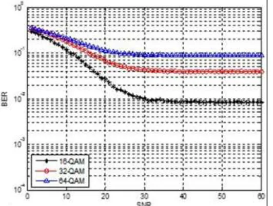
The performance gain is wide between the systems that use 16 QAM points to the system with 64 points for higher SNR values. Higher performance gains are also observed when the SNR increases. In the DWPT based MIMO-OFDM system, the BER performance at 16 point better than from 64 point.
Fig. 11: BER Performance of DWPT based MIMO-OFDM System with STBC Alamouti (AWGN Channel)
BER Performance in DWPT based MIMO-OFDM system at the Flat Fading Channel
Fig-12 shows the BER performance of the DWPT based MIMO-OFDM system using QAM 16 constellation mapping points over Flat Fading channel. From this figure it clearly shown that the performance of DWPT based MIMO-OFDM system is better than the FFT based MIMO-OFDM system at same QAM point.
Fig. 12: BER Performance of DWPT based MIMO-OFDM System with STBC Alamouti (Flat Fading Channel) at 500 Hz and (16, 32 and 64 QAM)
BER Performance in DWPT based MIMO-OFDM System at the Selective Fading Channel
In this section, if the bandwidth of the signal of interest exceeds the coherence bandwidth of the channel, the signal undergoes frequency selective fading (i.e. BS > BC). Viewed in the frequency domain, the channel causes different levels of attenuation for
different frequency components of the signal. Frequency selective fading is caused by multipath delays which approach or exceed the symbol period of the transmitted symbol (i.e. TS<στ) where στ is still the rms delay spread of the channel. In practice, TS ≤ 10στ
will result in a frequency selective channel; the channel introduces ISI.
As shown in fig-13, the BER performance of the DWPT based MIMO-OFDM system in the frequency selective fading channel. The frequency components of the transmitted signal with frequency separation exceeding the coherence bandwidth are subjected to different gains and phase shifts. The path gain -8 dB and the path delay is 1 sample.
Fig. 13: BER Performance of DWPT based MIMO-OFDM System with STBC Alamouti (Selective Fading Channel) at 500 Hz and (16, 32 and 64 QAM)
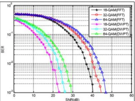
Fig. 14: BER Performance of DWPT and FFT based MIMO-OFDM System with STBC for AWGN at (16, 32 and 64 QAM)
Fig. 15: BER Performance of DWPT and FFT based MIMO-OFDM System with STBC for Flat Fading Channel at (16, 32 and 64 QAM)
VII.CONCLUSIONS
In this section a sum up of what novelties brings this section. This work presents the performance analysis of FFT based MIMO-OFDM system and DWPT based MIMO-MIMO-OFDM system in various fading channels. Their performance is also affected by the number of QAM points. Performance comparison in term of BER for both DWPT and FFT based MIMO-OFDM systems over AWGN channel, Flat Fading channel and Selective Fading channel is carried out according to the SNR. We can conclude then that DWPT based MIMO-OFDM system performs better than FFT based MIMO-OFDM system.
This contribution introduces a new transmission scheme for MIMO-OFDM systems. This scheme is based on channel coding using estimated channel parameters from a transmitted pilot data at the receiver end. Consequently, the prior information used by the coding scheme, will help the transmitted signal to adapt to the channel impairments and be more resilient to noise and interference. Simulation results confirm the high performance and the low complexity of the proposed scheme when compared to the conventional MIMO-OFDM system using Alamouti STBC Coding. The paper analyses the performance of FFT and DWPT based MIMO-OFDM systems under different constraints in Multi path fading channels. The simulation results are performed in terms of BER & SNR. It is found that the BER performance of the system decreases on increase in modulation order (number of constellation points). Performance of DWPT based MIMO-OFDM system with STBC get improves with unequal power conditions and with antenna selection technique. The DWPT based MIMO-OFDM system analysis is more immune to impulse and narrowband noises than conventional FFT based MIMO-OFDM system, also improves spectral efficiency and saves transmission power. DWPT based MIMO-OFDM system is more reliable than FFT based MIMO-OFDM system without putting any restriction on the number of antennas manipulated at the base station as well as at the receiver ends.
The results in terms of BER show that DWPT based MIMO-OFDM system are more efficient rather than the traditional FFT based MIMO-OFDM system. The performance gain is wider between the systems that use 16 QAM points to the system with 64 points for higher SNR values. Higher performance gains are also observed when the SNR increases. The performance results indicate that DWPT is a viable alternative to FFT but at the cost of higher complexity of equalization. Although, FFT offers a low complexity structure than DWPT, however, the use of CP reduces its spectral efficiency and wastes transmit power.
REFERENCES
[1] Jitendra Kumar Daksh, Ravi Mohan, Sumit Sharma, “Performance Analysis with Space-time coding in MIMO-OFDM Systems with Multiple Antennas”, International Journal of Advanced Computer Research Vol.3 No.2 Iss.10 June-2013.
[2] Monica Lamba and Charanjit Singh, “BER and Channel Capacity Improvement of MIMO-OFDM and Adaptive MIMOOFDM System by Modulation Technique (QAM)", International Journal of Computer Science & Engineering Technology (IJCSET), Vol. 5 No. 06, Jun 2014, pp. 734-742.
[3] M. Vani Divyatha, B. Siva Reddy, “Design and BER Performance of MIMO-OFDM for Wireless Broadband Communications”, International Journal of Modern Engineering Research (IJMER), Vol.3, Issue.3, May-June. 2013, pp-1382-1385.
[4] Vibha Rao and T. Malvika, ”Performance Analysis of MIMO-OFDM for Multiple Antennas” International Journal of Advanced Research in Electrical, Electronics and Instrumentation Engineering, Vol. 3, Issue 5, May 2014, pp. 9349-9355
[5] R. Suresh Babu, M. Suganthi and K. Ramasamy, “Ber Performance Comparison Of Multiple Antenna Using Space Time Block Coded Of dm System In Multipath Fading Environment”, ICTACT Journal On Communication Technology, Vol: 02, Issue: 01, March 2015.
[6] Hariprasad Nagarajan and AlameluNachiappan, "Performance Analysis of Discrete Wavelet Transform Based Multiple Output Orthogonal Frequency Division Multiplexing System for Different Wavelets in Different Channel Environment", American Journal of Applied Sciences Vol.10, No.12, 2017, pp.1521-1528.
![Fig. 1: Block Diagram of FFT-OFDM System [22]](https://thumb-us.123doks.com/thumbv2/123dok_us/8868587.1812471/2.612.180.437.460.595/fig-block-diagram-of-fft-ofdm-system.webp)