A LOOK AT SERVICE SAFETY
9
2
MODEL AND
APPLICATION
INFORMATION
I.
Compressor Model Number Codes . . . 10
II.
Condensing Unit Model Number Codes . . 11
III.
Serial Label Information . . . 12
IV.
Basic Application Information for
Hermetic Compressors . . . 14
For more free Tecumseh literature please visit
10
Chapter 2
I.
Compressor
Model
N
umber
Codes
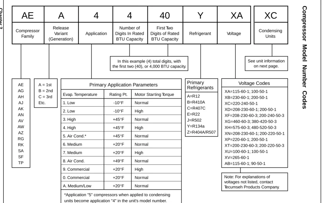
Figure 2-1. Compressor model number codes.
AE
A
4
4
40
Y
XA
Compressor FamilyXC
Condensing Units Release Variant (Generation) Number of Digits In Rated BTU Capacity First Two Digits of Rated BTU CapacityApplication Refrigerant Voltage
AE AG AH AJ AK AN AV AW AZ RG RK SA SF TP A = 1st B = 2nd C = 3rd Etc.
Primary Application Parameters
Evap. Temperature 1. Low 2. Low 3. High 4. High 5. Air Cond.* 6. Medium 7. Medium 8. Air Cond. 9. Commercial 0. Commercial A. Medium/Low*Application "5" compressors when applied to condensing units become application "4" in the unit's model number.
Motor Starting Torque Normal High Normal High Normal Normal High Normal High Normal Normal Rating Pt. -10°F -10°F +45°F +45°F +45°F +20°F +20°F +49°F +20°F +20°F +20°F
Primary
Refrigerants
A=R12 B=R410A C=R407C E=R22 J=R502 Y=R134a Z=R404A/R507 XA=115-60-1; 100-50-1 XB=230-60-1; 200-50-1 XC=220-240-50-1 XD=208-230-60-1; 200-50-1 XF=208-230-60-3; 200-240-50-3 XG=460-60-3; 380-420-50-3 XH=575-60-3; 480-520-50-3 XN=208-230-60-1; 200-220-50-1 XP=220-60-1; 200-50-1 XT=200-230-60-3; 200-220-50-3 XU=100-60-1; 100-50-1 XV=265-60-1 AB=115-60-1; 90-50-1Voltage Codes
See unit information on next page. In this example (4) total digits, with
the first two (40), or 4,000 BTU capacity.
Note: For explanations of voltages not listed, contact Tecumseh Products Company.
A LOOK AT SER
VICE SAF
ETY
Model and Application Inf
o rmation
11
II.
Condensing
Unit
Model
N
umber
Codes
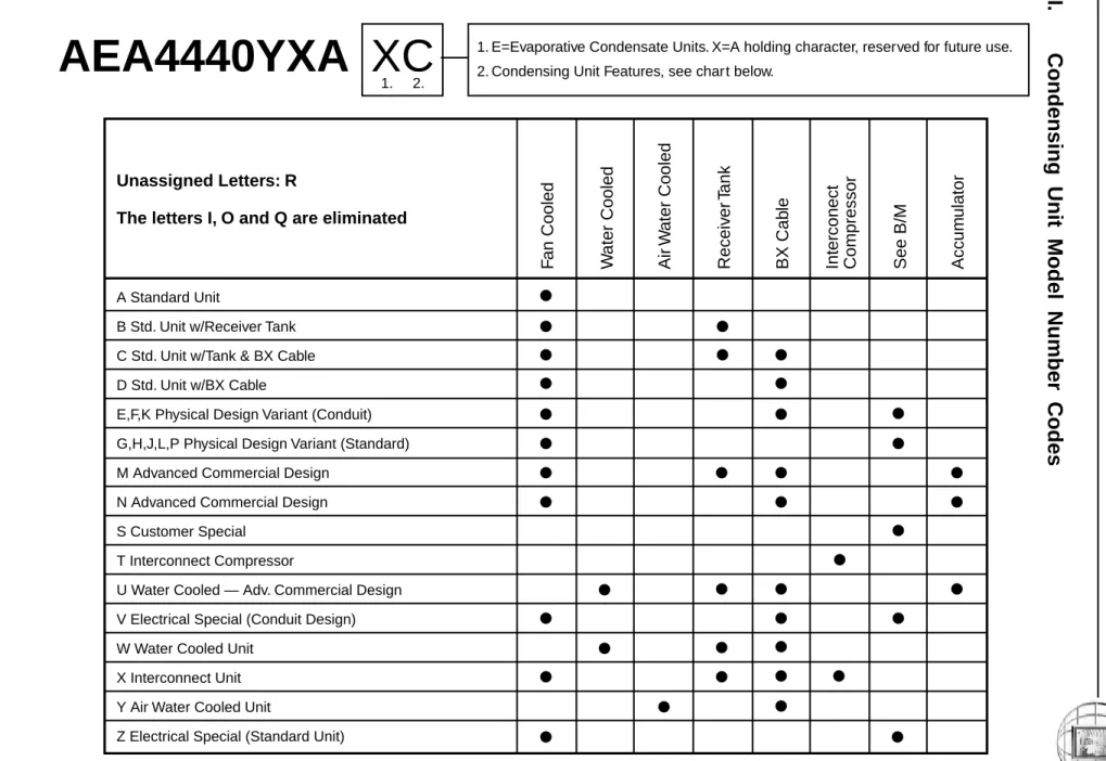
Figure 2-2. Condensing unit model number codes.
AEA4440YXA XC
A Standard Unit
B Std. Unit w/Receiver Tank C Std. Unit w/Tank & BX Cable D Std. Unit w/BX Cable
E,F,K Physical Design Variant (Conduit) G,H,J,L,P Physical Design Variant (Standard) M Advanced Commercial Design
N Advanced Commercial Design S Customer Special
T Interconnect Compressor
U Water Cooled — Adv. Commercial Design V Electrical Special (Conduit Design) W Water Cooled Unit
X Interconnect Unit Y Air Water Cooled Unit
Z Electrical Special (Standard Unit)
Unassigned Letters: R
The letters I, O and Q are eliminated
F
an Cooled
W
a
ter Cooled
Air
W
a
ter Cooled
Receiver
Tank
BX Cab
le
See B/M
Accum
u
lator
Inter
c
onect
Compressor
1.1. E=Evaporative Condensate Units. X=A holding character, reserved for future use. 2. Condensing Unit Features, see chart below.
12
Chapter 2
III.
Serial Label Information
The only source for complete compressor
informa-tion is on the compressor serial label. On earlier
compressors, the serial plate is usually spotwelded
on the upper housing of the compressor. For current
compressors, the serial label is affixed in the same
location. Both describe the characteristics of the
compressor.
The months are identified as identified in Table 2-1.
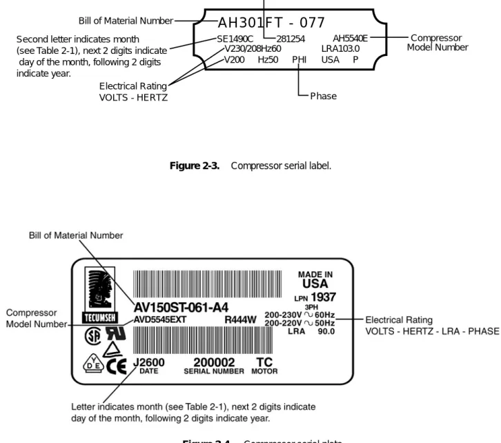
Figure 2-3. Compressor serial label.
AH301FT - 077
SE1490C V230/208Hz60 V200 Hz50 PHI USA LRA103.0 AH5540E P 281254 Serial Number Compressor Model Number Bill of Material NumberPhase Electrical Rating
VOLTS - HERTZ Second letter indicates month (see Table 2-1), next 2 digits indicate
day of the month, following 2 digits indicate year.
A LOOK AT SERVICE SAFETY
Model and Application Information
13
HP.
1
Manufacturing Code Date Month = September
Year = 2000 0J0
COMPRESSORS VOLTAGE EVAP. RANGE (ºF) THERMALLY PROTECTED L.R.A. E.A. NO FANS: NO. MAX. FUSE OZ. CHARGE MAX. CKT. BKR.
(HACR. TYPE PER NEC.) REFRIG. PROTECTED PH.
52594-1
HI SIDE LO SIDE DESIGN PRESSURE P.S.I. MIN. CIRCUIT AMPACITY F.L.A. E.A. PH. 60 HZ 50 HZ
58.8
8.8
1
0J00066332
2C234-9
AKA9446EXAXC
1.4
20
R-22
444
12.4
350
150
1
115 -10F TO +45F 35W SER EM ® MOD (1P) MADE IN USA 1 THERMALLY R.L.A. E.A. PThe letter represents the month (see Table 2-1). The numbers represent the year.
Figure 2-5. Condensing unit serial label.
Table 2-1: Serial Label Month Identifiers
January - A
March - C
May - E
July - G
September - J
November - L
14