FAST ANALYSIS AND DESIGN OF FREQUENCY SELECTIVE SURFACE USING THE GMRESR-FFT METHOD
W. Zhuang, Z. H. Fan, D. Z. Ding, andY. Y. An
Department of Communication Engineering Nanjing University of Science and Technology Nanjing 210094, China
Abstract—In this paper, frequency selective surfaces (FSSs) are analyzed and designed. The analytical procedure is based on method of moments (MoM). The generalized minimal residual recursive method combined with fast Fourier transform (GMRESR-FFT) is utilized to accelerate the solution of the matrix equation. Our numerical results show that the GMRESR-FFT method can converge at least 3 times faster than the generalized minimal residual fast Fourier transform method (GMRES-FFT). In this paper, the cross dipoles are first used to design the FSS filter with a passband at 300 GHz and a stopband at 450 GHz, and then the Jerusalem cross slots are utilized to avoid grating lobes and improve the bandwidth of FSS. Numerical results demonstrate the validity and efficiency of the presented method.
1. INTRODUCTION
The frequency selective surfaces (FSSs) often consist of an array of periodic metallic patches or a conducting sheet periodically with apertures [1]. FSSs have been intensively studied since the mid 1960s. Over the years, FSSs have been widely used, including filters, laser cavity output couplers, polarization diplexers, spectral diplexers, and so on [2–9]. Nowadays, the fabrication of FSSs is not a problem, but the analysis and design become more and more important.
In this paper, the FSS analysis method involves solving an electric field integral equation (EFIE) for the current distribution on the FSS and employs rooftop subdomain basis and testing functions with the framework of the Galerkin testing procedure [10]. The GMRESR-FFT
method is used to accelerate the solution of the impedance matrix equation [11–13]. This method involves an outer generalized conjugate residual method (GCR) [14] and an inner generalized minimal residual method (GMRES) [15, 16], where the inner GMRES acts as a variable preconditioner [13, 17–20] for the outer GCR. A typical FSS structure is analyzed and the good results demonstrate the validity and efficiency of the proposed algorithm. Our numerical results show that the GMRESR-FFT method can converge at least 3 times faster than the generalized minimal residual-fast Fourier transform (GMRES-FFT) method.
The cross dipoles slots are first used to design the FSS filter, but the stopband frequency does not coincide with the first zero of the transmission coefficient. Therefore, in this paper, Jerusalem cross slots are proposed to overcome this difficulty. With the decrease of the periodicity size, the grating lobes vanish. From the results, the filter exhibits much better performance than the one based on cross dipole slots, with a (−3 dB) passband width of 30 GHz and a (−20 dB) stopband width of 54 GHz.
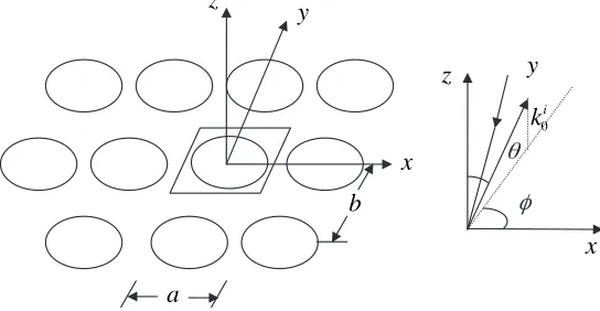
2. ANALYSIS OF THE FSS
Figure 1 shows the geometry of a free-standing FSS model. aandbare periodicity of the unit cell in thex- andy-directions, respectively. ki0
is the incident wave number;θ, φare the angles of the incident plane wave. The scattered fieldEsfrom a conducting patch on thex-yplane
b
a
z
y
x
x
y
z
0 i
k
θ
φ
can be calculated as follows,
Es=−jωµ0A+
1 jωε0∇
(∇ ·A) (1)
where
A(r) =
Gr,rJrdr (2)
Here,Gis the Green’s function in the free space andJis the unknown current. On the conducting patch, the tangential electric filed, denoted by a subscriptt, vanishes.
Einct +Est = 0 (3)
Here, the superscripts s and inc correspond to the scattered and incident fields, respectively. Subsequently, Equation (1) becomes
Einct =jωµ0At(r)− 1 jωε0
[∇(∇ ·A(r))]t (4) For periodic structure, the Floquet’s periodicity condition is enforced, and we can obtain the following equation,
−
Eincx (x, y)
Eincy (x, y) = m n ˜
Gxx G˜xy ˜
Gyx G˜yy
˜
Jx(αm, βn) ˜
Jy(αm, βn)
ej(αmx+βny) (5)
where Eincx (x, y) and Eincy (x, y) represent the x, y components of the incident fields; ˜Gare the spectral counterparts ofG; and αand β are the spectral variables corresponding to the spatial ones (x, y). The explicit expressions forαm and βn are as follows,
αm = 2πm
a +k0sinθcosφ βn=
2πn
b +k0sinθsinφ
(6)
If an FSS is embedded in or printed on the multilayered media, Green’s functions in the free space shown in (5) should be displaced with that in multilayered media shown in [10]. The unknown currents ˜Jx and
˜
Jy are solved by using the Galerkin’s procedure with the rooftop basis functions for the current discretization.
The final equations can be written as follows,
Zxx Zxy
Zyx Zyy
Ix
Iy
=
Vx0 Vy0
The impedance matrixZis obviously a dense and symmetric complex matrix. When direct-solution methods such as LU decomposition are used, the computational complexity is O(N3). As the problem size increases, the computational expense of these operations becomes prohibitive. This has led to the development of various iterative algorithms with the FFT technique for solving the surface current with computational complexity ofO(NlogN), whereN denotes the number of unknowns. Here the details are omitted (see [11, 19–27]). After the unknown currents are obtained, the transmission coefficient can be calculated from the unknown currents.
During the iterative process, it is desirable to precondition the coefficient matrix such that the modified system is well conditioned and can converge in significantly fewer iterations than the original system. Next, we will introduce the GMRESR-FFT algorithm.
3. GMRESR ALGORITHM
Consider the iterative solution of large linear systems of the form:
Ax=b (8)
method [27]. The method organizes the numerical factorization into a number of steps and each involves the formation of a dense smaller frontal matrix followed by its partial factorization.
The basic principle of preconditioning is to use iterative methods for solving a modified system such as
AM−1(Mx) =b (9)
where M denotes the preconditioning matrix. Clearly, the matrix
AM−1 need not to be formed explicitly. We need only to solve
M−1v whenever such an operation is required for any vector v. A
fundamental requirement is that it should be easy to compute. In some cases, solving a linear system with the matrixMconsists of forming an approximate solution by performing one or a few steps of a relaxation type method. It is natural to consider preconditioners that do not use only a single step of an iterative method but as many as needed to solve a linear system within a given tolerance. For the GCR algorithm, this can be achieved with the help of rather simple modification of the standard algorithm, which is referred as GMRESR [12]. The GMRESR algorithm consists of GCR as the outer algorithm and GMRES as inner algorithm to get an approximation to M−1v.
The GMRESR algorithm is given bellow and the details are described in [12, 13].
1. Selectx0,m,tol
2. r0 =b−x0, k=−1
3. Whilerk+12 > toldo
4. k=k+ 1
5. SolveAu0k=rk approximately by m steps of GMRES
6. c0
k=Au0k
7. Fori= max(0, k−j), . . . , k−1 do 8. αi=cTi c
(i)
k ; c
(i+1)
k =c
(i)
k −αici; u
(i+1)
k =u
(i)
k −αiui
9. End do
10. ck=ck(k)/c(kk)2; uk=u(kk)/u(kk)2 11. xk+1=xk+ukcTkrk; rk+1=rk+ckcTkrk
u0k = rk, then no preconditioning is performed and the exact GCR method is obtained. Hence, it is obvious that any vectors can be used for u0k and the algorithm still works. In general, the better the choice of u0k the faster the convergence can be obtained. The optimal choice, of course, isu0k=A−1rk. Therefore, the key point is to choose a suitable approximation to A−1r
k. In the above implementation, as can be seen from line 5 of the algorithm, m steps of GMRES iteration are added (applied) to get a better approximation toA−1rk. Meanwhile, a truncation strategy in line 7 is introduced to restrict memory requirements, where we only update from the last j outer iterations. As can be seen from the algorithm, there is no additional cost in memory for GMRESR when compared to the standard GCR method, while the advantage of variable preconditioning is obtained and it can be quite helpful, especially in the context of developing robust iterative methods or for developing robust preconditioners. Increasing the number of inner iterations m, better approximation of u0k to A−1rk will be arrived. Hence, it is possible to gradually and monotonously improve the quality of the method by increasing m. However, the computational complexity for inner GMRES is also increased. Therefore, by tuningm, it is possible to achieve a balance between the computational cost and the efficiency of the algorithm.
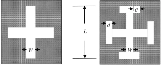
4. DESIGN METHODS
In this paper, an FSS filter will be designed with a passband at 300 GHz and a stopband at 450 GHz when the incident E-field has TE-z polarization and incident angelθ= 20◦, andϕ= 9 0◦. The filters consist of two-dimensional aperture arrays printed on silicon substrates
L
d
e
W W
FSS unit cell
Thickness
Figure 3. Side view of the FSS.
wafer [4] with a relative dielectric constant of 11.8 as shown in Figure 2 (side view in Figure 3). The primary parameters of the FSS have to be set:
• The thicknessh of the substrate
According to Fabry-Perot resonance condition [4], the substrate thicknessh is defined in (10)
h=k· c
2fpass√εr · cos
arcsin
1
√ε
r sinθ
(10)
where fpaa = 300 GHz, k = 2 and c is the speed of light in vacuum. Therefore, the required thickness ish≈289.7µm for easy fabrication, the thickness of wafers can be set at h≈302µm.
• The lengthL of the cross dipole slots
For easy fabrication, the thickness of wafers can be set asW L; the lengthL of the slots should be half wavelength in the substrate.
L= λ 2 =
c 2fpass√εa εa=
1 +εr 2
(11)
where εa is the effective dielectric permittivity, approximately. For a resonance at fpass = 300 GHz, the slots length is L = 0.197µm. Moreover, the initial value of slot width is set to W = 0.03 mm. It should be mentioned that the slight difference of W can results in slight difference of resonance frequency.
•The size of the unit cell (Tx=Ty)
The size of the unit cell Tx can be used to define the stopband frequency of the filter. According to [4], the required size of the unit cell is given by
Tx =Ty =
c fstop
√
εr+ sinθsinφ
From (12), the periodicity is Tx =Ty = 0.176 mm for the FSS with a stopband at 450 GHz. However, the slot length L is bigger than the size of the unit cell. Therefore, Tx and Ty are initially set to be 25% larger than the length of the slots (Tx=Ty = 0.25 mm).
In the optimization process,Lis modified to satisfy the passband frequency; meanwhile, Tx and Ty should be modified to obtain the desired stopband frequency and other parameters are kept constant.
5. NUMERICAL RESULTS
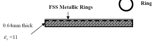
The first analysis considers the metallic ring elements printed on 0.064-cm-thick Duroid substrate (RT-6010.5) with a relative dielectric constant of 11.0 (as shown in Figure 4). All identical ring elements are arranged in square lattice with element spacing equal to 0.724 cm. Each ring has an inner diameter of 0.56 cm and an outer diameter of 0.61 cm. Both the measured and calculated transmission coefficient of the single-screen FSS versus frequency are presented in Figure 5. Good agreement is obtained between the calculations and the measurements [34], which shows the validity of the proposed method in this paper.
Figure 4. Side view of the ring element FSS.
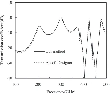
Next, an FSS is designed with a passband at 300 GHz and stopband at 450 GHz. The geometrical dimensions of the FSS are listed in Table 1 (filter S2). The frequency response characteristics calculated by our method and the commerical CAD tool — Ansoft Designer [35] are shown in Figure 6. Good agreement shows the validity of the proposed method in this paper.
Figure 7 gives the CPU times of the GMRESR-FFT and GMRES-FFT algorithms versus frequency. It is found from Figure 7 that the GMRESR-FFT algorithm can be at least three times faster than GMRES-FFT when the residual errors reach 10−4 over all frequencies.
-40 -30 -20 -10 0
0 5 10 15
Frequency(GHz)
T
ran
sm
is
si
on
c
oef
fi
ci
en
t
(d
B
)
Simulated
Measured [34]
Figure 5. Transmission coefficient versus frequency for ring element FSS.
-40 -30 -20 -10 0 10
100 200 300 400 500
Frequency(GHz)
T
rans
mis
si
on coef
fi
cient(
dB
)
Our method
Ansoft Designer
Figure 6. Transmission coefficients versus frequency of the FSSs with the cross dipole slots calculated by our method and the Ansoft Designer.
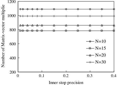
taken to be 40. It can be seen from Figure 8 that the number of matrix-vector multiplies is invariable with the decrease of the inner stop-precision. The number decreases first and then increases with the increase of the maximum number of inner iterations. When the maximum number of inner iterations is 15, the number of matrix-vector multiplies is minimal.
0 100 200 300 400 500
100 200 300 400 500 Frequency (GHz)
C
P
U
time
s(
s)
GMRES-FFT GMRESR-FFT
Figure 7. CPU times versus frequency calculated by GMRES-FFT and GMRESR-FFT algorithm.
200 400 600 800 1000 1200
0 0.1 0.2 0.3 0.4
Inner stop precision
N
u
mb
er
of
M
atr
ix
-v
e
ctor
mu
ltip
li
e
N=10 N=15 N=20 N=30
Figure 8. Number of matrix-vector multiplies for different inner stop precision with outer stop-precision of 10−4.
0.0001 0.001 0.01 0.1 1
0 500 1000 1500
Number of Matrix-Vector Multiplies
Residual Norm
m=20 m=30 m=40 m=50
Figure 9. Residual norm histories with different truncated value m and stop precision of 10−1 in the inner iteration and 10−4 in the outer
iteration.
Table 1. Geometry of the 300 GHz filters based on cross dipole slots (S1–S3) and Jerusalem cross slots (J1–J3).
Filters L [µm]
W [µm]
d [µm]
e [µm]
Tx=Ty [µm]
fpass [GHz]
S1 196 32 - - 220 288
S2 184 32 - - 220 300
S3 176 32 - - 220 307
J1 160 32 16 20 176 299
J2 152 32 16 20 176 300
J3 144 32 16 20 176 310
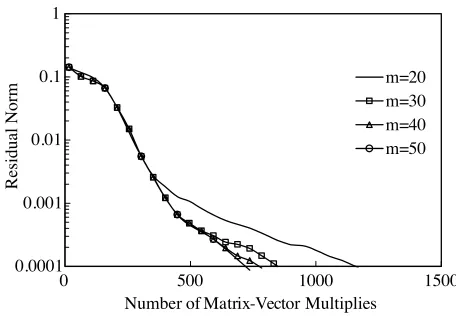
the truncated valuem is selected to be 50.
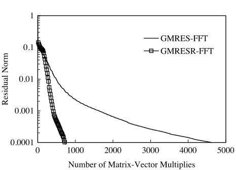
To check the computational efficiency of our proposed method, we compare the convergence history of the GMRESR (50) and GMRES (50) methods combined with the FFT technique. The stop precision for restarted GMRES is 10−4. The maximum number of inner iterations is
15 and the stop precision in the inner iteration is taken to be 10−1 and
10−4 for the outer iteration. Figure 10 shows the residual norm history
0.0001 0.001 0.01 0.1 1
0 1000 2000 3000 4000 5000
Number of Matrix-Vector Multiplies
Residual Norm
GMRES-FFT GMRESR-FFT
Figure 10. Residual norm histories at 300 GHz calculated by GMRES-FFT and GMRESR-FFT algorithm.
The design above fulfills the design specifications, with a −3 dB passband of 20 GHz and a −20 dB stopband of 20 GHz. Moreover, in order to show the efficiency of manufacturing tolerances, two other filters operating at slightly lower and higher frequency were also designed (filter S1 and S3 in Table 1). The frequency response of all these FSSs, calculated by our proposed method, is also shown in Figure 11. In all cases, the stopband frequency does not coincide with the first zero of the transmission coefficient, due to the value ofTx=Ty larger than those resulting from (12).
This drawback can be avoided by adopting Jerusalem cross aperture element, which permits obtaining the same resonance frequency with a reduced element length. The geometrical dimensions of the FSS required are listed in Table 1 (filter J2), and the dimensions of two other filters are also shown in Table 1 (filter J1 and J3), which has slightly lower and higher resonance frequency. The frequency response characteristics are shown in Figure 12. The filter J2 in Figure 10 exhibits much better performance than the one S2 based on the cross dipoles, with a−3 dB passband of 30 GHz and a −20 dB stopband of 54 GHz.
-40 -30 -20 -10 0
100 200 300 400 500
Frequency (GHz)
Tr
an
sm
is
si
on
co
ef
fi
cien
t
(d
B)
S1 S2 S3
Figure 11. Frequency responses of the FSSs with the cross dipoles slots.
-40 -30 -20 -10 0
100 200 300 400 500
Frequency (GHz)
T
ran
sm
is
si
on
coef
fi
ci
en
cy
(
d
B
)
J1 J2 J3
-40 -30 -20 -10 0
100 200 300 400 500
Frequency (GHz)
T
ran
sm
is
si
on
coef
fi
ci
en
cy
(d
B)
This paper- lossy
This paper- lossless
-3 -2 -1 0
290 295 300 305 310
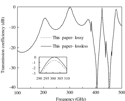
Figure 13. Frequency responses of filter S2, calculated by our method (both lossy and lossless case).
6. CONCLUSION
In this paper, an MoM-based computer code has been developed to design the FSS filter with a passband at 300 GHz and a stopband at 450 GHz. The GMRESR-FFT method is used to accelerate the solution of the impedance matrix equation. A typical FSS structure is analyzed and GMRESR-FFT method can converge 3 times faster than the GMRES-FFT method. The cross dipoles are first used to design the FSS filter, but the stopband frequency does not coincide with the first zero of the transmission coefficient. In order to overcome the difficulty, the Jerusalem cross slots are proposed to reduce the size of the unit cell and improve the width of the stopband. From the results, the filter exhibits much better performance than the one based on cross dipole slots, with a −3 dB passband of 30 GHz and a passband of−20 dB stopband of 54 GHz. In the end, the efficiency of the dielectric loss to the FSS is studied. The results demonstrate that the insertion loss near the resonance frequency is increased with 0.6 dB and unchanged elsewhere.
ACKNOWLEDGMENT
Youth Natural Science Foundation of China under Contract Number 60325103.
REFERENCES
1. Munk, B. A., Frequency Selective Surfaces Theory and Design, John Wiley & Sons, Inc., 2000.
2. Schimert, T. R., A. J. Brouns, C. H. Chan, and R. Mittra, “Investigation of millimeter-wave scattering from frequency selective surfaces,”IEEE Trans. on Microwave Theory and Tech., Vol. 39, 315–322, 1991.
3. Shen, Z., N. Ito, E. Sakata, C. W. Domier, Y. Liang, N. C. Luhmann, Jr., and A. Mase, “Frequency selective surface notch filter for use in a millimeter wave imaging system,” IEEE
International Symposium on Antennas and Propagation, 4191–
4194, 2006.
4. Biber, S., M. Bozzi, and O. G¨unther, “Design and test-ing of frequency-selective surfaces on silicon substrates for submillimeter-wave applications,” IEEE Trans. Antennas
Prop-agat., Vol. 54, 2638–2645, 2006.
5. Wu, G., V. Hansen, E. Kreysa, and H.-P. Gemuend, “Design and optimization of FSS structures for applications in (sub) millimeter astronomy using a PSO algorithm,” IRMMW-THz 2006, 401, 2006.
6. Pirhadi, A., F. Keshmiri, M. Hakkak, and M. Tayarani, “Analysis and design of dual band high directive EBG resonator antenna using square loop FSS as superstrate layer,” Progress In
Electromagnetics Research, PIER 70, 1–20, 2007.
7. Oraizi, H. and M. Afsahi, “Analysis of planar dielectric multilayers as FSS by transmission line transfer matrix method (TLTMM),” PIER 74, 217–240, 2007.
8. Hosseini, M., A. Pirhadi, and M. Hakkak, “A novel AMC with little sensitivity to the angle of incidence using 2-layer jerusalem cross FSS,”Progress In Electromagnetics Research, PIER 64, 43– 51, 2006.
9. Delihacioglu, K., S. Uckun, and T. Ege, “FSS comprised of one-and two-turn square spiral shaped conductors on dielectric slab,”
Progress In Electromagnetics Research B, Vol. 6, 81–92, 2008.
11. De Sturler, E., “Nest Krylov methods based on GCR,”Journal of
Computational and Applied Mathematics, Vol. 67, 15–41, 1996.
12. Van der Vorst, H. A. and C. Vuik, “GMRESR: A family of nested GMRES methods,”Num. Lin. Alg. Appl., Vol. 1, 369–386, 1994. 13. Rui, P. L. and R. S. Chen, “Robust GMRES recursive method
for fast finite element analysis of 3-D electromagnetic problems,”
Microwave and Optical Technology Letters, Vol. 49, No. 5, 1010–
1015, 2007.
14. Eisenstat, S. C., H. C. Elman, and M. H. Schultz, “Variational iterative methods for non-symmetric systems of linear equations,”
SIAM J. Numer. Anal., Vol. 20, 345–357, 1983.
15. Saad, Y. and M. H. Schultz, “GMRES: A generalized minimal residual algorithm for solving nonsymmetric linear systems,”
SIAM J. Sci. Statist. Comput., Vol. 7, 856–869, 1986.
16. Chen, R. S., D. X. Wang, and E. K. N. Yung, “Efficient analysis of millimeter wave ferrite circulators by GMRES iterative algorithm,” International Journal of Infrared and Millimeter
Waves, Vol. 24, No. 7, 1199–1214, 2003.
17. Ping, X. W., R. S. Chen, K. F. Tsang, and E. K. N. Yung, “The SSOR-preconditioned inner outer flexible GMRES method for the FEM analysis of EM problems,” Microwave and Optical
Technology Letters, Vol. 48, No. 9, 1708–1712, 2006.
18. Ding, D. Z., R. S. Chen, D. X. Wang, W. Zhuang, and E. K. N. Yung, “Application of the inner-outer flexible GMRES-FET method to the analysis of scattering and radiation by cavity-backed patch antennas and arrays,” International Journal of
Electronics, Vol. 92, No. 11, 645–659, 2005.
19. Chen, R. S., D. Z. Ding, Z. H. Fan, E. K. N. Yung, and C. H. Chan, “Flexible GMRES-FFT method for fast matrix solution: Application to 3D dielectric bodies electromagnetic scattering,” International Journal of Numerical Modelling:
Electronic Networks, Devices and Fields, Vol. 17, No. 6, 523–537,
2004.
20. Mo, L., R. S. Chen, P. L. Rui, and X. P. Feng, “Fast analysis of microwave integrated circuits by use of the inner-outer flexible GMRES-FFT method,” Microwave and Optical
Technology Letters, Vol. 43, No. 5, 409–413, 2004.
22. Chen, R. S., E. K. N. Yung, C. H. Chan, and D. G. Fang, “Application of preconditioned CG-FFT technique to method of lines for analysis of the infinite plane metallic grating,”Microwave
and Optical Technology Letters, Vol. 24, No. 3, 170–175, 2000.
23. Chen, R. S., Z. H. Fan, and E. K. N. Yung, “Analysis of electromagnetic scattering of three-dimensional dielectric bodies using Krylov subspace FFT iterative methods,” Microwave and
Optical Technology Letters, Vol. 39, No. 4, 261–267, 2003.
24. Rui, P. L., R. S. Chen, Z. H. Fan, E. K. N. Yung, C. H. Chan, Z. Nie, and J. Hu, “Fast analysis of electromagnetic scattering of 3D dielectric bodies with augmented GMRES-FFT method,”
IEEE Trans. Antennas Propagat., Vol. 53, No. 11, 3848–3852,
2005.
25. Rui, P. L., R. S. Chen, X. P. Feng, L. Mo, and E. K. N. Yung, “Fast analysis of microwave integrated circuits by use of the loose GMRES-FFT method,” International Journal of RF and
Microwave CAD Engineering, Vol. 15, No. 6, 578–586, 2005.
26. Ding, D. Z., R. S. Chen, Z. H. Fan, E. K. N. Yung, and C. H. Chan, “Fast analysis of electromagnetic scattering of 3D dielectric bodies by use of the loose GMRES-FFT method,”International Journal
of Electronics, Vol. 92, No. 7, 401–415, 2005.
27. Chen, R. S., L. Mo, and E. K. N. Yung, “Multifrontal method preconditioned GMRES-FFT algorithm for fast analysis of microstrip circuits,” International Journal for Computational
and Mathematics in Electrical and Electronic Engineering, Vol. 24,
No. 1, 94–106, 2005.
28. Chen, R. S., X. W. Ping, E. K. N. Yung, C. H. Chan, et al., “Application of diagonally perturbed incomplete factorization preconditioned conjugate gradient algorithms for edge finite element analysis of Helmholtz equations,”IEEE Trans. Antennas
Propagat., Vol. 54, No. 5, 1604–1608, 2006.
29. Chen, R. S., X. W. Ping, and E. K. N. Yung, “SSOR preconditioned GMRES for the FEM analysis of waveguide discontinuities with anisotropic dielectric,”International Journal
of Numerical Modelling, Vol. 17, No. 2, 105–118, 2004.
30. Chen, R. S., E. K. N. Yung, C. H. Chan, and D. G. Fang, “Ap-plication of SSOR preconditioned conjugate gradient algorithm to edge-FEM for 3-dimensional full wave electromagnetic boundary value problems,” IEEE Trans. on Microwave Theory and Tech., Vol. 50, No. 4, 1165–1172, 2002.
wave scattering,”International Journal of Infrared and Millimeter
Waves, Vol. 21, No. 8, 1281–1301, 2000.
32. Chen, R. S., K. F. Tsang, and E. K. N. Yung, “An effective multigrid preconditioned CG algorithm for millimeter wave scattering by an infinite plane metallic grating,” International
Journal of Infrared and Millimeter Waves, Vol. 21, No. 6, 945–
963, 2000.
33. Chen, R. S., D. G. Fang, K. F. Tsang, and E. K. N. Yung, “Analysis of electromagnetic wave scattering by an electrically large metallic grating using wavelet-based algebratic multigrid preconditioned CG method,” Progress In Electromagnetics
Research, PIER 31, 89–112, 2001.
34. Huang, J., T. K. Wu, and S. W. Lee, “Tri-band frequency selective surface with circular ring elements,” IEEE Trans. Antennas
Propagat., Vol. 42, No. 2, 166–175, 1994.