ISSN(Online): 2320-9801 ISSN (Print) : 2320-9798
I
nternational
J
ournal of
I
nnovative
R
esearch in
C
omputer
and
C
ommunication
E
ngineering
(An ISO 3297: 2007 Certified Organization)
Vol. 4, Issue 2, February 2016
Two Parallel Slot Microstrip Antenna over
Frequency Selective Surface with Jerusalem
Cross Components
Geeta, Ramit Kirti Saran, Amit Kirti Saran
Assistant Professor, Dept. of Electronics and Communication Engineering, AIT, Rampur, Uttar-Pradesh, India
B. Tech Student, Dept. of Electronics and Communication Engineering,Apex Institute of Technology, APJ Abdul
KalamTechnical University, Lucknow, U.P, India
B. Tech Student, Dept. of Electronics and Communication Engineering,Apex Institute of Technology, APJ Abdul
KalamTechnical University, Lucknow, U.P, India
ABSTRACT: FSS consisting of standard Jerusalem cross components was initial accustomed study its impact on the bandwidth and resonant frequencies of a U-slot patch antenna. Supported the simulation expertise of the primary partial study, another FSS with Jerusalem cross components was projected to enhance the bandwidths, antenna gains, and return losses of a smaller Two Parallel slot patch antenna at 5.8 GHz frequency for Bluetooth and local area network applications ,severally .Measured information of the return loss , radiation diagram, and antenna gain of this smaller E slot patch antenna were conjointly bestowed. It’s tried that the smaller U-slot patch antenna established with a FSS consisting of Jerusalem cross components feature a smart performance with comfortable information measure and better gain. Here microstrip patch antenna is placed over the layer of FSS. The objective in such design to analyze the return loss, gain, efficiency and VSWR for microstrip patch antenna which operate at 5.8 GHz.
KEYWORDS: FSS, Jerusalem cross, Microstrip patch antenna , Coax-feed method,Return loss,Gain.
I. INTRODUCTION
ISSN(Online): 2320-9801 ISSN (Print) : 2320-9798
I
nternational
J
ournal of
I
nnovative
R
esearch in
C
omputer
and
C
ommunication
E
ngineering
(An ISO 3297: 2007 Certified Organization)
Vol. 4, Issue 2, February 2016
wave. These characteristics of FSS structures may be accustomed improve the radiation potency, gain, and information measure of a patch antenna. The impact of a FSS on patch antenna performance depends on the lattice pure mathematics, component regularity, and also the electrical properties of the substrate materials .In this; the Two Parallel slot patch antenna is projected to be at the inherent downside of the slender information measure of the microstrip patch antenna. However, the resonant frequency is also shifted from operative frequency and also the information measure is also narrowed down once a wide-band Two Parallel slot patch antenna changes its pure mathematics and size to suit completely different environments. Within the initial a part of this communication, we tend to report on a dual-band FSS consisting of standard Jerusalem cross component that was accustomed study the impact on the bandwidths and resonant frequencies of a Two Parallel slot patch antenna at 5.8 GHz. For Bluetooth and local area network applications , severally .Supported the simulation expertise of the primary partial study, another FSS with changed Jerusalem cross components established during a new Two Parallel slot patch antenna with a smaller size was used for more studies to enhance the antenna bandwidths, antenna gains, and resonant frequencies at a pair of.45 and 5.8 GHz, severally. In simulations, the characteristics of Two Parallel patch antennas were obtained by exploitation the Ansoft high-frequency structure simulator (HFSS).Simulation results of the return loss , radiation pattern diagram, and gain of this new Two Parallel patch antenna were valid by measuring information.
II. THE TWO PARALLEL PATCH ANTENNA WITH A FSS
The Two Parallel patch antenna and its dimensions are given below. In my work, a concentric line with a characteristic electrical phenomenon of fifty ohms is employed because the feed of the Two Parallel patch antenna. The inner conductor of the concentric line is connected to the patch material substrate, and also the outer conductor is shorted to the metal like plate on the opposite aspect of the patch antenna. The FR4 material is employed for the material substrate with a thickness of four.4 mm. The relative material constant and electrical loss tangent of the substrate square measure adopted to be four (.4) and 0.02 at frequencies a pair of to six rate, severally. This Two Parallel patch antenna established with a FSS consisting of standard Jerusalem cross components is shown in Fig. 2. The FR4 material is additionally used for the higher and lower material substrates of the U-slot patch antenna with a FSS. The thickness of the higher and lower material substrate is unbroken at 4.40mm, whereas the thickness of the lower material substrate H , might vary from a pair of .2 to 3.2 mm.The Frequency Selective Surfaces (FSS) created with regular Jerusalem cross components is employed to enhance the antenna performance. The thickness of the highest metal like patch, the FSS, and also the bottom metal like plate is .035 mm. Fig. 3 shows an regular Jerusalem cross component. Therefore, the structure of the FSS may be viewed as behaving sort of a tuned network of equivalent LC circuits. By fixing the Jerusalem cross component pure mathematics the values for L and C may be changed, and also the resonant frequency is modified consequently. Comparisons of simulation results of return losses for the U-slot patch antenna established with and while not a FSS square measure studied. Simulation results were investigated by checking the impedance matching with higher than 10 dB return losses. From observations, the resonant frequencies of the U-slot patch antenna established with and while not a FSS square measure found to be close to the two resonant frequencies of 2.5GHz and 5.6 GHz rate for the impedance matching with higher than 10dB return loss.
III. ANTENNA THEORY
ISSN(Online): 2320-9801 ISSN (Print) : 2320-9798
I
nternational
J
ournal of
I
nnovative
R
esearch in
C
omputer
and
C
ommunication
E
ngineering
(An ISO 3297: 2007 Certified Organization)
Vol. 4, Issue 2, February 2016
circuits. However, it is well-know that a patch antenna on a dielectric substrate may have a very narrow bandwidth due to surface wave losses. The surface wave existed on the patch antenna will continue to propagate until it meets a discontinuity. When the surface wave meets the discontinuity, it may radiate and couple energy to the discontinuity. The surface wave will reduce antenna efficiency, gain, and bandwidth .To achieve multi-band and wide-band operation in a patch antenna design, the frequency selective surface (FSS) is implemented or imbedded in a patch antenna in recent years.FSS can be used as a filter, substrate and superstrate. In this designed FSS is used as a substrate.
IV. MICROSTRIO PATCH ANTENNA WITH FSS
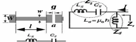
The dielectric material used for both the substrate is RT Duroid 5880 (the relative dielectric constant is 2.2) and the thickness chosen to be 3.16 mm for the lower substrate and for upper substrate is 1.58mm .There is layer of jerusalem cross element in between the two substrate ,this whole structure is known as frequency selective surface. All the parameters (a, l, w, W) depicted in Figure 1. Except g, are used as optimization variables. Where W and (a-g)/2 are length and width of the edge parts while l and w indicate the length and width of the straight portion of cross respectively.
Figure 1. The unit cell geometry for the JC –FSSFigure 2. Patch antenna on FSS
The length Lp, width Wp and the location of the feed probe yf of the patch antenna as well as dimensions of JC-FSS (w,W,a,l).Geometrical parameters of the antenna-AMC structure.
Lp=12.8,yf=5.5,Wp=15.08,w=0.55,W=8.5,a=4.31,l=11.64. We observe that when an FSS ground plane is employed, with the same resonant frequency, we have nearly equal to 67% increase in bandwidth.The height of patch is divided or segregated in two section one is upper and other is lower both of RT duroid 5870 and the height of these substrate is considered by it’s ratio which is either half of one or twice the other. The lower section is always thick then the upper section.
Sub1/Sub2 = 1.58mm/3.16mm
Hence, total height is 4.74 mm is considered for Microstrip patch antenna for optimization.
A. Analytical Model
The effect of changing the geometrical parameters of the JC- FSS element on the antenna performance was outlined and quantified. We observed that on increasing W and decreasing w the good matching characteristics shift to lower frequencies.
ISSN(Online): 2320-9801 ISSN (Print) : 2320-9798
I
nternational
J
ournal of
I
nnovative
R
esearch in
C
omputer
and
C
ommunication
E
ngineering
(An ISO 3297: 2007 Certified Organization)
Vol. 4, Issue 2, February 2016
B.
Equations
Where Lg is the grid effective inductance and Cg is the effective capacitance .There is shift down in resonant frequency by changing (increasing the width of strip) the value of W. There is also effect on return loss and the gain of the antenna .On increasing the value of w ,increase in resonant frequency will be there.
C. Streamlining aim
Best impedance matching and enhancing gain at operating frequency of 5.8GHz.
V. RESULT AND DISCUSSION
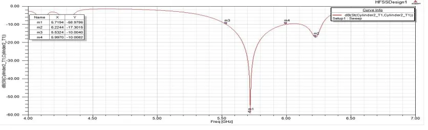
After calculating, optimization and parametric study of Two Parallel Slot Microstrip Antenna over Frequency Selective Surface with Jerusalem Cross components using High Frequency Structural Simulator (HFSS) software with version 13 respectively. We have obtained S-parametric graph versus frequency of this antenna system in figure 4 with the value S-matrix loss at 5.7194 GHz is -58.9786. Return is the loss of power which is due to mismatching of the transmission line or feed point. The accepted value of the return loss for patch antenna is less then -10dB because on above power losses are more, but in the obtained result it is -58.97dB. Which shows matching of feed is proper to its approximate value. And hence we can operate this patch antenna within range of 5.5324 GHz to 5.9970 GHz.
Return loss occur just because of the Reflection due to the mismatching of source to load. As the return loss increases in negative, it shows the matching is improving at the resonant frequency.
The obtained bandwidth is 8.62% over the range of 5.5324 GHz to 5.9970 GHz .
Figure 4. S₁₁ Characteristics of antenna
ISSN(Online): 2320-9801 ISSN (Print) : 2320-9798
I
nternational
J
ournal of
I
nnovative
R
esearch in
C
omputer
and
C
ommunication
E
ngineering
(An ISO 3297: 2007 Certified Organization)
Vol. 4, Issue 2, February 2016
Figure 5. Comparison of optimized gain versus Frequency
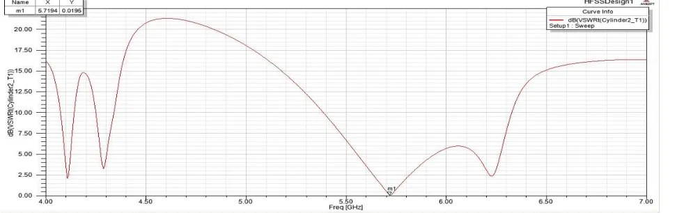
For voltage standing wave ratio of reflected wave upon incident wave shown in figure 6. It is acceptable value for patch antenna is generally in of 0 to 2 but it will be as lower as possible. Here, we observed the value of VSWR is 0.0195 for resonant frequency is 5.8 GHz which shows the proper matching between JC-FSS and Microstrip patch, it is much desirable for any antenna operation.
Figure 6. VSWR graph for JC-FSS over ground plane versus frequency.
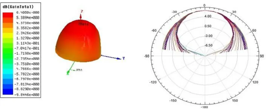
Radiation pattern is a 3D representation in spherical co-ordinates system.this radiation pattern shows the direction where it give the radiation ( in X,Y and Z direction or omni directional) and maximum value of gain by formula 10log₁₀
ISSN(Online): 2320-9801 ISSN (Print) : 2320-9798
I
nternational
J
ournal of
I
nnovative
R
esearch in
C
omputer
and
C
ommunication
E
ngineering
(An ISO 3297: 2007 Certified Organization)
Vol. 4, Issue 2, February 2016
Figure 7. Radiation in 3D with peak gainFigure 8. Radiation pattern
The 2D representation of radiation pattern is also given in which we ind that there is no radiation in the back direction which shows no front to back ration is applicable.
VI. PARAMETRIC SPECIFICATION
Here, parameters are optimized which are obtained after simulation of this structure i.e. shows the peak realized gain is 4.3702, incident power is about 0.0096949 W, radiated power is 0.009431 W, accepted power is 0.0095611 W, Max U or radiatio intensity of antenna is about 0.003325 W/Sr and the efficiency is very good about 98.639% in table 1 below and it is very use full for every antenna system.
Quantity Value Units
Max U 0.003325 W/sr Peak Directivity 4.4305
Radiated Power 0.009431 W Accepted Power 0.0095611 W Incident Power 0.0096949 W VSWR 0.0195
Peak Gain 4.3702 Efficiency (ȵ ) 0.98639
Table 1:Parametric specificaton
ISSN(Online): 2320-9801 ISSN (Print) : 2320-9798
I
nternational
J
ournal of
I
nnovative
R
esearch in
C
omputer
and
C
ommunication
E
ngineering
(An ISO 3297: 2007 Certified Organization)
Vol. 4, Issue 2, February 2016
dielectrics over ground plane for the best impedance matching then the dielectric substrate of 2.2 is used to simulate the antenna results and enhance bandwidth also increase gain of antenna.
In future these antenna parameters can be improved by parametric studies and also improved bandwidth with gain, impedance.
ACKNOWLEDGEMENTS
The authors like to express their special thanks to Mr. Mukesh Kumar (H.O.D, ECE Department) and also thanks to the department of Electronics and Communication Engineering of Apex Institute of Technology, Rampur for their continuous support and encouragement during this work.
REFRENCES
[1] F. Mohamadi Monavar and N. Komjani, “Bandwidth enhancement of microstrip patch antenna using jerusalem cross-shaped frequency selective surfaces by invasive weed optimization approach,”Progress In Electromagnetics Research, Vol. 121, 103-120, 2011.
[2] He, Y., L. Li, C.-H. Liang, and Q. H. Liu, “EBG structures with fractal topologies for ultra-wideband ground bounce noise suppression," Journal of Electromagnetic Waves and Applications, Vol. 24, No. 10, 1365-1374, 2010.
[3] Zhang, J. C., Y. Z. Yin, and J. P. Ma, “Powell optimization of circular ring frequency selective surfaces," Journal of Electromagnetic Waves and Applications, Vol. 24, No. 4, 485-494, 2010.
[4] Yeo, J. and D. Kim, “Novel tapered AMC structures for backscattered RCS reduction," Journal of Electromagnetic Waves and Applications, Vol. 23, Nos. 5-6, 697-709, 2009.
[5] Lin, X. Q., T. J. Cui, Y. Fan, and X. Liu, “Frequency selective surface designed using electric resonant structures in terahertz frequency bands," Journal of Electromagnetic Waves and Applications, Vol. 23, No. 1, 21-29, 2009.
[6] Sievenpiper, D., L. Zhang, R. F. J. Broas, N. G. Alexopolous, and E. Yablonovitch, “High-impedance electromagnetic surfaces with a forbidden frequency band," IEEE Trans. Microw. Theory Tech., Vol. 47, No. 11, 1999.
[7] Luo, G. Q., W. Hong, H. J. Tang, J. X. Chen, X. X. Yin, Z. Q. Kuai, and K. Wu, “Filtenna consisting of horn antenna and substrate integrated waveguide cavity FSS," IEEE Transactions on Antennas and Propagation, Vol. 55, 92-98, Jan. 2007.
[8] Chen, H. Y., Y. Tao, K. L. Hung, and H. T. Chou, “Bandwidth enhancement using dual-band frequency selective surface with Jerusalem cross elements for 2.4/5.8 GHz WLAN antennas," IEEE International Conference on Wireless Information Technology and Systems (ICWITS), 2010.
[9] Hiranandani, M. A., A. B. Yakovlev, and A. A. Kishk, “Arti¯cial magnetic conductors realized by frequency-selective surfaces on a grounded dielectric slab for antenna applications," IEE Pro. Microw. Antennas Propagat., Vol. 153, No. 5, 487-493, Oct. 2006.
[10] Liang, J. and H. Y. D. Yang, \Radiation characteristics of a microstrip patch over an electromagnetic bandgap surface," IEEE Transactions on Antennas and Propagation, Vol. 55, No. 6, 1691-1697, Jun. 2007.
[11] Mallahzadeh, A. R., S. Es'haghi, and A. Alipour, “Design of an E-shaped MIMO antenna using IWO algorithm for wireless application at 5.8 GHz," Progress In Electromagnetics Reseach, Vol. 90, 187-203, 2009.
[12] Mallahzadeh, A. R., H. Oraizi, and Z. Davoodi-Rad, “Application of the invasive weed optimization technique for antenna configurations," Progress In Electromagnetics Research, Vol. 79, 137-150, 2008.
[13] Bahreini, B., A. R. Mallahzadeh, and M. Soleimani, “Design of a meander-shaped MIMO antenna using IWO algorithm for wireless applications," Applied Computational Electromagnetics (ACES), Vol. 25, No. 7, 631-638, Jul. 2010.
[14] Mosallaei, H. and K. Sarabandi, “Antenna miniaturization and bandwidth enhancement using a reactive impedance substrate,"IEEE Transactions on Antennas and Propagation, Vol. 52, 2403-2414, Sep. 2004.
[15] Yang, F. and Y. Rahmat-Samii, “Reflection phase characterizations of the EBG ground plane for low profile wire antenna applications," IEEE Transactions on Antennas and Propagation, Vol. 51, 2691-2703, Oct. 2003.
[16] Qu, D., L. Shafai, and A. Foroozesh, “Improving microstrip patch antenna performance using EBG substrates," IEE Proc. Microw. Antennas Propag., Vol. 153, No. 6, Dec. 2006.
[17] Abedin, M. F., M. Z. Azad, and M. Ali, “Wideband smaller unit-cell planar EBG structures and their application," IEEE Transactions on Antennas and Propagation, Vol. 56, 903-908,Mar. 2008.
[18] Mittra, Y. R. and S. Chakravarty, “A GA-based design of electromagnetic bandgap (EBG) structures utilizing frequency selective surfaces for bandwidth enhancement of Microstrip antennas," IEEE Antennas Propag. Soc. Int. Symp., 400-403, San Antonio, TX, 2002.
BIOGRAPHY
Ms. Geeta, She is M.Tech by Qualification and currently working as Assistant Professor cum Coordinator at Apex Institute of Technology, Rampur, Uttar-Pradesh, Her area of interest is microwave, antenna designing and radar system. She has published two Paper in International Journals. She has attended two national conferences.
Amit Kirti Saran presently studying B.Tech degree in Department of ECE, under APJ Abdul Kalam Technical University at Apex Institute of Technology, Rampur, Uttar-Pradesh, India. His research interest research areas include Antennas, Communication systems and Embedded System. He has published one Paper in International Journals.