Design of a Step-Up Interleaved Boost
Converter with Fuzzy Controller
Anwishta Saha
1, Goutam Kumar Panda
2Pradip Kumar Saha
3PG Student [Power Electronics and Drives], Dept. of EE, Jalpaiguri Govt. Engineering [Autonomous] College, Jalpaiguri, India.1
Professor & HOD, Dept. of EE, Jalpaiguri Govt. Engineering [Autonomous] College, Jalpaiguri, India.2 Professor, Dept. of EE, Jalpaiguri Govt. Engineering [Autonomous] College, Jalpaiguri, India.3
ABSTRACT: Generally conventional boost converters have been used to obtain higher output voltage than the input voltage. When these boost converters are operated for high ratios it leads to high voltage and current stress on the switch. Hence an interleaving technique of boost converter has been presented. This method of approach can be used in high power applications to produce high voltage gain when compared to the conventional boost converter.
This project report deals with the simulation of Interleaved Boost Converter (ILBC). It is seen that, for higher power applications, more modules can be paralleled to increase the power rating and the dynamic performance. One of the challenges in designing a boost converter for high power application is how to handle the high current at the input side. In this project report an interleaved boost dc-dc converter is proposed for current sharing on high power application. Moreover, this converter also reduces the ripple of voltage. The simulated results are presented with R load.
KEYWORDS:Boost converter, Closed loop control, Open loop control, Interleaved, Ripple reductions.
I.INTRODUCTION
desirable for energy dissipation [7]. Therefore, the converter reliability and efficiency can be improved significantly. In this project report, comprehensive simulation analyses are presented to illustrate the performance of the interleaved boost dc-dc converter. The features of the interleaved boost dc-dc converter, the principle of operation and the design procedure are discussed in this project report. The simulation and experimental results are presented. The proposed converter is the parallel of the boost converters and their gate signals are generated by fuzzy controller and this makes the operation more accurate. Moreover, by establishing the fuzzy controller for the interleaved converter can further reduce the size and cost[8]. This work proposes simulation and model for closed loop control system.
II.INTERLEAVED BOOST CONVERTER
In case of boost converter ripple is present in the input current due to rise and fall of inductor current. This problem can be eliminated by using interleaved boost converter .This technique consists of a phase shifting of the control signals of cells in parallel operating at the same switching frequency. The main advantage are the current distribution .The current in the switches are just a function of the input current .So interleaved boost converters can reduce input current ripple and the switching losses.
III.ILBC OPERATING PRINCIPLE
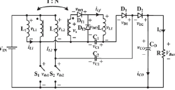
The proposed interleaved converter topology with high voltage transfer ratio is proposed as shown in Fig.1. The proposed converter consists of two-phase circuits with interleaved operation. The first phase is a boost integrating the forward-type circuit structure, which includes inductor L1 and switch S1 for the boost and an isolated forward energy-delivering circuit with turn ratio N. The second phase of the proposed converter is a boost circuit which contains inductor L2, switch S2, blocking capacitor C2, and diode D2 followed by the common output capacitor Co. From Figure.1, one can see that the proposed converter is basically based on the conventional voltage-doubler for the second phase circuit. However, for the first phase, in order to reduce the voltage stress of switch S1 and diode D1, an additional blocking capacitor C1, is added to function as that of C2 for the second phase. The operation principle can be described by considering the key waveforms of the proposed converter as shown in Figure.2. For simplicity, assume that all the components in Figure.1 including the high-frequency transformer of the forward energy delivering circuit are assumed ideal and under steady-state condition.
Figure.2: Key waveforms of the proposed converter.
IV.MODES OF OPERATION
Mode 1 [t0 < t ≤ t1]: From Fig. 2, one can see that for mode 1, switches S1, S2 are turned on. Diode Df1 is forward biased, while diodes D1,D2,Df2 are reverse biased. During this operation mode, both iL1 and iL2 are increasing to store energy in L1 and L2, respectively. Meanwhile, the input power is delivered to the secondary side through the isolation transformer and inductor Lf to charge capacitor C1. Also, the output power is supplied from capacitor Co. The voltage across inductances L1 and L2 can be represented as follows:
𝐿1𝑑𝑖𝐿1
𝑑𝑡 = 𝐿2
𝑑𝑖𝐿2
𝑑𝑡 = 𝑉𝐼𝑁
Mode 2 [t1 < t ≤ t2]: For this operation mode, switch S1 remains conducting, and S2 is turned off. Also, diodes D1 andDf2 remain reverse biased; D2 and Df1 are forward biased. The energy stored in inductor L2 is now released through C2 and D2 to the output. However, the first phase circuit including the forward-type converter remains the same. The voltage across inductances L1 and L2 can be represented as the following:
𝐿1𝑑𝑖𝐿1
𝑑𝑡 = 𝑉𝐼𝑁
𝐿2𝑑𝑖𝐿2
𝑑𝑡 = 𝑉𝐼𝑁 + 𝑣𝑐2 − 𝑉𝑏𝑢𝑠
𝐿1𝑑𝑖𝐿1
𝑑𝑡 = 𝐿2
𝑑𝑖𝐿2
𝑑𝑡 = 𝑉𝐼𝑁
Mode 4 [t3 < t ≤ t4]: During this operation mode, S1 is turned off, and S2 is turned on. Diode D2 and Df1 are reverse biased, and diode D1 is forward biased. Since diode Df1 is reverse biased, diode Df2 must turn on to conduct the inductor current iLf.. The energy stored in L1 is now released through C1 and D1 to charge capacitor C2 for compensating the lost charges in previous modes. The energy stored in transformer is now treated to perform the self-resetting operation without additional self-resetting winding. Also, the output power is supplied from capacitor Co. The voltage across inductances L1 and L2 can be represented as follows:
𝐿1𝑑𝑖𝐿1
𝑑𝑡 = 𝑉𝐼𝑁 + 𝑣𝑐1 − 𝑣𝑐2
𝐿2𝑑𝑖𝐿1
𝑑𝑡 = 𝑉𝐼𝑁
V.FUZZY LOGIC CONTROLLER (FLC) DESIGN
The block diagram of fuzzy logic controller (FLC) is shown in fig.3. It consists of three main blocks: fuzzification, inference engine and defuzzification. Thetwo FLC input variables are the error E and change in error E*. Depending on membership functions and therules FLC operates
Figure 3: Block Diagram of FLC. Fuzzification
The membership function values are assigned to the linguistic variables using seventeen fuzzy subsets. Table-I shows the rules of FLC. E and E* are input variables,where E is the error between the reference and actual voltage of the system, E* is the change in error in thesampling interval.
Inference Engine
Mamdani method is used with Max-Min operation fuzzy combination. Fuzzy inference is based on fuzzy rules. Rules are framed in inference engine block. The output membership function of each rule is given by MIN (Minimum) operator and MAX (Maximum) operator.
Defuzzification
The output of fuzzy controller is a fuzzy subset. As the actual system requires a non fuzzy value of Control, defuzzication is required. Defuzzifier is used to convert the linguistic fuzzy sets back into actual value. Table 1 shows the representation of the typical Rule Surface of fuzzylogic controller.
VI.MATLAB SIMULATION
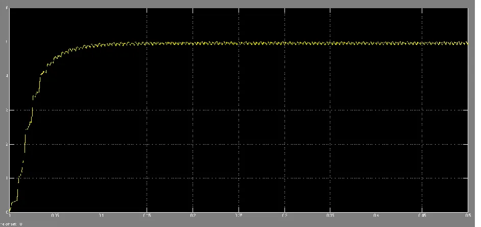
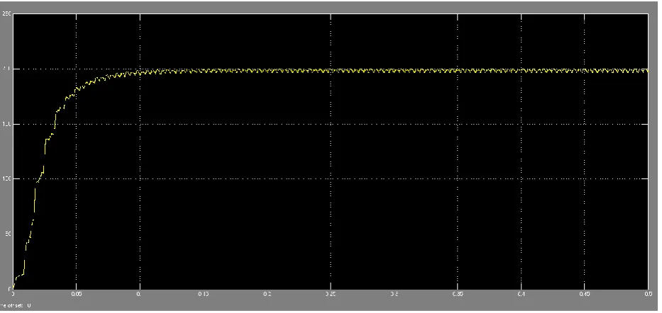
This is the Simulink diagram of interleaved boost converter with R-Load is shown in Fig 4. The voltage and current measurement blocks are connected to measure the output voltage and output current. The scopes are connected to measure the driving pulse and voltage across the switch. DC input voltage 24v DC is shown in the Figure 5. The gating pulse across the switch is shown in Fig.6. The output current is 5Amps and output voltage is 200V DC is shown in the Fig.7. and Fig.8.
Figure 4: Simulation Circuit Diagram of ILBC with R-load Using Fuzzy controller
Here the filter capacitor is used to reduce the ripples of the output voltage. The simulation result is given below:
Figure 6: Switching Pulse
Figure 8: Output Voltage Waveform
VII.RESULTS
After simulation of conventional boost converter and interleaved boost converter we get this results is given below in table 2.
Boost Type Vin Iin Pin Vout Iout Pout Efficiency
Interleaved(FUZZY) 24 54.5 1308 200 5 1000 76.5%
Table 2. Simulation Parameters Value
For different types of load calculating ripple factor with FUZYY controller we get .
Load R =38ohm,
Iin(rf)= 1.046491721, Io(rf)= 1.000012724, Vo(rf)= 1.000012724
Load R =40ohm,
Iin(rf)= 1.046741888, Io(rf)=1.000011599 , Vo(rf)=1.000011599
Load R =42ohm,
Iin(rf)= 1.047503097, Io(rf)= 1.000010523, Vo(rf)= 1.00001052
VIII.CONCLUSION
IX.FUTURE SCOPE
A step-up interleaved boost converter has been simulated in this paper with PI and fuzzy logic control can be simulated with different types of feedback control like genetic algorithm ,artificial neural network and others can be used for power quality improvement or to get better efficiency advanced tuning and to check the constant output voltage with least ripple and to support different appliances with different voltage ratings.
Further this simulation model can be hardware implemented for practical output.
REFERENCES
[1] M.Subramani, Mr.K.Karthikeyan (2014) ― An Interleaved Boost DC-DC Converter for High Voltage AC and DC Applications, IJAREEIE, Vol 3, Issue 4, April 2014.
[2] R.N.A.L. Silva, G.A.L. Henn, P.P. Praca, L.H.S.C. Barreto, D.S. Oliveira Jr., F.L.M. Antunes (2008) ― Soft Switching Interleaved Boost Converter with High Voltage Gain, IEEE, 2008.
[3] Ching-Ming Lai, High-Efficiency Modular High Step-Up Interleaved Boost Converter for DC-Microgrid Applications, IEEE, Vol 48, No. 1, JANUARY/FEBRUARY 2012, Member, IEEE, Ching-Tsai Pan, Member, IEEE, and Ming-Chieh Cheng, Student Member, IEEE.
[4] S.NANGENDRA KUMAR, CHASSAN (2014) ― Modeling and Simulation of Closed Loop Control of High Voltage Gain Interleaved DC/DCConverter for RES Application, IJPSOEM, Vol 4, Issue 3, 2014.
[5] P.Radika, J.Baskaran, A.Nandhini (2014) ― High Voltage Gain Interleaved Boost Converter, IJAREEIE, Vol 3, Issue 1, January 2014.
[6] Fariborz Musavi, Member IEEE (2011) ―A High-Performance Single Phase Bridgeless Interleaved PFC Converter for Plug-in Hybrid Electric Vehicle Battery Chargers, IJAREEIE, Vol 47, NO 4, July/August 2011.
[7] Dong Wang, Yan Deng, Xiangning He, Senior Member, IEEE(2008) ― Designing and Analysis of an Interleaved Boost Converter with Passive Lossless Clamp Circuits , IEEE, 2008.
[8] Gaurav, Amrit Kaur, Comparison between Conventional PID and Fuzzy Logic Controller for Liquid Flow Control: Performance Evaluation of Fuzzy Logic and PID Controller by Using MATLAB/Simulink, International Journal of Innovative Technology and Exploring Engineering (IJITEE) ISSN: 2278-3075, Volume-1, Issue-1, June 2012