Automation System for Humidity Using FPID
Godhini Prathyusha
1Research Scholar, Department of Instrumentation & USIC, S. K .University, Anantapur, Andhra Pradesh, India
ABSTRACT: The objective of this paper is to develop automation system for humidity implementing software Fuzzy
with PID control algorithm (FPID).Now a day’s controlling of process parameters in industrial application and other appliances plays a vital role among them one of the most critical and important parameter is humidity. For this relative humidity can be maintained constant continuously in required applications at constant temperature. Using Arduino mega2560 microcontroller [1] implementing FPID [2] for controlling the humidity control. The present work is prosed to implement the software program code for FPID control logic for reducing the hardware complexity in processing software using java programming language.In earlier works it is implemented by using inbuilt logics available in some software applications like MATLAB and LABVIEW.
KEYWORDS:HRT-393 humidity sensor, FPID, DC motor, Arduino mega2560 microcontroller.
I. INTRODUCTION
The amount of water vapour found in air can vary dramatically, from almost zero to the point of saturation. Insufficient or excessive humidity, or swings between the two, can damage sensitive materials and objects. Humans are also sensitive to humid air, and high humidity can cause discomfort. The human body uses evaporative cooling as its primary mechanism for regulating temperature. When the relative humidity is high, the rate of perspiration evaporating from the skin decreases because the amount of water vapour in the air is already close to saturation. Humans feel the rate of heat transfer from the body rather than temperature itself. we feel warmer when the relative humidity is high. When humidity is so high that perspiration cannot easily evaporate, the body may overheat, causing discomfort. A combination of high temperature and low relative humidity allows more effective cooling. Traditionally, many environments have been controlled based solely on measurements of temperature. In recent years, the measurement of humidity has become equally important. Humidity control is especially important in living, storage and manufacturing sites. Control of temperature and relative humidity is also critical in the preservation of many materials including medications, foods, fabrics and wood products.
Unacceptable humidity levels, especially when combined with temperature extremes, contribute significantly to the breakdown of materials. Heat accelerates deterioration, and high relative humidity provides moisture, which promotes harmful chemical reactions. When combined, these factors can encourage insect activity and the growth of mold. Extremely low relative humidity can also have damaging effects, desiccating sensitive materials and causing them to become brittle. Large fluctuations in temperature and relative humidity also cause damage through expansion and contraction, which helps accelerate deterioration.
Installation and operation of adequate climate controls to meet preservation standards will retard the deterioration of materials considerably. To control humidity and prevent damage or discomfort or to detect events that may have led to product damage in storage or transit, accurate measurement of humidity is vital and, ideally, must be available in a component form that enables easy, cost-effective integration with electronic controls.
II. PROCEDURE
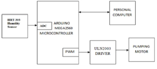
in the air, at a specific air temperature, expressed as a percentage of the maximum amount of water the air can hold at that temperature. According to the measurement units, humidity sensors are divided into two types: Relative humidity (RH) sensors and absolute humidity (moisture) sensors. Relative humidity sensors are classified into ceramic, semiconductor, and polymer humidity sensors. Ceramic Sensing Material, humidity sensors based on water-phase protonic ceramic materials are used widely in industry and research laboratories.The adsorbed water condensed on the surface of the materials and protons will be conducted in the formed aquatic layers.For ionic sensing materials, if the humidity increases, the conductivity decreases and the dielectric constant increases.Detecting the relative humidity by using HRT-393 humidity sensor,it is a resistive based sensor and it gives output as voltage for appropriate relative humidity value at fixed temarature 30OC .The block diagram of total system as shown in Fig. 1.
FIG. 1 Block diagram for humidity control
HRT-393 Humidity Sensor working principle is explained in FIG. 3.It is resistive type humidity sensor.
FIG. 2 Humidity Sensor FIG. 3 Principle of humidity sensor
motor is used based on the humidity value the water pumped in to a closed container where the humidity control is required.
The FPID algorithm involves the both technical aspects of Fuzzy logic and PID control, implanting software algorithm for reducing the hardware complexity and improve the system reliability. The controlling technique fuzzy includes the three steps, they are fuzzification , rule set and defuzzzification .The fuzzification [5] determines the input linguistic variables for required control and the fuzzy rule set can be determined with the drive value s of PWM of microcontroller which used the technique is PID control and finally the defuzzification step is represents the PWM output drive percentage with respect to the PID [6] control determined in rule set.
The fuzzification represents in the form of membership function of input linguistic variables based on the error Membership Functions for F (humidity) = { Very low, Low, Medium, High, Very high}
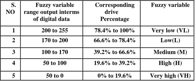
Table 1 . Fuzzification
The Table 1. Shows the the fuzzy variables are intialised to crisp input range of present work and it explains the functioning of humidity control. It is one of the most important part in fuzzification.
S. NO
Fuzzy variable range output interms
of digital data
Corresponding drive
Percentage
Fuzzy variable
1 200 to 255 78.4% to 100% Very low (VL)
2 170 to 200 66.6% to 78.4% Low(L)
3 100 to 170 39.2% to 66.6% Medium (M)
4 50 to 100 19.6% to 39.2% High (H)
5 50 to 0 0% to 19.6% Very high (VH)
Table 2 .Defuzzifiation
S. NO
Crisp input range (error= set value -measured value)
Fuzzy variable
1 0 to 30 Very low (VH)
2 20 to 40 Low (L)
3 30 to 50 Medium (M)
4 50 to 70 High (H)
The Table 2. Shows the deffuzification process ,in it based on the fuzzy variable the output of the PWM of microcontroller is determined interms of output fuzzy variable and also corresponding drive percentage.
III.EXPERIMENTAL RESULTS
The snapshot and the GUIs shows the results of automaton system for humidity implementing FPID.
FIG. 4 Snap shot for humidity control
The FIG. 5 GUI represents the set value and the measured value ,the total system photograph ,slides for both set and measured values with the controlling buttons and the graph plot real time versus relative humidity.
IV. CONCLUSION
We have implemented an automatic humidity system implementing software FPID control for reducing the complexity of hardware and reliability of system. Our algorithm successfully detects the relative humidity and controls with less response time as well as settling time and steady state error. We have successfully experiment this system in lab and therefore proposed a web based humidity monitoring and controlling network with flexibility, further extension of this system is to control from any place via internet even with different type of devices. This could have a substantial benefit from this research work for efficient management of humidity.
REFERENCES
[1] A. Prodic, D. Maksimovic, “Design of a digital PID regulator based on look-up tables for control of high-frequency dc–dc converters”, iProceedings of IEEE Workshop on Computers in Power Electronics, 2002, pp. 18–22.
[2] Ardehali MM, Saboori M, Teshnelab M. “Numerical simulation and analysis of fuzzy PID and PSD control methodologies as dynamic energy efficiency measures” , Energy Convers Manage 2004;45(13–14):1981–92.
[3] Tzafestas S, Papanikolopoulos NP, “ Incremental fuzzy expert PID control” , IEEE Trans Ind Electron 1990;37(5):365–71. [4] M. Bertalmio, G. Sapiro, V. Caselles, and C. Ballester, “Image inpainting”, Proc. SIGGRAPH, pp. 417–424, 2000.
[5] A. Criminisi, P. Perez, and K. Toyama, “Region filling and object removal by exemplar-based image inpainting.”, IEEE Transactions on Image Processing, vol. 13, no.9, pp. 1200–1212, 2004.
[6] FarhadAslam and GagandeepKaur, March 2011 "Comparative Analysis of Conventional, P, PI, PID and Fuzzy Logic Controllers for the Efficient Control of Concentration in CSTR", International Journal of Computer Applications, Vol.17, No.6, pp.12-16.