© 2015, IRJET.NET- All Rights Reserved
Page 1682
Comparative Study of Topological Optimization of Beam and Ring Type
Structures under static Loading Condition
Vani Taklikar
1, Anadi Misra
2P.G. Student, Department of Mechanical Engineering, G.B.P.U.A.T, Pantnagar, Uttarakhand, India
Professor, Department of Mechanical Engineering, G.B.P.U.A.T, Pantnagar, Uttarakhand, India
Abstract- We present ANSYS based Optimality Criterion approach for topology optimization of beam and ring type structures. Optimality Criterion is to be very efficient for solving the topology optimization problem. The optimization problem is formulated as to minimize the material compliance under volume constraints. Two linear elastic isotropic structures have been studied. These structures have been studied by using finite element solver software ANSYS. ANSYS employs topology optimization using the Solid Isotropic Material with Penalization (SIMP) scheme for the penalization of the intermediate design variables and the Optimality criterion for updating the design variables. All the
structures have been optimized for minimum
compliance and then other parameters like-stresses, displacement in x-y directions, von misses stress, deformed and un-deformed shapes are obtained. Further the structures have been studied by changing material from isotropic to orthotropic and then the results obtained by both the materials have compared.
Keywords: ANSYS, Optimality criterion approach,
Compliance
1. INTRODUCTION
In the present scenario, topology optimization is the most important structural optimization which gives the best distribution of material at the conceptual level. In topology
optimization the optimal layouts are generated
automatically to solve the design problems in the field of engineering. Optimization is the process of finding for feasible solution in a problem until no other best suitable solution can be found. In general, optimization is the process of minimization or maximization of an objective function subjected to given constraints (stress, deflection etc.) for the problem to be solved. In optimization, all the results obtained by all the candidates are compared and the best optimum result is obtained.
Topology optimization is concerned with seeking the optimum distribution of material in a given design domain
that minimizes a given cost function while satisfies a series
of constraints [1].
There are many topological optimization methods have been developed some of which are homogenization method, evolutionary structural optimization (ESO) method, solid isotropic method with penalization (SIMP) and other methods. In topology optimization there are mainly two types of regions, one is solid other is void. Solid region means the region with material and the void region means the region without material. Topology optimization gives the best suitable use of material over the structure or body such that an objective function (i.e. is to be maximized or minimized) subjected to given constraint should be satisfied.
The development of topological optimization can be attributed to Bendsoe and Kikuchi [2]. They assumed that the structure is formed by a set of non-homogenous elements which are composed of solid and void regions. They obtained optimal design under volume constraint through optimization process. This method requires a large amount of variables. To overcome this difficulty Bendsøe [9] introduces a solid isotropic material
penalization. Suzuki et al. [3] studied the shape and
topology optimization of linearly elastic material. Author done some modifications in the homogenization method and also clarified the strength of the present approach for plane structure. An evolutionary structural optimization
(ESO) technique introduced by Xie et al. [7] in which
material are gradually introduced or removed until the best condition is met. But once the material is removed it is not introduced again in the structure and this is the drawback of ESO technique. This difficulty was overcome by bi-directional evolutionary structural optimization
(BESO) introduced by Querin et al.[8]. Many approaches
have been studied to solve numerical instability. Further genetic algorithm, optimality criteria, adaptive refinement approach etc. have been developed by many researchers.
© 2015, IRJET.NET- All Rights Reserved
Page 1683
isotropic and orthotropic material structures and then theresults obtained by both the material have been compared.
2. THE OPTIMALITY CRITERION APPROACH
Optimality criteria are necessary conditions for minimality of the objective function and these can be derived by using either variational methods or extremum principles of mechanics. Optimality criteria (OC) method
was analytically formulated by Prager and co-workers in
1960. It was later developed numerically and become a
widely accepted structural optimization method (Venkaya et al. 1968).
The discrete topology optimization problem is
characterized by a large number of design variables, N in this case. It is therefore common to use iterative optimization techniques to solve this problem, e.g. the method of moving asymptotes optimality criteria (OC) method, to name two. Here we choose the latter. At each iteration of the OC method, the design variables are updated using a heuristic scheme.
The Lagrangian for the optimization problem is defined as:
Where, , , , and are Lagrange multipliers for the
various constraints. The optimality condition is given by:
Now, Compliance,
Differentiating eq. 3.8 w. r. t. , the optimality condition
can be written as:
The Compliance sensitivity can be evaluated as using eq. :
Based on these expressions, the design variables are
iteration step determined from the equilibrium equations.
3. NUMERICAL EXAMPLES
In this section two example of optimization with pressure load and two example of optimization with point load are given. In these examples, all the four structures were solved by taking different isotropic properties for all the structures like, Young’s modulus and Poisson’s ratio and then all the four structures were solved for orthotropic material by taking Young’s modulus 201GPa, 21.7GPa, 21.7GPa, Poisson’s ratio 0.17 respectively and shear modulus 5.4GPa in all the direction respectively. For all the examples, volume usage fraction is 50% and a fixed mesh of 8-node quadrilateral element is used, the thickness of the structures is 1 mm and the convergence criteria are taken 0.0001.
3.1 Example 1
© 2015, IRJET.NET- All Rights Reserved
Page 1684
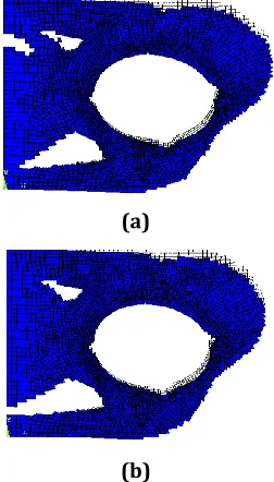
solution obtained by proposed method is presented inFig.1.2 (a) and (b). There is no checkerboard problem in the solution. The iteration histories for 50% volume fraction are presented in Fig. 1.3. The objective function decreases steadily and converges to 48.204 after 32 iterations for isotropic material and 48.798after 37 iterations for orthotropic material.
Fig.1.1 Geometry and boundary condition of overhanging beam
(a)
(b)
Fig. 1.2 Optimized shape for (a) Isotropic material (b) Orthotropic material
(a)
(b)
Fig. 1.3 Compliance v/s Iteration for overhanging beam (a) Isotropic (b) Orthotropic
After obtaining compliance and optimal shape we have obtained von misses stress. At the point of loading maximum stress occurred. Optimized structures for both the materials with von misses stress have shown in the Fig.1.4 (a) and (b) respectively. Maximum stress for
isotropic material is 20814N/mm2 and for orthotropic
material is 12299N/mm2. Now the deformed and
un-deformed (initial structure) shape is shown in the Fig.1.5 (a) and (b) respectively below. The black portion shows the un-deformed structure and the blue portion shows the deformed structure of the beam.
(a)
(b)
Fig. 1.4 Von misses stress induced in structure for (a) Isotropic (b) Orthotropic
6mm
© 2015, IRJET.NET- All Rights Reserved
Page 1685
(a)(b)
Fig. 1.5 Deformed and un-deformed shape obtained for (a) Isotropic (b) Orthotropic
3.2 Example 2
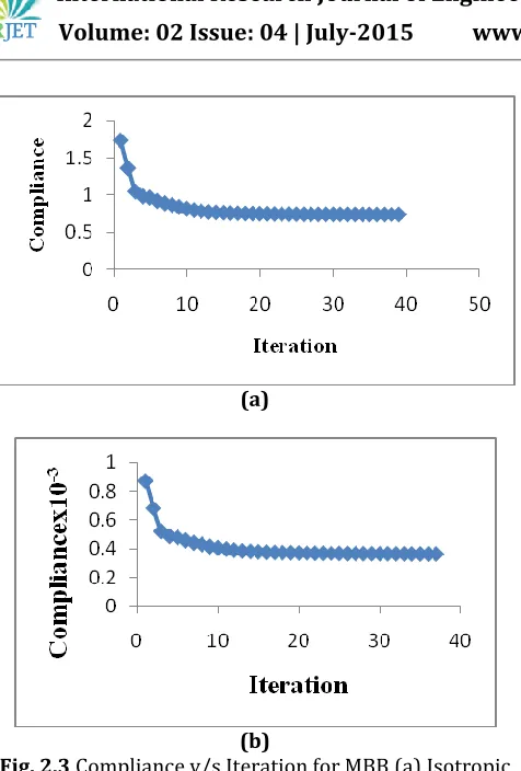
A half ring of 10 mm outer and 3 mm inner radius is considered. The ring is subjected to pressure load of 1 N/mm and the geometry is shown in the Fig.1.6. Young’s modulus is 1000 Pa and Poisson’s ratio is 0.3. The design domain is descretized into 7381 elements. The optimal solution obtained by proposed method is presented in Fig.1.7 (a) and (b) respectively. There is no checkerboard problem in the solution. The iteration histories for 50% volume fraction are presented in Fig. 1.8 (a) and (b) respectively. The objective function decreases steadily and converges to 3.8219 after 31 iterations for isotropic material and 0.01899 after 34 iterations for orthotropic material.
Fig.1.6 Geometry and boundary condition of overhanging beam
(a)
(b)
Fig. 1.7 Optimized shape for (a) Isotropic material (b) Orthotropic material
(a)
(b)
Fig. 1.8 Compliance v/s Iteration for Half ring (a) Isotropic (b) Orthotropic
After obtaining compliance and optimal shape we have obtained von misses stress. Near the boundary condition maximum stress occurred. Optimized structures for both the materials with von misses stress have shown in the Fig.1.9 (a) and (b) respectively. Maximum stress for
isotropic material is 34.338 N/mm2 and for orthotropic
material is 13.273 N/mm2. Now the deformed and
un-R=10mm
mmm r=3mm
© 2015, IRJET.NET- All Rights Reserved
Page 1686
deformed (initial structure) shape is shown in the Fig. 2 (a)and (b) respectively. The black portion shows the un-deformed structure and the blue portion shows the deformed structure of the beam.
(a)
(b)
Fig.1.9 Von misses stress induced in structure for (a) Isotropic (b) Orthotropic
(a)
(b)
Fig. 2 Deformed and un-deformed shape obtained for (a) Isotropic (b) Orthotropic
3.3 Example 3
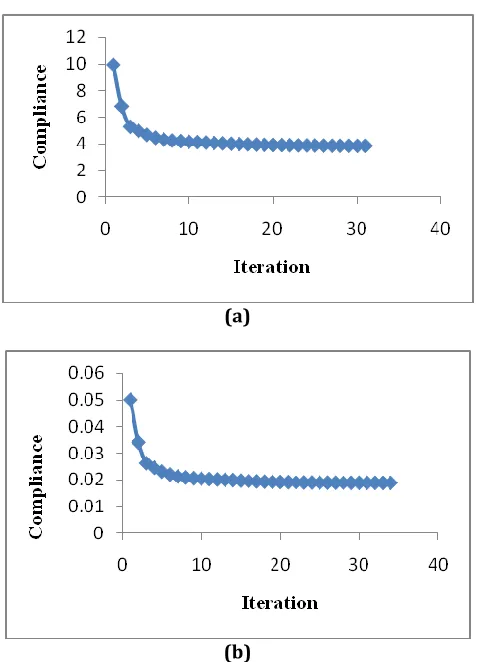
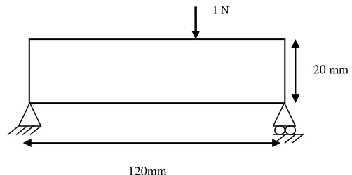
A Messerschmitt Bolkow Blohm (MBB) beam is considered. The beam is subjected to point load of 1 N and the geometry is shown in the Fig.2.1 Young’s modulus is
100 Pa and Poisson’s ratio is 0.3. The design domain is descretized into 1281 elements. The optimal solution obtained by proposed method is presented in Fig.2.2 (a) and (b) respectively. The iteration histories for 50% volume fraction are presented in Fig. 2.3 (a) and (b) respectively. The objective function decreases steadily and converges to 0.74065 after 39 iterations for isotropic material and 0.00036629 after 37 iterations for orthotropic material.
Fig.2.1 Geometry and boundary condition of overhanging beam
(a)
(b)
Fig. 2.2 Optimized shape for (a) Isotropic material (b) Orthotropic material
20 mm
120mm
© 2015, IRJET.NET- All Rights Reserved
Page 1687
(a)(b)
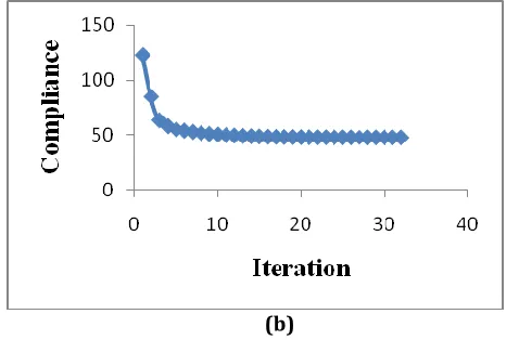
Fig. 2.3 Compliance v/s Iteration for MBB (a) Isotropic (b) Orthotropic
Now the von misses stress have calculated. At the point of loading maximum stress occurred. Optimized structures for both the materials with von misses stress have shown in the Fig.2.4 (a) and (b) respectively. Maximum stress for
isotropic material is 2.351 N/mm2 and for orthotropic
material is 0.86758 N/mm2. Now the deformed and
un-deformed (initial structure) shape is shown in the Fig. 2.5 (a) and (b) respectively. The black portion shows the un-deformed structure and the blue portion shows the deformed structure of the beam.
(a)
(b)
Fig. 2.4 Von misses stress induced in structure for (a) Isotropic (b) Orthotropic
(a)
(b)
Fig. 2.5 Deformed and un-deformed shape obtained for (a) isotropic (b) orthotropic
3.4 Example 4
© 2015, IRJET.NET- All Rights Reserved
Page 1688
Fig.2.6 Geometry and boundary condition of overhangingbeam
(a)
(b)
Fig. 2.7 Optimized shape for (a) Isotropic material (b) Orthotropic material
(a)
(b)
Fig. 2.8 Compliance v/s Iteration for MBB (a) Isotropic (b) Orthotropic
The objective function decreases steadily and converges to 0.11335 after 14 iterations for isotropic material and
0.54588x10⁻⁴ after 14 iterations for orthotropic material.
Now the von misses stress have calculated. Near the point of loading maximum stress occurred. Optimized structures for both the materials with von misses stress have shown in the Fig.2.9 (a) and (b) respectively. Maximum stress for
isotropic material is 2.351 N/mm2 and for orthotropic
material is 0.86758 N/mm2. Now the deformed and
un-deformed (initial structure) shape is shown in the Fig. 3 (a) and (b) respectively. The black portion shows the un-deformed structure and the blue portion shows the deformed structure of the beam.
30 mm 7 mm
© 2015, IRJET.NET- All Rights Reserved
Page 1689
(a)(b)
Fig. 2.9. Von misses stress induced in structure for (a) isotropic (b) orthotropic
(a)
(b)
Fig. 3 Deformed and un-deformed shape obtained for (a) isotropic (b) orthotropic
4. EFFECT OF MESH SIZE/ NO. OF ELEMENTS
ON COMPLIANCE AND TOPOLOGY OBTAINED
4.1 FOR ISOTROPIC MATERIAL OVERHANGING
BEAM WITH UDL
In this section, effect of mesh size on the compliance and topology obtained has been studied for isotropic overhanging beam with UDL. The effect has been studied at the same volume fraction, load, Poisson’s ratio, thickness, Young’s modulus as taken in original model. To examine study the convergence characteristics of the OC in ANSYS, the compliance vs. Iteration plots for different number of elements have been plotted. The Table 1.1 below shows mesh size and compliance values.
Table 1.1: Variation of Compliance with number of elements
Mesh size
Compliance Iterations
120, 20, 0.5
49.777
32
130, 30, 0.5
48.866
31
140, 40, 0.5
48.659
37
150, 50, 0.5
48.204
32
160, 60, 0.5
47.209
30
© 2015, IRJET.NET- All Rights Reserved
Page 1690
Mesh size 120, 20Mesh size 130, 30
Mesh size 140, 40
Mesh size 150, 50
Mesh size 160, 60
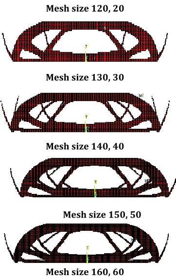
Fig. 3.1 Optimal topologies for different mesh densities for IM Model 5 (
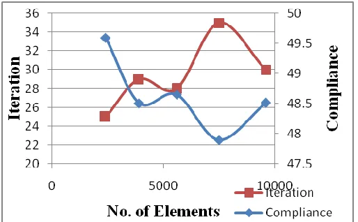
Fig. 3.2 Effect of number of elements on compliance and iterations for Isotropic material Model 5
4.2
FOR
ORTHOTROPIC
MATERIAL
OVERHANGING BEAM WITH UDL
In this section, effect of mesh size on the compliance and topology obtained has been studied for Overhanging beam
with UDL of orthotropic structures. The effect has been studied at the same volume fraction, Poisson’s ratio, Thickness, Young’s modulus. To examine study the convergence characteristics of the OC in ANSYS, the compliance vs. Iteration plots for different number of elements have been plotted.
The Table 1.2 below shows mesh size and compliance values.
Table 1.2: Variation of Compliance with number of elements for OM Model 5
Mesh size Compliance Iterations
120, 20, 0.5 49.596 25
130, 30, 0.5 48.509 29
140, 40, 0.5 48.651 28
150, 50, 0.5 47.898 35
160, 60, 0.5 48.513 30
For Overhanging beam with UDL values of compliance is varying as the number of elements are increasing. Here the value of compliance increases from 49.596 N-mm again it decreases to 48.509 mm and then increases to 48.651 N-mm and further decreases to 47.898 N-N-mm and then increases to 48.513N-mm. It is observed from Fig.3.3 that the final optimal topology in each case is different and as the elements number is increased the optimal shape is much more finer then the previous one. It is observed that convergence rates are also random in nature for mesh size 120, 20 it takes 25 iterations to converge while it comes down to 29 iteration for mesh size 130, 30 and is again increased to 35 and 30 iterations for mesh size 150, 50 and 160, 60 respectively. The iteration histories for 50% volume as shown in Fig. 3.4
© 2015, IRJET.NET- All Rights Reserved
Page 1691
Mesh size 130, 30Mesh size 140, 40
Mesh size 150, 50
Mesh size 160, 60
Fig. 3.3 Optimal topologies for different mesh densities for Orthotropic material Model 5 (
Fig. 3.4 Effect of number of elements on compliance and iterations for Orthotropic material Model 5
CONCLUSION
In the present paper, the topology optimization of structures which are subjected to pressure load and point load is solved by using an optimality criterion approach. Minimum compliance problem for optimization is considered. In this work, a commercially available finite element solver ANSYS 12.0 has been used to determine the optimal topology of the structures. The procedure is
applied to a number of design problems. In all the cases, it is concluded that overall compliance decreases from initial to final value. The comparison of two materials shows that orthotropic materials structures have less compliance value than isotropic material structures in all the cases and that is why have stiffer structures. Von misses stresses are also less in orthotropic material structures than isotropic material structures. Compliance values decreases as the number of iterations increases for every model. As is evident from these plots, most of the compliance is dropped in the earlier iterations. Later on there is little variation in the compliance values.
ACKNOWLEDGEMENT
The author wish to deepest sense of gratitude and veneration to Dr. Anadi Misra (Professor, Department of Mechanical Engineering, G.B.P.U.A.T, Uttaranchal) for suggesting the author to do this work. This work has been partially supported by Mr. Dheeraj Gunwant (Senior student of G.B.P.U.A.T, Uttaranchal) who gave the knowledge of ANSYS software to the author.
REFERENCES
[1] M.P. Bendsoe, O. Sigmund, Topology Optimization: Theory, Methods and Applications, Springer, Berlin, 2003.
[2] Bendsøe, M. P. and Kikuchi, N. 1988. Generating
optimal topologies in structural design using a
homogenization method. Comput. Meth. Appl. Mech.
Eng. 71: 197-224
[3] Suzuki, K. and Kikuchi, N. 1991.A homogenization
method for shape and topology optimization. Comput.
Meth. Appl. Mech. Eng. 93: 291-318
[4] Diaz, A. and Sigmund, O. (1995), “Checkerboard
patterns in layout optimization” Struct.
Optim.. Vol: 10: 40-45
[5] Zhan Kang, Yiqiang Wang, (2011), “Structural topology optimization based on non-local Shepard interpolation of density field”.Comput.Methods Appl. Mech. Eng
[6] Yiqiang Wang, Zhan Kang, Qizhi He,(2014) “Adaptive topology optimization with independent error control for separated displacement and density fields” Comput. And Structures. 135:50-61
[7] Y.M. Xie, G.P. Steven. 1997. Evolutionary Structural
© 2015, IRJET.NET- All Rights Reserved
Page 1692
[8] Querin O.M., Victoria M., Martí P. 2010.Topologyoptimization of truss-like continua with different material properties in tension and compression. Struct Multidiscip Optimiz.42: 25–32.
[9] Bendsoe, M. P. 1989.Optimal shape design as a material distribution problem. Springer- Verlag 1:193- 202
[10] N.P. Garcia-Lopez, M. Sanchez-Silva, A.L.Medaglia, A. Chateauneuf, [2011], “A hybrid topology optimization methodology combining simulated annealing and SIMP. Comp.And Struct.89:1512-1522
[11] Bendsoe M.P, Sigmund O, [2003], “Topology Optimization, theory, methods and applications”. Newyork: Springer.
[12] Rozvany G.A. [2009], “Critical review of established methods of structural topology optimization”. Struct. Multidiscip. Optim. 37:217-37
[13] Tcherniak, D. and Sigmund, O. [2001], “A web-based
topology optimization program”. Struct. Multidisc.
Optim. Springer-Verlag 22: 179-187