FREQUENCY SELECTIVE SURFACES WITH FRACTAL FOUR LEGGED ELEMENTS
J. C. Zhang, Y. Z. Yin, and J. P. Ma
National Laboratory of Antennas and Microwave Technology Xidian University
Xi’an, Shaanxi 710071, P. R. China
Abstract—Frequency selective surfaces (FSSs) with fractal four legged aperture elements are studied. Three different order fractal elements are discussed for comparison. The results show that by using this novel kind of elements, multiband FSSs with miniaturized elements can be achieved. The ratio of the first resonant wavelength to the periodicity can be up to 10.36. Four passbands for normal incidence or two stable passbands for different incident angle and polarizations can be obtained. The FSS is analyzed by the spectral domain approach.
1. INTRODUCTION
Frequency selective surfaces, which are used widely as microwave absorbers [1] and filters [2], have been extensively investigated over the years [3–8]. In many communication situations, multiband FSSs are required. Several techniques for multiband FSSs have been presented in the previous papers: layered FSS [3], perturbation of a single-layered FSS [4], and the use of multiresonant elements such as Sierpinski dipole elements [5], double square loop elements [3] and fractal cross dipole elements [14]. In practice, The FSS with multiresonant elements has the advantages of a lighter structure, a simplified design and ease to fabricate.
In this paper, FSSs with fractal dipole aperture elements are presented. Three different order fractal elements are discussed. The results show that both multiband and miniaturized elements can be effected by using higher order fractal elements.
2. FRACTALS AND THEIR APPLICATIONS
Fractals are geometrical shapes that are self similar, and can generate almost any complex structure in nature, through iterating of certain simple geometries. By using fractal shapes, an arbitrarily long curve confined in a given volume can be obtained. This property has been shown effective in reducing the spacing between resonant elements in an FSS [9] and in reducing the volume occupied by small antennas [11]. And by exploiting the self-similarity property of fractals, multiband and wideband behaviors can be achieved in both FSS [6, 14] and antenna [12, 13] applications.
3. ANALYSIS OF FSSS USING SPECTRAL DOMAIN APPROACH
Spectral domain approach has been successful in analyzing frequency selective surfaces [2]. First, the Green’s function of the multilayered media is calculated in the spectral domain, by using the transmission line theory. Then, the electric field integral equation (EFIE) at the conducting sheet can be written as
⎧ ⎪ ⎪ ⎪ ⎪ ⎪ ⎪ ⎨ ⎪ ⎪ ⎪ ⎪ ⎪ ⎪ ⎩
Exinc(x, y) = 1 (2π)2
+∞
−∞
˜
GxxJ˜x+ ˜GxyJ˜y
ej(αx+βy)dα dβ
Eyinc(x, y) = 1 (2π)2
+∞
−∞
˜
GyxJ˜x+ ˜GyyJ˜y
ej(αx+βy)dα dβ
(1)
whereExinc(x, y),Eyinc(x, y) are the incident field when the conducting sheet does not exist, ˜Gxx, ˜Gxy, ˜Gyx, ˜Gyy are components of the dyadic
Green’s function, and ˜Jx, ˜Jy are the electric current induced on the sheets. It is noted that the script ‘˜’ means the Fourier transformation, which is defined as
˜
F(α, β) =
+∞
−∞
Because the FSS is periodical, the integration becomes doubly infinite summations of Floquet harmonics, that is
⎧ ⎪ ⎪ ⎪ ⎪ ⎨ ⎪ ⎪ ⎪ ⎪ ⎩
Exinc(x, y) = 1 TxTy
+∞
p=−∞ +∞
q=−∞
˜
GxxJ˜x+ ˜GxyJ˜y
ej(αpx+βqy)
Eyinc(x, y) = 1 TxTy
+∞
p=−∞ +∞
q=−∞
˜
GyxJ˜x+ ˜GyyJ˜y
ej(αpx+βqy) (3)
where Tx, Ty are periodicities, and αp, βq are known as Floquet
harmonics, which is given as
αp=k0sinθcosϕ+ 2πp/Tx
βq=k0sinθsinϕ+ 2πq/Ty
k0is the wave number in free space,θ,ϕare elevation and azimuth
angle of the incident wave, respectively. It is noted that in Eq. (3) a rectangular array alignment is supposed. The EFIE is solved by the Galerkin’s moment method, while rooftop basis function is used to expand the electric current. After the electric current is solved, the scattering matrix is ready to know.
4. NUMERICAL RESULTS
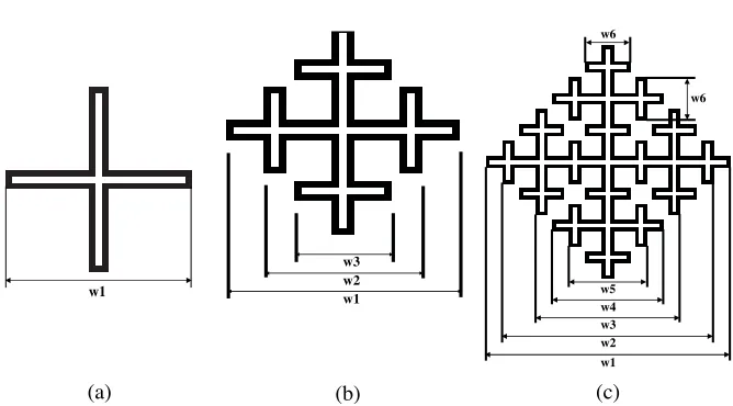
The fractal four legged elements of different orders are shown in Fig. 1. The black part means the aperture area. In order to make the elements more compact, as shown in Fig. 2, the array is aligned in a isosceles triangle way. It is noted that the isosceles triangle array can be seen as a rectangular array if two elements along y-axis are united as one element (see Fig. 2). Note that the elements are with eightfold symmetry. The FSS elements are all etched on a dielectric substrate, and Rogers RT5880 with thickness 1.27 mm is used as the substrate. The widths of the aperture line and the line enclosed by aperture line, denoted as w, are all the same for each element. The parameters of the FSS elements are given in Table 1. All dimensions are in millimeter. As that in [9], the ratio √2λ1/p is used as a figure of merit, where λ1 is the first resonant wavelength. For all the three cases, λ1 is approximately equal to 150 mm. The coefficient √2 is due to the fact that two elements are included in a unit cell. In order to avoid grating lobes, for normal incidence, the cutoff wavelength is given as [5]
w1
(c) (b)
(a)
w3 w2
w1 w5
w4 w3 w2 w1
w6 w6
Figure 1. Fractal four legged elements of different orders: (a) first order, (b) second order, (c) third order.
p 2
p
x
y
45
Figure 2. Schematic of array alignment and the symmetry property of elements.
While for 45◦ incidence, the cutoff wavelength is given as
λc =p/√2∗(1 + sin(45◦)). (5)
Therefore, the cutoff frequencies for the three cases are 5.47 GHz, 8.83 GHz, and 12.14 GHz, respectively.
1 2 3 4 5 -70
-60 -50 -40 -30 -20 -10 0
Frequency (GHz)
Transmission coefficient (dB)
calculated-normal calculated-45o TE calculated-45o TM simulated-normal
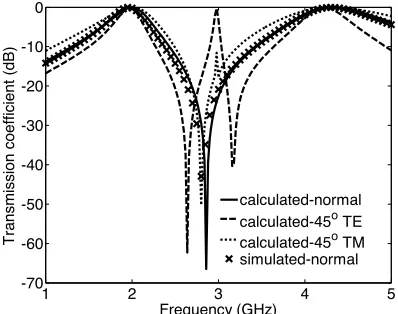
Figure 3. Transmission coefficient of the FSS with fractal first order four legged elements.
angles and polarizations. The ratio√2λ1/pis
√
2λ1/p=√2∗150/45.44 = 4.67 (6)
A second resonance is found at 4.34 GHz, 4.22 GHz, 4.32 GHz for normal incidence, 45◦ TE, and 45◦ TM, respectively. The shift of this resonant frequency is 0.12 GHz.
Figure 4 shows the transmission coefficient of the FSS with the second order fractal four legged elements. The first resonance is also stable for different incident angles and polarizations. The ratio√2λ1/p
is √
2λ1/p= √
2∗150/28.16 = 7.53 (7) A second resonance is found at 4.62 GHz, 4.58 GHz, 4.60 GHz for normal incidence, 45◦ TE, and 45◦ TM, respectively. The shift of this resonant frequency is 0.04 GHz, much less than that of the first case.
Table 1. Parameters of the FSS elements.
order p w w1 w2 w3 w4 w5 w6 1 45.44 0.71 41.89
2 28.16 0.44 25.96 15.40 11.88
1 2 3 4 5 6 7 8 -60
-50 -40 -30 -20 -10 0
Frequency (GHz)
Transmission coefficient (dB
)
normal 45o TE 45o TM
Figure 4. Transmission coefficient of the FSS with second order fractal four legged elements.
2 4 6 8 10 12
-70 -60 -50 -40 -30 -20 -10 0
Frequency (GHz)
Transmission coefficient (dB
)
normal 45o TE 45o TM
Figure 5. Transmission coefficient of the FSS with third order fractal four legged elements.
Figure 5 shows the transmission coefficient of the FSS with the third order fractal four legged elements. Again, the first resonance is stable for different incident angles and polarizations. The ratio√2λ1/p
is √
normal incidence, 45◦ TE, and 45◦ TM, respectively. The shift of this resonant frequency is 0.06 GHz. Though there are two other resonances at 8.00 GHz and 9.56 GHz, they are not stable for different incident angles and polarizations.
5. CONCLUSIONS
FSSs with fractal four legged aperture elements of different orders are discussed. The results show that by using higher order fractal elements, small periodicity and multiband FSSs can be obtained. For the third order, the ratio √2λ1/p reaches 10.36; four passbands for
normal incidence are obtained, however, only the first two bands are stable for different incident angles and polarizations. Larger ratio and more bands for normal incidence are expected by using higher order fractal elements. In practice, the line width can not be infinite thin, but larger than a certain value due to the technologic reasons. This in turn restricts the fractal orders. It should be noted that the band ratio λ2/λ1 can be tuned by changing the ratio w4/w1. The result is
in a good agreement with that by Ansoft HFSS. REFERENCES
1. Chakravarty, S., R. Mittra, and N. R. Williams, “Application of a microgenetic algorithm (MGA) to the design of broad-band microwave absorbers using multiple frequency selective surface screens buried in dielectrics,” IEEE Transactions on Antennas and Propagation, Vol. 50, No. 3, 284–296, 2002.
2. Wu, T. K. (ed.), Frequency Selective Surface and Grid Array, Wiley-Interscience, New York, 1995.
3. Wu, T.-K., “Four-band frequency selective surface with double-square-loop patch elements,”IEEE Transactions on Antennas and Propagation, Vol. 42, No. 12, 1659–1663, 1994.
4. Guo, C., H. Sun, and X. Lu, “A novel dualband frequency selective surface with periodic cell perturbation,” Progress In Electromagnetics Research B, Vol. 9, 137–149, 2008.
5. Romeu, J. and Y. Rahmat-Samii, “Fractal FSS: A novel dual-band frequency selective surface,”IEEE Transactions on Antennas and Propagation, Vol. 48, No. 7, 1097–1105, 2000.
7. Barlevy, A. S. and Y. Rahmat-Samii, “On the electrical and numerical properties of high Q resonances in frequency selective surfaces,”Progress In Electromagnetics Research, PIER 22, 1–27, 1999.
8. Li, L., D. H. Werner, J. A. Bossard, and T. S. Mayer, “A model-based parameter estimation technique for wide-band interpolation of periodic moment method impedance matrices with application to genetic algorithm optimization of frequency selective surfaces,”
IEEE Transactions on Antennas and Propagation, Vol. 54, No. 3, 908–924, 2006.
9. Parker, E. A. and A. N. A. El Sheikh, “Convoluted array elements and reduced size unit cells for frequency-selective surfaces,” IEE Proceedings-H, Vol. 138, No. 1, 19–22, 1991.
10. Barbagallo, S., A. Monorchio, and G. Manara, “Small periodicity FSS screens with enhanced bandwidth performance,” Electronics Letters, Vol. 42, No. 7, 382–384, 2006.
11. Azaro, R., G. Boato, M. Donelli, A. Massa, and E. Zeni, “Design of a prefractal monopolar antenna for 3.4–3.6 GHz Wi-Max band portable devices,” IEEE antennas and wireless propagation letters, Vol. 5, 116–119, 2006.
12. Azari, A., “Ultra wideband fractal microstrip antenna design,”
Progress In Electromagnetics Research C, Vol. 2, 7–12, 2008 13. Salmasi, M. P., “A novel broadband fractal Sierpinski shaped,
microstrip antenna,” Progress In Electromagnetics Research C, Vol. 4, 179–190, 2008.
14. Werner, D. H. and D. Lee, “A design approach for dual-polarized multiband frequency selective surfaces using fractal elements,”