Doctoral Dissertations University of Connecticut Graduate School
8-30-2018
Performance Evaluation of Shear Connectors
Embedded in Ultra-High Performance Concrete as
Part of a Bridge Repair Method
Dominic Kruszewski
University of Connecticut - Storrs, [email protected]
Follow this and additional works at:https://opencommons.uconn.edu/dissertations
Recommended Citation
Kruszewski, Dominic, "Performance Evaluation of Shear Connectors Embedded in Ultra-High Performance Concrete as Part of a Bridge Repair Method" (2018).Doctoral Dissertations. 1963.
Dominic Kruszewski, PhD
University of Connecticut, 2018
Corrosion is one of the most dominant forms of deterioration in steel bridge girders. U.S. federal and state agencies spend billions of dollars annually on bridge rehabilitation as a direct result of corrosion. Even with these efforts, approximately $125 billion is needed to address the current backlog of structures in need of repair. Over time, corrosion leads to section loss of critical load bearing components, hindering the structural integrity of the bridge. To strengthen weakened girders ends with section loss, a structurally efficient repair option has been developed. In this repair, headed shear studs are welded to the intact portion of the web plate just above the bearing. The studs are encased in a panel of Ultra-High Performance Concrete (UHPC), which is cast to the bottom flange. This creates an alternate load path to omit the weakened web plate, transferring the forces through the studs and into the UHPC panels.
However, the success of the proposed repair hinges on the interaction between the headed studs and UHPC cast and therefore must be thoroughly assessed. In this study, a five-phase approach is deployed to better understand the critical load-transfer mechanism as part of this repair. First, an extensive series of push-out tests was conducted to evaluate the mechanical behavior of the headed studs when welded on thin web plates and embedded in UHPC. Next, design considerations such as eccentric loading, cover for studs, concrete embedment variations, concrete curing conditions, and welding are evaluated to aid engineers during field implementation. The third phase consisted of a high-fidelity finite element analysis to validate the experimental results. Further design parameters such as eccentric loading and stud-diameter-to-web-thickness ratios for various limit states were evaluated. In the fourth phase, a corrosion investigation was conducted to assess the durability of the headed studs when embedded in UHPC. Finally, alternate shear connectors such as threaded rods and UHPC dowels are evaluated experimentally to provide flexibility to the designer as an alternative option to headed studs. The results of this work are used to facilitate the field implementation of the proposed repair method by addressing critical design parameters.
i
Performance Evaluation of Shear Connectors Embedded in Ultra-High Performance Concrete as Part of a Novel Bridge Repair Method
Dominic Kruszewski
B.A., University of Connecticut, 2014
M.S., University of Connecticut, 2016
A Dissertation
Submitted in Partial Fulfillment of the
Requirements for the Degree of
Doctor of Philosophy
at the
University of Connecticut
ii
Dominic Kruszewski
iii
APPROVAL PAGE
Doctor of Philosophy Dissertation
Performance Evaluation of Shear Connectors Embedded in Ultra-High Performance Concrete as Part of a Novel Bridge Repair Method
Presented by Dominic Kruszewski, B.S., M.S. Major Advisor ___________________________________________________________________ Arash E. Zaghi Major Advisor ___________________________________________________________________ Kay Wille Associate Advisor ___________________________________________________________________ Jeongho Kim Associate Advisor ___________________________________________________________________ Wei Zhang University of Connecticut 2018
iv
First, I would like to thank my advisors, Dr. Arash E. Zaghi and Dr. Kay Wille, for their
guidance and unwavering support throughout my studies. Their advising reached me on more than
just an academic level. They helped shape the man I am today through many insightful
conversations about my work, my life, and even broader topics. I owe a lot to my advisors for
encouraging my transformation throughout these past few years.
I would also like to thank my advisory committee members, Dr. Jeongho Kim and Dr. Wei
Zhang, for their guidance and advice throughout my work. Their unique insight and exceptional
ability to convey engineering concepts allowed me to bolster the quality of my work.
Next, I would like to thank all of my friends and colleagues who have made this journey
possible. From my officemates, to the graduate students working in this lab, to the specialists in
the machine shop and the front office of the department. Being a graduate student may seem like
a solo adventure, but success is driven and created through the teamwork of many people from all
areas.
Finally, I would like to thank my family for making this possible. This includes my mother,
Alex, my father, Alex, my brother, Kasper, and even my dogs, Rex, Cici, and Lola, and my cat
Kobe. My family has been my rock during these past few years and they have always encouraged
me to work hard and follow my dreams, no matter how hard the path may seem. I would like to
thank my beautiful girlfriend, Lauren, who inspired me to work harder and provided incredible
patience and support throughout the hardest of times. I could not have done it without you all.
v
Ch. 1: Push-Out Behavior of Headed Shear Studs Welded on Thin Plates 3
Ch. 2: Design Considerations for Headed Studs Embedded in UHPC 40
Ch. 3: Finite Element Validation of Headed Studs Embedded in UHPC 84
Ch. 4: Durability Evaluation of Headed Studs Embedded in UHPC 126
Ch. 5: Experimental Evaluation of Shear Connectors Embedded in UHPC 151
Ch. 6: Sample Design of Various Shear Connectors 175
Appendix A: Raw Experimental Data 201
1 Chapter 1
Push-Out Behavior of Headed Shear Studs Welded on Thin Plates and Embedded in UHPC
2 INTRODUCTION
Deterioration of steel bridge girders is a pressing issue facing today’s infrastructure. The 2017 ASCE Infrastructure Report Card indicates that approximately 15% of the 56,000 structurally
deficient bridges in the United States suffer from corrosion damage [1]. Corrosion damage is
particularly significant in bridges with expansion joints at the piers or abutments (Fig. 1). Faulty
expansion joints permit water and deicing chemicals to leak through to the superstructure which
induces corrosion at the girder end [2]. A significant reduction in bearing capacity may occur if
corrosion reduces the thickness of the web plate near the bearing region [3, 4]. The current repair
procedure to remedy girders with section loss is costly, time-consuming and labor intensive. The
method involves jacking the superstructure, removing the corroded section of steel, welding in
new steel, and lowering the superstructure back into place [5].
Fig. 1. Corrosion at Girder End
A novel repair method for deteriorated bridge girders has been proposed to improve the current
procedure [6]. The proposed method involves welding headed shear studs to the intact portion of
the web outside of the corrosion damaged portion with reduced area. A panel of ultra-high
3
the welded shear studs. The UHPC cast creates a force-transfer path to enhance the bearing
capacity of the weakened end. A schematic of the proposed repair is shown in Fig. 2. The procedure
does not require jacking of the superstructure, which significantly reduces the cost of the repair.
As the studs are welded to localized portions of the girder, minimal cleaning of the surface is
required.
a) Corrosion at Girder Ends b) Studs Welded to Intact Web c) Cast UHPC Panel
Fig. 2. Concept of Proposed UHPC Repair
The headed shear studs play a critical role in transferring the bearing forces from the web
to the UHPC panel. Therefore, this study focuses on investigating their performance as part of the
proposed repair. First, the studs’ capacity welded onto thin plates is validated since the webs of bridge girders are typically thinner than 10 mm. Second, because the arrangement of the studs may
vary based on the available surface area on the web plate, the effect of tight spacing and staggered
position is assessed. Lastly, the weldability of the new studs to an older steel material with different
metallurgical properties must be examined. To investigate these parameters, push-out experiments
were conducted with headed shear studs embedded in UHPC and welded to 9.5-mm thick web
plates that were salvaged from the old Pearl Harbor Memorial Bridge (Connecticut, U.S.A.) which
was constructed in 1958. Three stud diameters, several stud layouts, and different compressive Corrosion Headed studs
4
strengths of UHPC were evaluated. A total of 13 push-out experiments were conducted to evaluate
these parameters. A unique loading protocol was adopted to reduce the demand on the thin web
plate. The force was applied onto the flanges of the section, through the web, and finally to the
studs which were embedded in UHPC. The experimental capacities generated from the tests were
compared to those proposed by other researchers. It was shown that headed studs welded to a thin
web plate achieve full capacity without imposing damage to the base web plate or UHPC panels.
Based on the tests, an existing stud capacity formulation was refined for predicting the shear
strength of headed studs embedded in UHPC.
PERFORMANCE OF HEADED STUDS IN UHPC
The behavior of headed studs embedded in conventional concrete has been widely studied
and is well known. When studs are embedded in regular-strength concrete with a compressive
strength of 20 MPa, the failure mode is governed by conical failure of the surrounding concrete
with partial yielding of the stud [7]. When headed studs are embedded in ultra-high performance
concrete (UHPC) and loaded in shear, their mechanical behavior differs from when they are
embedded in conventional concrete. Push-out experiments have been conducted to compare the
performance of headed studs embedded in regular- and high-strength concrete, and UHPC [8]. It
was concluded that studs embedded in regular-strength concrete exhibit higher ductility than when
embedded in a high-strength one and UHPC. Another study found that the shear capacities
generated by 16- and 22-mm diameter studs embedded in UHPC were consistently higher than
those outlined by AASHTO and Eurocode-4 [9]. It has also been observed that headed studs with
5
diameter [10]. Even with a cover less than 25 mm, the failure mode of headed studs embedded in
UHPC is still governed by stud shank failure [11]. Fatigue performance of headed studs in UHPC
was also evaluated; it was found that when studs are embedded in UHPC, their expected fatigue
life is longer than those embedded in regular strength concrete (RSC). Experimental evaluation of
demountable headed stud shear connectors in UHPC was conducted [13]. It was found that a stud
aspect ratio less than 1.5 resulted in UHPC breakout; for larger aspect ratios, stud fracture was the
governing failure mode. These studies all generate a common observation that the failure
mechanism of studs embedded in UHPC is typically stud shank failure with little or no damage to
the UHPC.
Another unique advantage of studs embedded in UHPC involves the presence of a weld
collar which provides an increase in shear capacity when loaded in shear [14]. The weld collar is
formed at the base of the stud during the welding process (Fig. 3). Its diameter is slightly larger
than the stud shank because of the shape of the ferrule that contains the molten pool of metal during
welding.
Fig. 3. Typical Headed Stud After Welding Process Weld Collar
Stud Shank Stud Head
6
This observation is particularly prevalent in studs embedded in concrete with a higher
compressive strength. If the concrete is strong enough to resist micro-cracking at the weld collar
interface, the weld collar will bear onto an area with a slightly larger diameter. To account for the
bearing contribution of the weld collar, a formula for predicting the shear strength of headed studs
embedded in high-strength concrete (f’c > 90 MPa) was derived as the following:
𝑃𝑢 = 𝐴𝑠𝑐𝑓𝑠𝑢 + 𝜂𝑓𝑐𝑢𝑑𝑤𝑐𝑙𝑤𝑐 (1)
, where Asc is the area of the stud shank, fsu is the ultimate tensile capacity of the stud, fcu is the
compressive strength of the concrete, dwc is the diameter of the weld collar, lwc is the height of the
weld collar, and η is an empirical factor typically taken as 2.5 for UHPC.
Although formulations have been proposed for headed studs embedded in UHPC by
several researchers [12, 14], these equations are based on tests conducted with studs welded to the
flange of a new steel shape. The flange thickness in these experiments was at least 12 mm. When
considering the proposed repair, it is important to validate the studs’ capacity when welded to plates thinner than 12 mm. Furthermore, it is important to understand the mechanical and
metallurgical properties of an old substrate material since the proposed repair targets older bridges.
US specifications for structural steel in 1958 called for Type A373-58T steel with a minimum
yield strength and ultimate strength of 220 MPa and 400 MPa, respectively [15]. These mechanical
properties differ from the material specified for modern construction, such as Type A992 with a
minimum yield and tensile strength of 345 MPa and 450 MPa, respectively [16]. In addition, the
weldability of new studs to an older material with different metallurgical properties must be
7 FABRICATION OF PUSH-OUT SAMPLES
A total of 13 push-out samples were fabricated to confirm the feasibility of the proposed
repair method and quantify individual stud shear capacity. To obtain results relevant to the repair,
rolled steel girders were salvaged from an old bridge which was erected in 1958. The base steel
section was fabricated by cutting the salvaged girders into approximately 300-mm long sections.
The headed shear studs were welded to the web of the section using a stud gun to adhere to common
construction practices (Fig. 4a, b). Steel forms were pressed against the web of the section so that
UHPC panels could be cast (Fig. 4c, d). The symbol HS defines the height of the stud as outlined
in Table 1. Foam sheeting was used to separate the UHPC panels under the web. This allowed the
panels to behave separately during the experiment without the web bearing onto the UHPC. The
final geometry and layout of the push-out specimens is illustrated in Fig. 5.
a) Welding of Studs Using Stud Gun b) Beam With Studs Welded
c) Forms Pressed Against Web for Casting d) Completed Push-Out Specimen Fig. 4. Fabrication of Push-Out Specimens
8
a) Plan b) Elevation c) Cross Section Fig. 5. Geometry of Completed Push-Out Specimen
The parameters studied include a) stud diameter, b) stud layout, c) stud spacing, and d) UHPC
compressive strength. These were selected to address the potential design options that may be
considered for field installation. For example, a tightly spaced, staggered pattern may be favorable
when a limited surface area is available for welding. Larger diameter studs may also be an option
when a higher capacity is needed. Further, it is important to understand the influence of the UHPC
compressive strength if it does not develop in the field as expected.
Fig. 6 shows the layouts of the stud arrangements. The symbols SV and SH represent vertical
spacing and horizontal spacing respectively from the center of the studs. Pattern A is a single
column of four studs on each side (eight in total) spaced at four times the diameter of the stud
(4db); Pattern B is similar to the benchmark but with a vertical stagger between the two sides;
Pattern C contains a vertical and horizontal stagger with vertical and horizontal spacing of 2db;
Pattern D is a single column of two studs with larger diameters (16 mm and 19 mm) welded
9
two columns and spaced at 4db. All spacing is considered center-to-center from the stud shank.
The dimensions of the UHPC panels were kept constant in all specimens.
Fig. 6. Stud Patterns
Table 1 summarizes the tests conducted in this study. The specimen identification format is as
follows: D (diameter of stud shank) (stud batch series) S (number of studs) – (stud pattern) (sample
identification number). Three different stud shank diameters of 12, 16, and 19 mm were examined.
The batch series letter (“a” or “b”) refers to the batch of headed shear studs used as outlined in the Material Properties section. Five batches with varying mechanical properties were used for the
experimental specimens (two for 12 mm studs, one for 16 mm, and two for 19 mm). The stud
pattern refers to the layout of the studs as shown in Fig. 6. For example, sample D12aS8-A2
contains eight headed studs with a 12 mm diameter from batch “a”. The studs are welded according
10
Table 1. Summary of Experiments
Specimen ID f'c (MPa) Stud Diam. (mm) HS SV SH D12aS8-A1 131 12 4db 4db -- D12aS8-A2 114 12 4db 3db -- D12bS8-A3 145 12 4db 4db -- D12aS8-A4 193 12 4db 4db -- D12aS4-A5 158 12 4db 4db -- D12bS8-A6 165 12 4db 4db -- D12bS8-A7 180 12 4db 4db -- D12aS8-B1 145 12 4db 4db -- D12aS8-C1 117 12 4db 2db 2db D16aS4-D1 110 16 4db 4db -- D19aS4-D2 141 19 2.7db 4db -- D19aS4-D3 141 19 4db 4db -- D12aS8-E1 134 12 4db 4db 4db EXPERIMENTAL METHODOLOGY
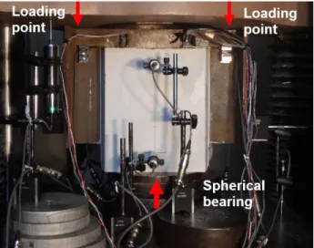
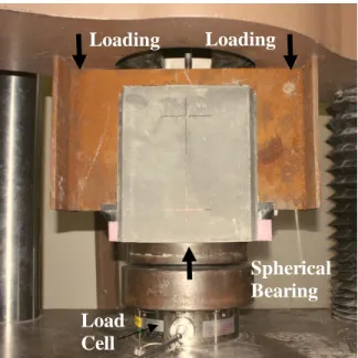
All samples were tested using a 1800-kN hydraulic load frame. Each push-out specimen
was mounted such that the UHPC panels were resting on a 250-mm diameter spherical bearing to
account for small rotations due to imperfections in the sample. To prevent local buckling of the
web, the loading was applied onto the beam through the flanges (Fig. 7). This was accomplished
by utilizing a hole in the top platen intended for fixtures, which omitted the web of the section.
The forces were transferred from the flanges to the web, and finally to the studs which were
11
similar to how they would be loaded when applied to a bridge. The bottom of the UHPC panels
were not fixed which allowed for lateral spreading throughout the test.
Fig. 7. Instrumented Specimen for Push-Out Experiments
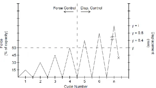
The push-out experiments were conducted using a cyclic loading protocol. A schematic of
the loading protocol is shown in Fig. 8.The four initial load steps were conducted using force
control at a loading rate of 2.2 kN/s. Each sample was loaded to 15%, 30%, 45% and 60% of its
theoretical capacity as outlined by AASHTO [17]. After each step, the specimen was unloaded
back to 4.5 kN. After the first four cycles, the sample was loaded with increments of 0.4 mm per
cycle using displacement control at a loading rate of 0.004 mm/s until failure.
12
Fig. 8. Loading Protocol for Push-Out Experiments
INSTRUMENTATION
Several different sensors were used to measure slippage, strains on the web, strain in studs,
and global deformations. Uniaxial strain gauges were embedded inside the stud shanks to capture
axial strains. A hole with a diameter of 2 mm was drilled at the center to approximately 80% of
the length of the stud from its head. A high-strength epoxy was injected into the hole until it was
filled and free of air voids. The specialized uniaxial strain gauges were embedded into the
epoxy-filled hole such that the tip of the gauge remained 2 mm away from the bottom of the drilled hole
(Fig. 9a). Biaxial strain gauges were installed onto the web plate above the weld collar (Fig. 9b).
These were installed to observe the strain values on the compressed portion of the web plate and
13
a) Stud Gauges b) Biaxial Strain Gauges Attached at the Base of the Studs Fig. 9. Uniaxial and Biaxial Strain Gauges for Load Transfer Behavior
Four cantilever-type slip displacement transducers were attached to the web plate using
high-strength magnets. These sensors extended onto the UHPC panels to record the relative
displacement, i.e. slip, between the web and the UHPC. Based on this displacement, stiffness and
ductility of the system may be determined. Seven displacement transducers were used to observe
global displacements throughout testing. Two sensors were installed on the left and right flanges
of the beam to capture the movement of the steel section. These sensors were used to monitor any
possible rotations. Two displacement transducers were installed on each UHPC panel to capture
out-of-plane movements. Each sensor was placed along the centerline approximately 65 mm from
the top and bottom of the UHPC panel. Finally, a displacement sensor was placed at the top platen
to monitor the machine displacement. An overview of the global instrumentation is shown in Fig.
10.
14
Fig. 10. Overview of Global Instrumentation
MATERIAL PROPERTIES
UHPC is defined as a cementitious composite material made of optimized granular
constituents and a water to cementitious materials ratio less than 0.25 [18]. The commercially
available UHPC, Ductal JS1212 by Lafarge-Holcim, was used for all experiments. This mix design
was selected due to its high early-age strength gain. It is specified to achieve a compressive
strength of 83-MPa in 12 hours at 49°C curing. This feature is particularly advantageous to the
proposed repair because it enables the opening of a bridge in a short time after casting. The UHPC
mix is composed of a premix powder containing a mixture of cement, silica fume, ground quartz,
and sand, three admixtures, and high-strength steel fibers. The admixtures include two types of Lateral Disp. Sensors Slip Sensors Global Disp. Flange Disp. Flange Disp.
15
high range water reducers (HRWR) as well as a non-chloride based accelerator. The steel fibers
are 0.2 mm in diameter and 12 mm long with a minimum specified tensile strength of 2,000 MPa.
The fiber content is 2% by volume. The composition by weight is shown in Table 2.
Table 2. Composition of the UHPC Mix
Component % by weight Premix 86.6 Water 5.1 HRWR 1 0.7 HRWR 2 0.5 Accelerator 0.9 Steel Fibers 6.2
Fig. 11a shows a spread test which was conducted as a quality control measure of the
workability of the UHPC. A typical spread for this mix is 250 mm. The mix was accepted if the
spread of each UHPC mix was 250±12 mm. Twelve cylinders (75 x 150 mm) were cast from each
mix for compressive strength testing. These cylinders were tested at 12 hrs, 24 hrs, and 3, 7, 14,
16
(a) Spread Test of UHPC (b) Strength Gain Over Time Fig. 11. Quality Control for Ductal JS1212
To evaluate the mechanical properties of the steel beam sections, 6 coupons were fabricated in
accordance with ASTM E8 [19]. For the studs, due to their size and geometry, custom coupons
were fabricated by removing the head of the stud and machining the stud shank into a flat coupon.
The middle of the shank was further machined to produce a circular throat with a diameter of
7 mm. The throat length was 3 times longer than the throat diameter to reduce triaxiality effects.
Five various stud batches were used in this experimental program. Two batches were used for
studs with a 12-mm diameter, one batch for studs with a 16-mm diameter, and two batches for
studs with a 19-mm diameter. All the steel samples were tested in uniaxial tension in accordance
with ASTM E8 until rupture (Fig. 12). Table 3 shows a summary yield and ultimate stress values.
Time (days) U H PC f'c (M Pa) 0.5 1 2 3 4 5 7 10 20 30 50 100 0 30 60 90 120 150 180
17
Fig. 12. Ruptured Stud Coupons
Table 3. Summary of Mechanical Properties of Steel Material
Steel Series Yield Stress, Fy (MPa) Ultimate Stress, Fu (MPa) Beam Section 286.1 448.2 D12a 404.0 484.0 D12b 426.1 545.4 D16a 387.5 502.6 D19a 419.9 489.5 D19b 422.6 503.0
RESULTS AND DISCUSSION
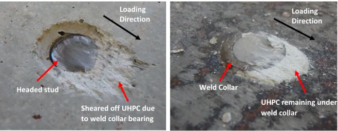
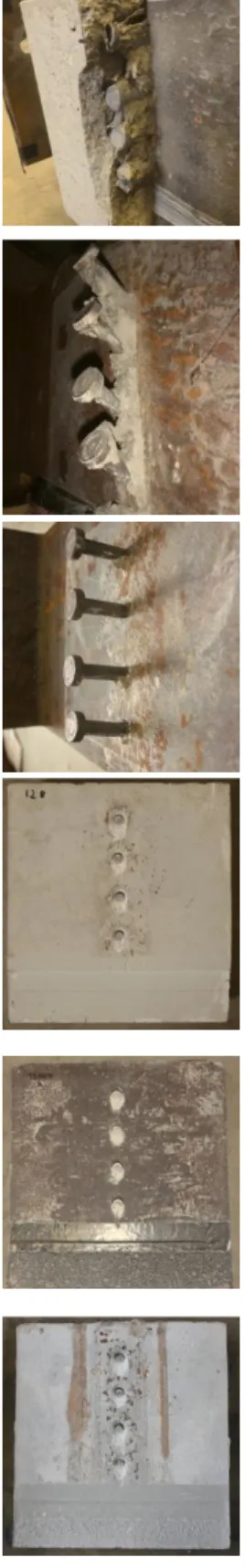
The failure mode for all specimens was governed by shear rupture of the stud shank at the
interface of the weld collar and stud shank. The weld collar remained almost intact on the web
plate and the entire stud remained embedded in the UHPC panel (Fig. 13). A thin wedge of the
UHPC sheared off due to bearing action of the weld collar. All the stud patterns failed in a similar
18
(a) Stud Embedded in UHPC After
Failure
(b) Weld collar remaining on web plate
Fig. 13. Typical Shear Failure Mode of Headed Studs Embedded in UHPC Weld Collar
Headed stud
Sheared off UHPC due to weld collar bearing
UHPC remaining under weld collar
Loading
19
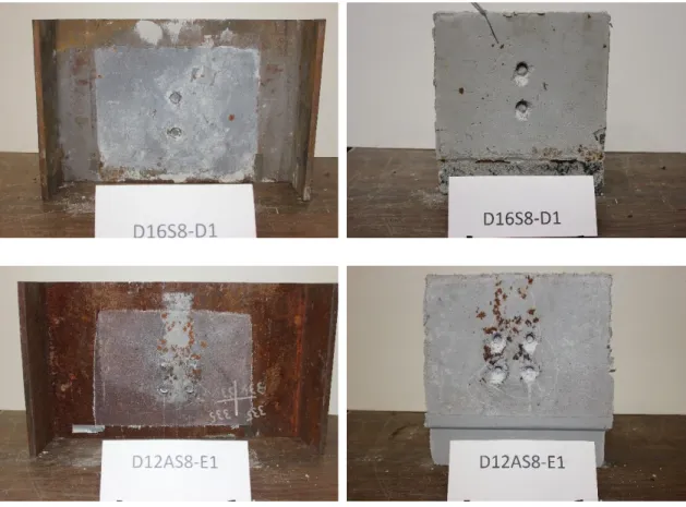
Stud Patter n
Base Steel Section UHPC Panel
A
B
20
D
E
Fig. 14. Summary of Failed Samples for All Stud Arrangements
Values of elastic shear stiffness (ke), yield slip (𝛿𝑦), maximum slip (𝛿𝑢), yield force (𝑃𝑦), experimental capacity (Pu), and the weld collar bearing force (Pwc) at experimental capacity were
recorded for all specimens. Elastic shear stiffness (ke) was calculated using the slope of the force
vs. slip curve up to one-third of the overall load bearing capacity [20]. The slip is defined as the
relative displacement between the UHPC panel and the web plate. The maximum and residual slip
at loading cycle i is denoted by 𝛿𝑖,𝑚𝑎𝑥 and 𝛿𝑖,𝑟𝑒𝑠, respectively. Four slip sensors were used to monitor the relative displacement between the steel beam and the UHPC panel. The average value
is presented for all data herein. Figure 15 shows a typical force-slip relationship. The yield slip
and yield force were generated by a 0.1 mm offset from the origin shown by the blue offset line as
21
16- and 19 mm studs to capture the yield point for various stud diameters with different ultimate
capacities. The slopes varied according to the elastic stiffness of each respective diameter. The
force per stud was calculated as the total bearing force resisted by the specimen divided by the
number of studs. The bearing contribution of the weld collar (Pwc) was calculated by subtracting
the contribution of the stud shank (AscFu) from the total experimental capacity of the stud. Table 4
shows a summary of the test results.
Fig. 15. Parameters for Typical Force vs. Slip Curve
𝜹𝒖 𝜹𝒚 ke Yield Force, Py Ultimate Force, Pu 𝜹𝒊,𝒎𝒂𝒙 𝜹𝒊,𝒓𝒆𝒔
22
Table 4. Summary of Experimental Results
Specimen
ID f'c ke
𝜹𝒚 𝜹𝒖 Py Pu PWC PWC/Pu
Unit MPa kN/mm mm mm kN kN/stud kN/stud % D12aS8-A1 131 181.5 0.330 4.65 41.5 66.7 8.43 8.15 D12aS8-A2 114 167.4 0.380 5.86 40.3 62.3 1.54 1.59 D12bS8-A3 145 228.5 0.241 4.47 52.5 69.8 5.41 5.00 D12aS8-A4 193 273.2 0.193 3.25 51.4 70.7 14.64 13.35 D12aS4-A5 159 200.2 0.305 5.91 51.6 66.7 8.43 8.15 D12bS8-A6 179 260.4 0.229 3.43 53.1 73.8 7.42 6.49 D12bS8-A7 166 240.7 0.231 3.46 50.3 70.5 6.38 5.84 D12aS8-B1 145 297.2 0.264 5.15 52.1 68.5 3.34 3.15 D12aS8-C1 117 201.3 0.293 4.71 47.9 62.3 1.54 1.59 D16S4-D1 110 363.9 0.344 4.42 84.7 101.4 3.07 1.96 D19aS4-D2 141 391.4 0.312 6.78 105.0 144.6 7.92 3.54 D19aS4-D3 141 405.9 0.267 4.84 107.6 150.3 10.80 4.63 D12aS8-E1 134 150.7 0.351 5.08 51.6 65.4 6.36 6.28
Fig. 16a shows the backbone force vs. slip curves for all samples. Slip is an important
parameter for shear connections because it reveals the stiffness and ductility of the system. The
12-, 16- and 19-mm diameter studs generated an average capacity of 68.2, 101.4 and 147.7
kN/stud, respectively. The studs exhibit ductile behavior as they sustain the loading over an
average slip of 4.60, 4.42 and 5.81 mm for the 12-, 16-, and 19-mm studs, respectively. However,
these slip capacities do not satisfy the ductility requirements of 6 mm as outlined in Eurocode-4
[21]. On average, the weld collar attributed for 5.4% of the shear resistance for all samples.
23
strengths. For example, when the UHPC compressive strength was 114 MPa, the weld collar was
only responsible for 1.6% of the stud capacity. However, for a compressive strength of 193 MPa,
the weld collar attributed for 13.3% of the capacity. This is further shown in Fig. 16b which shows
the normalized shear strength of a single stud as a function of compressive strength of UHPC. The
graph is normalized because of the various diameters and material strengths of the studs. It is
shown that as the compressive strength of the UHPC increases, the shear strength of the headed
stud also increases. When the UHPC compressive strength increases from 114 to 193 MPa, the
shear strength increases by approximately 14%. This may be due to less micro-cracking at the
interface between the weld collar and the UHPC. At higher compressive strengths, the intact
UHPC provides more resistance to the bearing action of the weld collar. This effect may also be
pronounced further for larger weld collars with more available surface area. This means that the
overall shear resistance of the stud is dependent on the UHPC which engages the weld collar more
effectively at higher compressive strengths.
a) Force vs. Slip Summary b) Strength of Stud vs. UHPC f’c Fig. 16. Ultimate Strength of Headed Studs
Slip (mm) F or ce (kN /st u d ) 0 1 2 3 4 5 6 0 50 100 150 200 12 mm 16 mm 19 mm
24
To further understand the influence of the UHPC compressive strength, the slip at the yield
point was studied (Fig. 17). The trend line suggests that the slip at yield decreases as the UHPC
compressive strength increases. When the UHPC compressive strength increased from 114 MPa
to 193 MPa, the yield slip decreases from 0.380 mm to 0.193 mm, respectively. This may be due
to less localized cracking near the weld collar, which results in a more efficient shear connection
between the stud and the UHPC. A higher strength UHPC may resist micro-cracking in the elastic
range which allows the material to contain the studs more effectively. This behavior reduces
flexure of the stud and promotes shear deformation, resulting in a stiffer system.
Fig. 17. Slip at Yield Point vs. UHPC Compressive Strength
Fig. 18 illustrates the relationship between residual slip and maximum slip experienced by
the system during loading and unloading cycles. This graph provides information regarding the
systems’ ability to recover from the induced displacement. Maximum slip is defined as the slip experienced by the system at each cycle i. Residual slip is defined as the slip of the system when
25
the sample has been unloaded from cycle i. Typically, residual displacement can be considered
plastic displacement. In this graph, a slope approaching 0 represents an elastic system (i.e. no
residual displacement). If the slope of the curve approaches 1, it indicates that the system has
experienced plastic deformation. The figure shows that the system is in the elastic range when
maximum slip is less than ~0.3 mm. After this point, the slope of the curve increases to
approximately 0.89 mm/mm, suggesting more damage accumulation between the studs and the
UHPC. From here, damage accumulation is constant as characterized by the linear shape of the
curve.
Fig. 18. Residual Slip vs. Maximum Slip
Damage initiation is an important parameter when studying the load-transfer behavior
between the headed studs and the UHPC. Understanding the source and progression of damage
can provide information to further optimize the shear connection. Damage was captured by
comparing the stiffness at each loading cycle (ki) against the elastic stiffness (ke). The stiffness at Maximum Slip (mm) Res idu al Sl ip (m m ) 0 1 2 3 4 5 6 0 1 2 3 4 5 6 12 mm 16 mm 19 mm
26
each cyclic loading (ki) is defined using the change in slope between the residual slip and
maximum slip at each cycle. A damage variable of 0 indicates that the connection behaves
elastically since the system experiences no residual displacement. A damage variable of 1 indicates
that the connection has no stiffness remaining and is thus fully damaged or ruptured. The damage
variable, Di, is calculated using the following expression:
𝐷𝑖 = 1 − 𝑘𝑖
𝑘𝑒 (2)
Fig. 19 illustrates the damage initiation and reduction in stiffness of a single stud. In
general, over 50% damage was experienced by all samples before a slip of 1 mm. This may be due
to a combination of micro-cracking of the UHPC and yielding of the studs. At larger slip ranges
(i.e. more than 1 mm), the damage curve flattens, indicating less damage accumulation when the
studs begin to undergo shear deformation. This is because the change in stiffness is minimal in the
plastic region due to strain hardening of the stud material. The minimum and maximum damage
variable prior to rupture is 0.61 (sample D19S4-D2) and 0.96 (sample D12S8-A3), respectively.
Several factors may contribute to the variation in damage: a) higher UHPC strengths generate more
resistance to micro-cracking and thus less damage, b) less UHPC cover provides smaller resistance
to tensile splitting and thus more damage, and c) poor quality weld collars may lead to more
residual slip as the efficiency of the connection is debilitated. Sample D12S8-A3 showed the
highest damage because of the reduced spacing between studs (3db). The reduced spacing may
have caused overlapping of the bearing regions of the studs inducing higher compressive demands
on the UHPC. No clear trend was observed in damage initiation when comparing the stud
27
Post-yield stiffness is defined as the stiffness of the stud at each cycle i after yielding is
observed. Stiffness measurements were calculated by recording the slope of the force-slip curve at
each loading cycle. This stiffness was divided by the number of studs to calculate the theoretical
stiffness of one stud. For studs with a diameter of 12, 16 and 19 mm, the stiffness per stud
decreased by 27.2, 28.8, and 19% respectively. The benchmark stud arrangement (A) generated a
consistently higher stiffness than samples with staggered stud arrangements (B, C, E). The studs
with larger diameters generated a higher stiffness due to their ability to carry higher forces over
the same slip range.
a) Damage Initiation b) Reduction in Stiffness After Yielding
Fig. 19. Damage Initiation and Stiffness Reduction
Since the headed studs are welded onto a thinner plate than traditionally used in push-out
tests, understanding the demands on the web plate is critical when considering the proposed repair.
If the web plate experiences excessive strain and/or yielding, the proposed repair may not be
Slip (mm) Dam ag e Pa ram ete r 0 1 2 3 4 5 6 0 0.2 0.4 0.6 0.8 1 12 mm 16 mm 19 mm Slip (mm) Stif fne ss Per Stu d ( kN/m m ) 0 1 2 3 4 5 6 7 0 100 200 300 400 12-mm 16-mm 19-mm D12S8-A3 D12S8-E1 D12S8-C1
28
favorable as additional damage to the structure must be avoided. Fig. 20 shows the strain transfer
between the stud and adjacent web plate onto which it was welded. In Fig. 20a, the loading and
unloading cycles are shown in dashed gray and the generated backbone curve is shown solid black.
Fig. 20b shows the backbone curves for all samples tested. The stud strains shown are axial, as
shear strain in the studs is difficult to capture during testing. When initial loads are applied to the
system, the web and studs act in unison to resist the demands in the elastic range. Once the studs
reached their yield strength, the web no longer experiences additional strain; instead, the demand
is fully transferred to the studs. The flattening of the strain curve at higher cycles indicates this
behavior. The studs continue to deform until they rupture in shear. Each sample tested in this series
showed comparable stud strains, indicating no significant shear lag effects. The average
detachment of the UHPC panel due to axial elongation of the studs is 1.01 mm.
a) Typical Strain Transfer with Cyclic Loading
b) Backbone of Strain Transfer for All Samples
Fig. 20. Transfer of Strain Between Web and Headed Shear Studs
Another important parameter of interest regarding the proposed repair is the effect of
various stud diameters. Welding larger studs may be favorable when a larger capacity is needed
and little surface area is available on the web plate. Fig. 21 illustrates the relationship between web
Axial Stud Strain ()
Vertical Web S train ( ) 0 2000 4000 6000 8000 10000 0 5000 10000 15000 20000 12-mm 16-mm 19-mm
29
strains generated adjacent to the stud as a function of stud diameter. The trend indicates that the
strain experienced by the web is larger as the stud diameter increases. On average, the studs with
a diameter of 12, 16 and 19 mm generated a strain of 6,950, 9,800 and 16,200 με respectively. The
12-mm studs generated a larger deviation in web strain due to a variety of stud layouts tested. For
example, a sample with vertical stagger (layout B) experienced larger vertical web strains,
approximately 13,000 με, than a sample with no stagger (layout A) which experienced
approximately 9400-με. However no significant deterioration in capacity was observed when
comparing the stud arrangements. These results indicate that headed studs up to a diameter of 19
mm can be welded on web plates with a thickness of 9.5 mm, validating the feasibility of the repair.
Fig. 21. Web Strain vs. Stud Diameter
CAPACITY OF HEADED STUDS IN UHPC
Equation (1) proposes that the capacity of a headed shear stud embedded in UHPC is the
sum of the shear resistance generated by the area of the stud shank (AscFu) and the bearing Stud Diameter (mm) Ve rti ca l W eb S tra in ( ) 10 12 14 16 18 20 0 4000 8000 12000 16000 20000
30
resistance generated between the weld collar and the UHPC panel (ηf’cdwclwc). The results
generated through this experimental program confirm that the weld collar plays a significant role
in the shear capacity of a headed stud. However, the weld collar contribution may vary based on
the weld quality and geometry of the collar. Headed studs are typically welded using a stud gun; a
manual process which can produce varying weld collar shapes (Fig. 22). Therefore, it is important
to identify the quality of the weld collar since it was found to play such a critical role in the load
bearing capacity of the stud.
(a) Good Quality Weld Collar (b) Poor Quality Weld Collar
Fig. 22. Variation in Weld Collar Geometry
An effort was made to improve the current stud capacity formulation derived in Equation
(1) to include variations in the weld collar. Diameter and height measurements of 128 weld collars
were recorded for studs with diameters of 12, 16, and 19 mm. Each weld collar was measured at
four locations along its circumference using a digital caliper. The measurements indicate that the
average weld collar diameter and height is 1.44db (σ = 0.035) and 0.14db (σ = 0.005), respectively.
Complete weld collar
31
Since a limited number of samples were available, a Monte Carlo simulation was conducted to
assess a statistical range of weld collar sizes using the data obtained from the measurements. From
these simulations, the diameter and height of the weld collar was generated with a 95% confidence
interval. Normalized by the diameter of the stud shank, these parameters were used to modify
Equation (1) as follows:
𝑃𝑢 = 𝐴𝑠𝑐𝐹𝑢+ 0.16𝜂𝑓′𝑐 𝑑𝑏2 (3)
where Asc is the area of the stud shank, Fu is the ultimate tensile strength of the stud, f’c is the
compressive strength of UHPC, and db is the nominal diameter of the stud shank. Various
researchers have attempted to quantify a value for the empirical factor η: Hegger et al. (2006) suggested that η = 1.5 and Kim et al. (2015) proposed η = 2.5. However, the results generated from this experimental program suggest that a single value for η cannot be assumed because the back-calculated value is dependent on the UHPC strength (Fig. 23). The experimental results
generated in this program were used to calibrate the η. From the outlined experimental program, η was quantified as a function of UHPC compressive strength shown by Equation (4) where β is a
unitless factor taken as 0.0119 (MPa) or 0.0822 (ksi).
𝜂 = 𝛽𝑓′
32
Fig. 23. Empirical Factor η vs UHPC f’c
Table 5 compares the experimental capacities generated in this program against various
design codes [17, 21, 22] and the formulation developed by [14]. The results show that design
codes are conservative with the capacities calculated. However, the formulations outlined by these
codes may not consider studs embedded in UHPC and therefore, may need to be revised when this
material is incorporated. In addition, it should be noted that codes such EC-4 incorporate a 5%
characteristic fractile number which should be considered in the comparison. When the
experimental capacities are compared against Equation (1), good agreement is generated when η = 1.5 (97% agreement). However, when η = 2.5, the formulation over-predicts the shear capacity by an average of 9%, suggesting that this value may be too high. When the comparison is made
against the proposed equation (3) good agreement is achieved within an average of 1%. f'c (MPa) 100 120 140 160 180 200 0 0.4 0.8 1.2 1.6 2 y = 0.0119x - 0.983 R2 = 0.739
33
34
Table 5. Design Code Comparison
Specimen ID f'c (MPa) Pu (kN) Pu/AASHTO Pu/EC-4 Pu/CSD Pu/Eq (1) η = 1.5 Pu/Eq (1) η = 2.5 Pu/Eq (3) D12S8-A1 131 66.7 1.09 1.36 1.34 0.98 0.91 0.99 D12S8-A2 114 62.3 1.02 1.27 1.26 0.97 0.94 1.00 D12S8-A3 145 69.8 1.14 1.42 1.41 0.98 0.85 0.99 D12S8-A4 193 70.7 1.16 1.44 1.43 1.00 0.92 0.96 D12S4-A5 159 66.7 1.09 1.36 1.34 0.96 0.89 0.98 D12S8-A6 179 73.8 1.21 1.51 1.49 0.98 0.92 1.00 D12S8-A7 166 70.5 1.15 1.49 1.42 0.99 0.94 1.00 D12S8-B1 145 68.5 1.12 1.40 1.39 0.98 0.90 1.00 D12S8-C1 117 62.3 1.02 1.27 1.26 0.97 0.91 1.00 D16S4-D1 110 101.4 1.06 1.32 1.31 0.97 0.92 0.99 D19S4-D2 141 144.6 1.05 1.31 1.30 0.97 0.93 1.00 D19S4-D3 141 150.3 1.09 1.36 1.35 1.00 0.95 0.99 D12S8-E1 134 65.4 1.07 1.33 1.32 0.96 0.89 0.97 Average 1.10 1.37 1.36 0.97 0.91 0.99
35 CONCLUSIONS
A novel bridge repair method has been proposed for bridge girders suffering from section loss
due to corrosion at the bearing. The repair involves welding headed shear studs to intact portion
of the web plate and embedding them in UHPC. Push-out tests were conducted to validate the
capacity of the studs when embedded in UHPC and welded to a 9.5 mm thick web plate. The
following conclusions are derived:
1. The experimental results validate the full plastic capacity of the studs was achieved even
when the studs were welded to a 9.5-mm thick web plate. The stud layouts tested did not
have a significant effect on the load bearing capacity.
2. It was observed that a higher compressive strength (f’c) of the UHPC resulted in a higher
shear capacity of the headed stud due to bearing action of the weld collar. When the UHPC
compressive strength increases from 114 MPa to 193 MPa, a 13% increase in stud shear
capacity is observed.
3. When a higher UHPC compressive strength was used, the yield slip and ultimate slip
decreased. This indicated that the composite connection loses ductility at higher
compressive strengths. This may be because a higher strength UHPC confines the stud
more effectively and minimizes flexure of the stud shank.
4. A cyclic loading protocol revealed the extent of damage in the composite connection. In
the elastic range, there was little or no damage to the UHPC or studs. After the studs yield,
larger residual slip was experienced due to shear deformation of the studs, indicating that
36
5. The strain transfer between the web and headed studs was observed. In the elastic range,
the web plate experienced larger axial strains until the studs reached their yield strength.
Upon stud yielding, they began to deform extensively in shear with some longitudinal
flexural deformation until shear failure of the stud shank. After the studs yield, additional
strain accumulation in the web is minimal.
6. The experiments revealed that the shear capacity of a headed stud was consistently higher
than the predicted capacities provided by design codes. The experimental results were
2-21% higher than AASHTO’s design strength and 27-43% higher than EC-4 and CSD (when design fractile numbers are incorporated).
7. An existing capacity formulation was refined to better quantify the shear capacity of a
headed stud embedded in UHPC. The formulation is applicable for various UHPC strengths
and considers potential weld collar imperfections with a 95% confidence interval. The
37 REFERENCES
1. ASCE (2017). “2017 Report Card for America’s Infrastructure.” American Society of Civil Engineers. www.asce.org
2. Shi, X., Fay, L., Yang, Z., Nguyen, T. A., and Liu, Y. (2009). "Corrosion of Deicers to Metals
in Transportation Infrastructure: Introduction and Recent Developments." Corrosion
reviews, 27(1-2), pp23-52.
3. Ahn, J.-H., Kainuma, S., and Kim, I.-T. (2013). "Shear Failure Behaviors of a Web Panel
with Local Corrosion Depending on Web Boundary Conditions." Thin-Walled Structures,
73, 302-317.’
4. Zmetra, K., McMullen, K., Zaghi, A.E., Wille, K. (2017). “Experimental Study of UHPC Repair for Corrosion-Damaged Steel Girder Ends.” Journal of Bridge Engineering, 22(8).
5. Rossow, M. (2003 ). "FHWA Bridge Maintenance: Superstructure." Continuing Education
and Development, Inc., Federal Highway Association.
6. Zaghi, A.E., Wille, K., Zmetra, K., and McMullen, K. (2015). "Repair of Steel Beam/Girder
Ends with Ultra High Strength Concrete (Phase I)." Connecticut Department of
Transportation. University of Connecticut. SPR-2282 (Report #CT-2282-F-15-2).
7. Lam, D., and Ellobody, E. (2005). “Behavior of headed shear stud shear connectors in composite beam”. Journal of Structural Engineering” ASCE, 131(1): pp96-107.
8. Hegger, J., Rauscher, S., Goralski, C. (2004). “Push-Out Tests on Headed Studs Embedded
in UHPC.” Proc., International Symposium on Ultra High Performance Concrete, Kassel, Germany, vol 3, pp 425-434.
9. Kim, J.S., Park, S.H., Joh, C.K., Choi, E.S. (2013). “Push-Out Test on Shear Connectors Embedded in UHPC.” Applied Mechanics and Materials, vol. 351-352, pp50-54.
38
10.Cui, Y., Luo, Y., Nakashima, M. (2013). “Development of steel beam-to-column connections using SFRCC slabs.” Engineering Structures, vol. 52, pp 545-557.
11.Kim, J.S., Kwark, J., Joh, C., Yoo, S.W., Lee, K.C. (2015) “Headed stud shear connector for
thin ultrahigh-performance concrete bridge deck.” Journal of Constructional Steel Research,
108(1), 23-30.
12.Cao, J., Shao, X., Deng, L., Gan, Y. (2017) “Static and Fatigue Behavior of Short-Headed Studs Embedded in a Thin Ultrahigh-Performance Concrete Layer”. Journal of Bridge
Engineering, 22(5).
13.Wang, J.Y., Guo, J., Jia, L., Chen, S., Dong, Y. (2017) “Push-out tests of demountable headed stud shear connectors in steel-UHPC composite structures”. Composite Structures,
accepted manuscript.
14.Hegger, J., Sedlacek, G., Döinghaus, P., Trumpf, H., and Eligehausen, R. (2006) "Studies on
the ductility of shear connectors when using high-strength steel and high-strength concrete."
Proc., International Symposium on Connections between Steel and Concrete, University of
Stuttgart, 1025-1045.
15.Brockenbrough (2002). “AISC Rehabilitation and Retrofit Guide – A Reference for Historic Shapes and Specifications”. American Institute of Steel Construction (AISC), Pittsburgh, PA.
16.AISC (2011). “Steel Construction Manual,” American Institute of Steel Construction, 14th
Edition.
17.AASHTO (2012). AASHTO LRFD Bridge Design Specifications, American Association of
39
18.FHWA (2011). “Ultra-High Performance Concrete”. Report No. FHWA-HRT-11-038, Federal Highway Adminstration, McLean, VA.
19.ASTM E8 (2016). “Standard Test Methods for Tension Testing of Metallic Materials”. ASTM International, West Conshohocken, PA, 2016. www.astm.org
20.JSSC (Japan Society of Civil Engineers). (2002). Guidelines for performance-based design
of steel-concrete hybrid structures, Tokyo.
21.Eurocode-4 (2004). "Design of Composite Steel and Concrete Structures." European
Committee for Standardization., Brussels, Belgium.
22.MHURDOC (Ministry of Housing and Urban-Rural Development of China). (2013). “Code
for design of steel and concrete composite bridges (GB 50917-2013), China Planning Press,
40 Chapter 2
Design Considerations for Headed Shear Studs Embedded in UHPC as Part of a Novel Bridge Repair Method
41 Introduction
There is a growing need for more efficient and effective repair methods to rehabilitate the
rapidly deteriorating infrastructure. To improve the efficiency of repairing deteriorated bridge
girders with section loss at the ends, a new repair method has been proposed, in which headed
shear studs are embedded in ultra-high performance concrete (UHPC) [1]. UHPC is the ideal
candidate material for this repair because of its flowability, excellent corrosion resistance, superior
tensile capacity. No additional reinforcement is needed other than the steel fibers present in the
mix. Additionally, studies have shown that headed studs exhibit superior fatigue performance
when embedded in UHPC compared to regular strength concrete (RSC) [2]. In this repair, the
headed shear studs are welded to the non-corroded portion of the web plate near the bearing region
and encased in a panel of UHPC. This panel of UHPC extends down to the bottom flange, enabling
a force transfer mechanism to alleviate the weakened web (Fig. 1).
a) Cross section b) Elevation view
Fig 1. Schematic of Proposed Repair Concept
Section Loss Headed Shear Studs UHPC Panel Bearing Stiffener Plate Girder
42
It is estimated that there is a backlog of approximately $123 billion in bridge rehabilitation
projects in the United States [3]. The current procedure to repair damaged girder ends is expensive,
time consuming, difficult to implement, and leads to bridge closures. First, the superstructure must
be jacked to relieve the dead load from the affected portion of the girder. This procedure is costly
and sensitive, as improper jacking can result in bridge collapse, serious structural damage to the
components, injury to workers, or traffic accidents [4]. Next, the damaged section of the steel must
be cut out so that a new section can be welded into place. Lead abatement may be necessary if the
girder was treated with a lead-based paint. After the damaged portion is removed, a new section
of steel is carefully welded into place such that the girder remains straight and upright. Finally, the
superstructure is lowered back into place. While this repair procedure is commonly accepted as
the standard protocol for repairing corroded girders, there is a growing need for an alternative
method which decreases the time needed for lane closures, minimizes cost, and improves the
effectiveness of the repair.
Corrosion is one of the most prevalent issues facing steel superstructures. A typical
expansion joint for new construction in small-span bridges lasts less than 15 years [5]. However,
leakage of the joints can occur prior to the expected lifespan of the joint, exposing the
superstructure to water and deicing chemicals. Additional inhibitors that induce corrosion in steel
girders include high temperature, salt concentration in the air, presence of sulfur oxides, and wind
velocity [6]. Exposure to these hazards may cause significant corrosion of the load-bearing
components (Fig. 2). Experimental studies have been conducted to evaluate the bearing capacity
43
that a 70% section loss in the web and flange area decreased the bearing capacity of the girder by
76%. When corrosion damage is present in the web and stiffener, the failure mode shifts from
buckling of the web plate to local crippling at the reduced region [8].
Fig. 2. Corrosion at girder end
The proposed repair method utilizing headed studs and UHPC has been proven as a viable
option to restore the bearing capacity of a weakened girder. Experiments were performed with
one-third scale bridge girders to validate this concept [9]. The results showed that the capacity of
a damaged steel girder increased by approximately 25% compared to the undamaged section when
the proposed repair was applied. When the damaged girder was tested, high levels of axial strain
concentrations were observed at the reduced section of the web plate. However, when the UHPC
repair was implemented, these strains were drastically lowered and instead transferred to the
UHPC, demonstrating the success of the repair. A critical component of the proposed repair is the
44
conducted by the authors to examine the performance of headed shear studs welded onto 9.5-mm
thick web plates. Parameters such as stud diameter, stud spacing, stud arrangement, and UHPC
compressive strength were assessed [10]. The results showed that when studs are embedded in
UHPC, stud shank failure always governs, with no damage to the UHPC. These results were
consistent for all patterns tested, including vertical stagger, horizontal and vertical stagger, and
tight spacing.
Although experimental studies have proven that this repair method is a promising
alternative to the current repair procedure, design parameters must be established to ensure proper
application and longevity of the repair. In this research, push-out experiments were designed to
evaluate potential design parameters that may be considered by the bridge owner. Factors studied
include a) eccentric loading, b) concrete variations, c) clear and side cover, d) welding/surface
preparation, and e) presence of vibration while curing. The results from each push-out test are
compared against the baseline sample, which represents typical behavior of headed studs
embedded in UHPC. The data obtained from the tests was used to provide design recommendations
for implementing the proposed repair method in the field.
Review of Prior Studies
Extensive literature exists on the shear capacity of headed shear studs. However, there is
still a need for validation of the proposed parameters as part of the UHPC repair. No data was
found on the performance of headed studs when subjected to a combination of shear and in-plane
torsion. This scenario may be relevant in the field when there is a moment applied to the stud
45
influence of concrete embedment material has been more commonly studied. Lam et al. [11]
reported that when conducting push-out tests using regular strength concrete (RSC) with a
compressive strength of 20 MPa, the failure mechanism was governed by conical failure of the
surrounding concrete with partial yielding of the stud. When studs are embedded in higher strength
concrete, larger capacities are generated with a failure mode resulting in stud shank rupture [12].
It was found that the stiffness and deformability of headed studs embedded in RSC is also
dependent on the concrete strength [13]. When studs are embedded in UHPC, a spacing of 3.5 stud
diameters (db) generates at least 90% of the shear strength of a single stud, while in RSC a spacing
of 6db is required [14]. However, transverse reinforcement is necessary for RSC panels, as the
tensile resistance of concrete is insufficient to accommodate the splitting forces generated by the
studs [15]. In the context of the UHPC repair, bridge owners may opt for an alternative embedment
material and therefore experiments must be performed to validate their use.
Another important design parameter for the proposed repair is clear and side cover of the
studs. Due to the nature of the repair, the studs may be welded close to the end of the girder or
adjacent to a bearing stiffener. Therefore, minimum clear distance and cover must be established.
A study has shown that a UHPC cover of 25 mm is sufficient to generate full capacity of the studs
(i.e. stud shank failure) [16]. However, no studies have evaluated side cover or minimum clear
distance to the edge of the concrete.
Due to the nature of the repair, the effect of the welding surface must be examined. He et
al. [17] investigated the effect of interface bond between UHPC and steel by applying a grease to
separate the two surfaces. It was found that the bond provides a significant increase in capacity of
46
onto a surface with mill scale. During field implementation, it is expected that the welding surface
will consist of weathered steel with surface rust. In addition, a protective paint coating may be
present. Another parameter regarding weldability is the effect of the weld collar during shooting
of studs. It is known that the presence of a weld collar at the base of the stud increases its shear
capacity due to its bearing action onto the UHPC [18]. However, a special welding ferrule is
needed to shoot the headed studs onto a vertically oriented web plate. Therefore, a further
understanding of surface preparation and weldability is needed as part of the proposed repair.
Finally, the effect of UHPC curing must be studied. The influence of structural vibrations
must be examined to determine if any detrimental effects are generated. In addition, since the
proposed repair aims to minimize lane closures, a specialized UHPC mix design containing
accelerators may be used to generate rapid strength gain. No literature was found on the influence
of concrete curing under the presence of vibration or on the performance of headed studs when
embedded in a UHPC with accelerated curing. This study will address these issues to develop field
installation guidelines as part of the proposed repair.
Experimental Program
The experimental program consists of a series of 16 push-out experiments. Each
experiment was designed to evaluate a parameter of interest. Fig. 3 shows the geometry of a typical
push-out sample. The benchmark specimen consists of eight headed shear studs welded to a
9.5-mm thick web plate of a salvaged bridge girder. The studs are 12 9.5-mm in diameter and 50 9.5-mm long,
spaced at 50 mm (4db) center-to-center [19]. The benchmark was designed to reflect the typical
47
design criteria such as shear yielding or bearing of the web plate were satisfied. The studs were
embedded in a concrete slab, such that two separate panels were created on each side of the web.
A 12-mm gap was maintained between the panels below the web to allow the steel section to move
during the experiment without bearing on concrete. Table 1 summarizes the tested samples. The
following design categories were evaluated: a) eccentric loading on studs, b) concrete variations,
c) clear and side cover of studs, d) welding and surface preparation, and e) effect of traffic vibration
during curing of UHPC.
48
Table 1. Summary of push-out specimens
Design Category Specimen ID Concrete Mix f'c (MPa) Reinf. Clear Cover (mm) Side Cover (mm) Eccentricity (mm) Baseline Baseline UHPC-A 131 Fibers (2%) 19 125 0
Eccentricity 100mm_Ecc. UHPC-A 134 Fibers (2%) 19 125 100 50mm_Ecc UHPC-A 128 Fibers (2%) 19 125 50
Concrete Variations
Unreinf. HSC HSC 55 None 19 125 0
Reinf. HSC HSC 55 Steel Bars 19 125 0
UHPC-A_Heat UHPC-A 97 Fibers (2%) 19 125 0
UHPC-B UHPC-B 131 None 19 125 0
UHPC-C UHPC-C 176 Fibers (2%) 19 125 0
UHPC-D UHPC-D 148 Fibers (1%) 19 125 0
Cover
Side-Cov_25mm UHPC-A 148 Fibers (2%) 14 25 0 Side-Cov_50mm UHPC-A 134 Fibers (2%) 14 50 0 Clear-Cov_6mm UHPC-A 145 Fibers (2%) 6 125 0
Welding/Surf. Prep
Paint UHPC-A 137 Fibers (2%) 19 125 0
Unbonded UHPC-A 149 Fibers (2%) 19 125 0 V. Ferrule UHPC-A 148 Fibers (2%) 19 125 0 Vibration Vibration UHPC-A 145 Fibers (2%) 19 125 0
Experimental Setup and Loading Protocol
The experimental setup and loading protocol was consistent for all samples. The push-out
specimen was tested using an 1800-kN compressive testing machine with an MTS Controller [20].
Each sample was mounted such that the concrete panels were resting on a 250-mm spherical
bearing. The loading was applied from the top platen of the machine to the flanges of the steel
section to prevent local buckling of the web. The applied force was resisted by the studs, which
were embedded in the concrete panels. Fig. 4 shows the experimental setup. Each push-out
experiment was conducted using a series of cyclic loadings to understand the damage
development. For the first four steps, the sample was loaded in increments of 15% of its theoretical
49
studs in the elastic region. The specimen was unloaded to 4.5 kN to prevent disengaging of the
sample. After unloading from 60% capacity, displacement control was used to continue the cycles
in the plastic region with a similar load rate until the sample failed.
Fig. 4. Experimental setup for push-out test
Material Properties
The headed studs and base steel section were tested to extract the stress vs. strain
characteristics. To make coupons out of the studs, the stud head was removed, and the stud shank
was machined into a dog-bone shape. The base steel section was simply cut and machined into
larger dog bones as outlined in ASTM E8 [21]. The coupons were tested in uniaxial tension at a
strain rate of 0.015 mm/mm/min. For the headed studs, strain was captured using a high-elongation
strain gauge, which was installed in the throat of the coupon. Since the beam section coupons were
larger, an extensometer was used with a measurement length of 100 mm. The stress vs. strain
responses are shown in Fig. 5.
Loading Loading Load Cell Spherical Bearing
50
Fig. 5. Typical uniaxial tensile behavior for steel materials
The four UHPC mix designs used in these experiments are produced by Lafarge Holcim
[22]. The first, and most commonly used, mix in this series is commercially available as Ductal
JS1212 (UHPC-A), a UHPC mix tailored for accelerated strength development [23]. UHPC-A
consists of a premix powder (a blend of cement, silica fume, silica powder, and sand), water, two
high-range water reducers (HRWR), an early age accelerator, and high-strength steel fibers (2%
by volume). The steel fibers are 0.2 mm in diameter and 12 mm long, specified for a minimum
tensile strength of 2,000 MPa. UHPC-B is the same mix design as UHPC-A, but does not contain
fibers. UHPC-C is commercially available as Ductal JS1000 and is similar to UHPC-A without
accelerated strength development. UHPC-D is the same mix design as UHPC-A, except the fiber
content is reduced to 1% by volume. The high-strength concrete (HSC) mix consists of cement,
water-to-51
cement ratio for this mix is 0.41. The composition by weight for all concrete materials is shown in
Table 2.
Table 2. Concrete compositions
(a) UHPC (b) HSC
% by Weight % by Weight
Batch UHPC-A UHPC-B UHPC-C UHPC-D Batch HSC
Premix 86.6 92.32 87.5 89.4 Water 16.9 Water 5.1 5.44 5.1 5.3 Cement 40.7 HRWR1 0.7 0.75 1.2 0.7 Fine Agg. 42.2 HRWR2 0.5 0.53 0 0.5 HRWR1 0.027 Accelerator 0.9 0.96 0 0.9 28-Day f’c (MPa) 55 Steel Fibers 6.2 0 4.4 3.2 28-Day f’c (MPa) 149 131 176 148 Push-Out Specimens
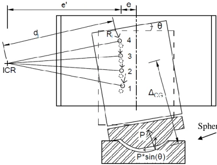
Eccentric Loading on Studs
When the repair method is implemented on a bridge, it is possible that the headed studs
may experience eccentric loading or an induced moment. To validate the performance under these
conditions, two samples were fabricated with a stud offset (e) of 50 mm and 100 mm from the
center of the web plate (Fig. 6). The UHPC panels were cast in the middle of the web plate similar
to the benchmark specimen. Since the UHPC panels were centered and the studs were offset, a
moment was introduced onto the studs. Rotation of the panels was allowed through the spherical