FLOW CONTROL OF HYDROGEN FUEL IN PEM FUEL CELL
USING SOFT COMPUTING TECHNIQUES
M. QAISERa, A. B. ASGHARa, M. H. JAFFERYa, M. Y. JAVAIDa, M. S. KHURRAMb,*
a
Department of Electrical and Computer Engineering, COMSATS University Islamabad, Lahore Campus, Lahore, Pakistan
b*
Department of Chemical Engineering, COMSATS University Islamabad, Lahore Campus, Lahore, Pakistan
Fuel cells transform the chemical energy of hydrogen directly into electrical energy without ignition or thermal processes. Their behavior is defined based on electrochemistry and thermodynamics that involves complex computations in their mathematical model. This problem of modeling can be resolved by using soft computing techniques. Fuel cells are effective, versatile and silent devices that can provide power to many applications¸ from portable electronic devices to automobiles, to electrical grids across the nation. Due to the nonlinear process of a fuel cell, fuzzy logic, neural network, and Neuro-fuzzy controllers are suitable for regulating input gasses flow rate to get appropriate electrical power according to load demand. This paper describes aMATLAB / Simulink model of 1KW, 28.8V DC power PEM fuel cell for controlling hydrogen flow rate to the fuel cell stack using fuzzy logic, neural network, and Neuro-fuzzy controllers. The output performance of controllers is compared based on their efficiency and utilization. Simulation results showed that the Neuro-Fuzzy controller provides good performance for the purging process of hydrogen.
(Received September 7, 2020; Accepted January 18, 2020)
Keywords: Proton exchange membrane fuel cell, Fuzzy logic controller, Adaptive neural network, Artificial neuro-fuzzy inference system, Non-linear dynamic model,
Hydrogen flow rate
1. Introduction
Proton exchange membrane fuel cells are also regarded as polymer electrolyte membrane fuel cell (PEMFC). Today, there is a lot of eagerness about using alternative power resources and to increase energy production to meet worldwide needs. Reservoirs currently available globally for fossil fuels (oil, coal, and gas) can only meet the energy demands within the next 100 years[1]. There are major issues around the world about an inadequate and contaminated generation of power induced by systems relying on fossil fuel. One preferred solution is to switch to clean and efficient renewable energy sources such as wind, photovoltaic technology and fuel cells based on hydrogen, etc. As the world tries to create alternative ways of generating pure and pollution-free power, fuel cells are evolving as a successful way of producing power[2]. Hydrogen power and fuel stacks are the most successful renewable and green energy sources from the future perspective as they have almost zero carbon release and produce less environmental pollution[3]. It can provide sustained power to systems with an efficiency of more than 60% which is much greater than the efficiency of traditional fuels[4]. Fuel cells are termed as an attractive substitute for power systems running on reservoirs of fossil fuels because they are highly environment-friendly without toxic by-products because hydrogen fuel is a clean energy source[5]. Fuel cells can be used for a variety of applications based on their type,ranging from small power watt (W) to large power megawatts (MW) applications[6]. They have been identified as an attractive source for the generation of energy in automobiles, distributed production of power and automated applications[7]. Various methods are present in literature for controlling hydrogen flow in fuel cell
*
but all those methods require a lot of complex computations and don’t provide desired output[8]. Significant work is done on the modeling of 1.2W PEM fuel cell by using the fuzzy logic controller (FLC) for the regulation of voltage in presence of fluctuations which is further compared with the performance of proportional-derivative-integral (PID) controller[9]. Na Woon Ki investigated that linear control strategies can't accurately regulate fuel cells because of the nonlinear characteristics of chemical processes. Nonlinear based control schemes provide the best solution for these highly nonlinear systems[10].
Some work is done on the modeling of high-temperature fuel cells with FLC for control of hydrogen flow[11]. Literature shows that the current PEMFC technology does not have adequate performance, efficiency, cost and flexibility to replace internal combustion engines[12]. This means that fuel cells have to lower their costs and improve their performance to get better results than combustion engines. In the control aspect, the efficiency of a fuel cell is compared by using FLC and PID controller and it was observed that electricity produced in presence of FLC is 37% which improves14.67% efficiency when a typical PID controller is used[13].Some researchers controlled the flow of hydrogen by using PID, fractional order PID (FOPID) and FLC + PID. These prototypes are used for controlling the output power of the PEMFCs by indirectly controlling the flow rate of hydrogen present at the input[14]. Kisacikoglu et al. have integrated the fuel control algorithm into the power-based modules and used eighty fuzzy rules[15]. He observed that PEMFC is a nonlinear system, so it is very appropriate to use FLC for coping with the control problems of a fuel cell. The design model proposed in[16] comprises strong control of fuel cell, construction of gas reformer and Fuzzy Logic for controlling the hydrogen flow rate of active load variation current. Most of the researchers have focused on the control and dynamic modeling of fuel cells. But due to the nonlinear behavior of PEMFC, control issues are resolved by using FLC. Fuzzy inference system (FIS) is used in [17] for control of temperature and power in PEM fuel cells. To achieve an appropriate optimal system, Almeida presented an artificial neural network (ANN) oriented approach for the PEMFC[18]. The goal [19]is to conduct a literature review of adaptive neural-based regulation of proton exchange membrane fuel cells. In the model[20], an adaptive neural network regulation with feedback linearization is built.
This research aims to model a 1KW PEM fuel cell with soft computing techniques to control the PEMFC for the regulation of constant output voltage. For this substructure, FLC, artificial neuro-fuzzy inference system (ANFIS) and ANN are developed to control the input hydrogen flow of PEM fuel cell.
2. Experimental materials and methods
The basic structure and performance of fuel cells should be considered to study the basic model of a fuel cell. A general structure of a fuel cell is shown in Fig.1.
Fig.1.Working Principle of PEM fuel cell[21].
There are several individual cells in a fuel cell that are lumped together to create a stack of fuel cells. In each cell, there is a cathode, an anode and an electrolyte layer[22]. Electrolyte present
in PEMFC doesn't allow electrons to pass through it as it supports the movement of positive ions only, which forces the electrons to pass through the load and produce an electric current. When a fuel, rich in hydrogen, like pure natural gas or sustainable biofuels penetrates the stack of a fuel cell, it reacts with oxygen (i.e. atmospheric air) at the cathode electrochemically to generate electrical power, heat, and water[23].
The power generated in PEM fuel cells can be interpreted by taking into account the chemical reactions taking place at the electrodes of a fuel cell.
Reaction at Anode H2 2H + + 2e- (Oxidation Process) Reaction at Cathode 1 2 O2 +2H + + 2e-H2O (Reduction Process)
The basic architecture is explained through a block diagram shown in Fig.2.
Fig.2. Schematic overview of the proposed Model.
2.1. V-I characteristics of fuel cell
The detailed characteristics of a PEM fuel cell are explained through its polarization curve in Fig.3.
Fig.3. Polarization curve of PEM fuel cell[24].
The V-I characteristics of fuel cell diverge from the optimal one because of different losses present in it such as activation losses, ohmic losses, and concentration losses.
Due to the presence of these losses, the output of fuel cell is reduced which doesn't meet up the load demands. For such purpose, a boost converter is used to step up the output to a level that is required by the load[25].
As fuel cells are very thick, they are lumped together in series to produce higher voltages according to the load demand. A single fuel cell gives almost 0.6V with a current density of 0.4A/cm2. So, the number of cells required for 1KW, 28.8V PEM fuel cell is
Cells required for FC stack = Desired Voltage Voltage per cell =
28.8
0.6= 48 cells 1KW, 28.8V PEM fuel cell will give current of Power
Voltage = 1000
28.8 = 35A. Current required per cell = Output Current
No. of cells = 35
48 = 0.729A Area per cell = Current required per cell
Current Density = 0.729
0.4 = 1.8225 cm
2
Total Area of FC stack = No. of cells × Area required per cell
= 48 × 1.8225= 87.48 c
3. Simulation and results 3.1. PEMFC DATASET
In this research, data required for designing of non-linear feedback controllers is collected by using the proposed model of PEMFC with the regulator. The current required by the load is used as an input while the flow rate of hydrogen is taken as an output. Ten thousand values are taken in the dataset which is divided into training and testing data. 70% of the total data is used for training while 30% is used for the testing of controllers. Training data provides basic information about the proposed model, and testing data vary from training data but have attributes of training data. The testing data is used to check the model's output for such input values which are not trained.
3.2. Control schemes for fuel cell
A closed-loop or feedback system is used for controlling hydrogen flow in PEMFC. In this system, an error signal (the difference between the input signal and the output or feedback signal) generated is supplied to the designed controller for the minimization of error and to get the desired value at the output. FLC, ANN, and ANFIS controllers are used for controlling the flow of hydrogen for the regulation of current from the fuel cell stack to the load and compared in table 5.
3.2.1. Designing FLC based Controller
FLC is a type of controller that deals with complex and non-linear features of PEMFC. The working principle of FLC is shown in Fig.4. For the implementation of such a controller, behaviorof the system is analyzed to create fuzzy sets of input and output variables of the hydrogen flow rate. The target variable is then de-fuzzified to a crisp variable to generate the desired control response by using IF-THEN rules between input and output fuzzy sets. Nine evenly distributed Gaussian membership functions (MFs) are used for the fuzzification of input and output variables. Mamdani type inference engine is used to create a logical conclusion depending on the fuzzy rules that encrypt the knowledge of IF-THEN statements. Fuzzified inputs are then transferred to the inference engine to apply rule base on them. The centroid method is used for defuzzification to create qualitative results in the form of a crisp set for defined fuzzy sets.
Fig.4. The architecture of a fuzzy logic controller.
For designing of FLC, MFs are required for the input and output variable. Fig.5 and Fig.6 show nine Gaussian membership functions for input current and output flow rate.
Fig.5.MFs plot for input in FIS.
Fig.6.MFs plot for output in FIS.
Flow control of PEMFC is done by connecting FLC in the feedback of the proposed model for flow control of hydrogen. MATLAB and Simulink results are shown in Fig.7 and Fig.8.
Fig.7. MATLAB plot of PEMFC with FLC.
Fig.8. Simulink plot of PEMFC with FLC.
3.2.2. Designing ANFIS based Controller
ANFIS is a hybrid soft computing learning technique that implements FIS in the structure of adaptive networks. The basic architecture of ANFIS is shown in Fig.9. It can take advantage of two machine learning techniques i.e. the fuzzy logic and neural networks which makes it an accurate and efficient controller for non-linear systems[26]. By the combination of these techniques, ANFIS gives an adequate outcome quantifiably and analytically which either includes the human knowledge-based decision making of the fuzzy system or the capabilities of the ANN system. This method utilizes FLC to convert the inputs into the required outcome utilizing strongly
interlinked ANN computing components and data connections weighted to transform mathematical inputs into outputs.
Single input and output are considered for controlling the flow of hydrogen for PEM fuel cells. Modeling of a single input based ANFIS system is designed to get the appropriate current required for the load.
Fig.9. Architecture of ANFIS.
Here, x is the input with two fuzzy sets A1 and A2. The number of MFs should be equal to the number of rules as different rules cannot share the same output MFs. For 1st order Sugeno model, two IF-THEN rules are defined.
Rule-1: if ‘x’ is A1 then f1=p1x+r1 Rule-2: if ‘x’ is A2 then f2=p2x+r2
f1 and f2 are the outputs defined by the Fuzzy rule in the Fuzzy region. The pi and ri are designed parameters that are found during the learning or training process. In the above ANFIS architecture, the circle shows a fixed node while the adaptive node is indicated by the square.
ANFIS consists of five layers. The first layer is called the fuzzification layer that extracts the input values and defines their membership functions. All the nodes are adaptive i.e. all the weights are updated during the training process. Different MFs can be considered such as Gaussian, trapezoidal, triangular or bell-shaped. The bell-shaped MF was selected due to its minimum root mean square error (RMSE) and can be expressed as;
𝜇(𝑥)𝑖 = 1 1+[(𝑥−𝑐𝑖 𝑎𝑖 ) 2 ]𝑏𝑖 (1)
i=1,2, where 𝑎𝑖, 𝑏𝑖, 𝑐𝑖 are parameters of bell-shaped MF.
The second layer consists of fixed nodes. They fuzzify the given inputs by using AND operation. This node is labeled with pie(∏) and behaves as a multiplier. The output of this layer is given as;
𝑊𝑖= 𝜇(𝑥)𝑖∗ 𝜇(𝑥)𝑖+1i=1,2,3, (2)
This layer is known as the participation layer.
The third layer consists of fixed nodes that are denoted by N to indicate their normalized firing strength. The output of the ith node is given by;
𝑊 𝑖 ̅̅̅̅̅ = 𝑊𝑖
𝛴𝑊𝑖i=1,2,3 (3)
The nodes of the fourth layer are adaptive with crisp output. This layer is known as the defuzzification layer. The output of this layer is simply the product of normalized firing strength and first-order fuzzy rule.
𝑊 𝑖
̅̅̅̅̅ ∗ 𝑓𝑖= 𝑊 ̅̅̅̅̅(𝑝𝑖 𝑖𝑥 + 𝑟𝑖)i=1,2,3 (4)
The fifth layer is a single non-adaptive node indicated with sigma (𝛴). It adds up all the incoming signals and known as the output layer.
𝑓 = 𝛴𝑊 ̅̅̅̅̅ ∗ 𝑓𝑖 𝑖= 𝛴𝑊𝑖∗ 𝑓𝑖
𝛴𝑊𝑖 i=1,2,3 (5)
The training algorithm of ANFIS is a combination of two methods i.e. least square method and gradient descent method.It uses a hybrid algorithm approach because it converges at the fastest rate to provide highly efficient results. The training process of ANFIS starts by defining fuzzy sets for each input variable along with their MFs. All the data provided to ANFIS for training passes to the neural network, which modifies the input variable and determines the relationship between input and output variable to minimize the training error RMSE.
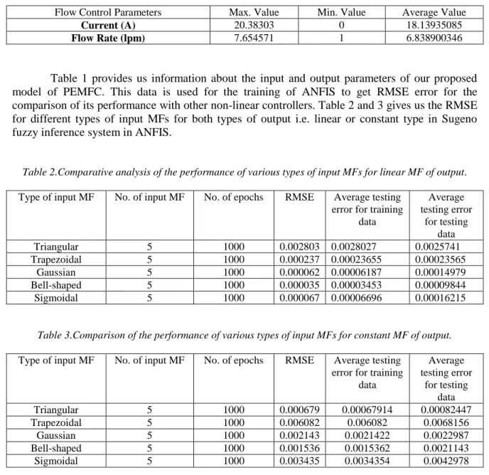
Table 1.Statistical properties of flow control data for the design of ANFIS.
Flow Control Parameters Max. Value Min. Value Average Value
Current (A) 20.38303 0 18.13935085
Flow Rate (lpm) 7.654571 1 6.838900346
Table 1 provides us information about the input and output parameters of our proposed model of PEMFC. This data is used for the training of ANFIS to get RMSE error for the comparison of its performance with other non-linear controllers. Table 2 and 3 gives us the RMSE for different types of input MFs for both types of output i.e. linear or constant type in Sugeno fuzzy inference system in ANFIS.
Table 2.Comparative analysis of the performance of various types of input MFs for linear MF of output. Type of input MF No. of input MF No. of epochs RMSE Average testing
error for training data Average testing error for testing data Triangular 5 1000 0.002803 0.0028027 0.0025741 Trapezoidal 5 1000 0.000237 0.00023655 0.00023565 Gaussian 5 1000 0.000062 0.00006187 0.00014979 Bell-shaped 5 1000 0.000035 0.00003453 0.00009844 Sigmoidal 5 1000 0.000067 0.00006696 0.00016215
Table 3.Comparison of the performance of various types of input MFs for constant MF of output. Type of input MF No. of input MF No. of epochs RMSE Average testing
error for training data Average testing error for testing data Triangular 5 1000 0.000679 0.00067914 0.00082447 Trapezoidal 5 1000 0.006082 0.006082 0.0068156 Gaussian 5 1000 0.002143 0.0021422 0.0022987 Bell-shaped 5 1000 0.001536 0.0015362 0.0021143 Sigmoidal 5 1000 0.003435 0.0034354 0.0042978
Fig.10. Training error of ANFIS with 1000 epochs.
Fig.11. MFs plot of current in ANFIS for linear output.
70% of original data used for training results into error shown in Fig.10 for 1000 iterations. Training and testing of ANFIS give out MFs of Sugeno type inference engine. Bell-shaped input MFs for linear type output is shown in Fig.11.
Fig.13. Simulink plot of PEMFC with ANFIS.
MATLAB and Simulink results found after connecting ANFIS in feedback with the PEMFC are shown in Fig.12 and 13.
3.2.3. Designing ANN-based Controller
ANN follows the working principle of the human brain. ANN with 'i' number of inputs is shown in Fig.14. They are regarded as an appealing and strong method for the modeling of non-linear systems such as proton exchange membrane fuel cell[27].
Fig.14. The architecture of ANN with 'i' inputs.
For controlling flow rate of hydrogen, a multilayer feedforward back propagation artificial neural network is used with the Levenberg-Marquardt learningmethod[28].It is an easy and fast learning algorithm that replicates the techniques used by Newton. The backpropagation method reduces the mean squared error by altering the weights of the network[29].
Following steps should be taken for the implementation of Neural Network[30]: Selection of network architecture
Selection of Training algorithm Training of neural network Validation of network operation
Given the ANN model is 3 layered structure with one hidden layer. The hidden layer consists of 10 neurons. This layer has a hyperbolic sigmoid transfer function of the form
𝑓(𝑢) = 1
1+ 𝑒−𝑑𝑢 (6) where 'd' is the parameter of slope and 'u' is the value from the input layer. This non-linear transfer function in the hidden layer helps in the dynamic modeling of fuel cells and gives linear output.
The designing of flow rate controller for PEM fuel cells with the learning process of the neural network provided effective results better than the fuzzy logic controller. The learning parameters of the neural network such as training rate, No. of epochs, etc. are listed in Table 4.
Table 4.Parameters for the output flow rate of PEM fuel cell in training of ANN.
Maximum No of epochs to train 2000
Performance Goal 2e-8
Maximum Validation failures 10
Least performance gradient 1e-7
Training rate 0.001
The proportion of increasing training rate 10 The proportion of decreasing training rate 0.1
Epochs between displays 20
The maximum time is taken for the learning process inf
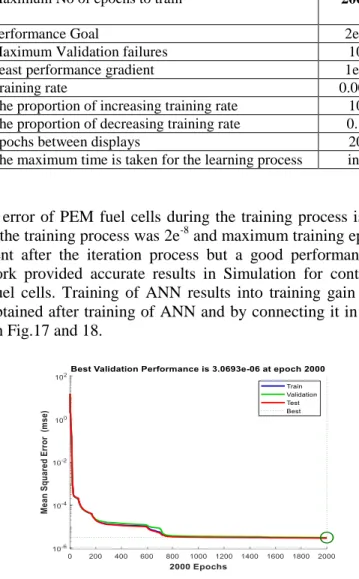
The training error of PEM fuel cells during the training process is shown in Fig.15. The performance goal of the training process was 2e-8 and maximum training epochs were 2000. Some error was still present after the iteration process but a good performance was achieved. This trained neural network provided accurate results in Simulation for controlling of flow rate of hydrogen in PEM fuel cells. Training of ANN results into training gain and gradient shown in Fig.16 and results obtained after training of ANN and by connecting it in the proposed model of PEMFC are shown in Fig.17 and 18.
Fig.16. Plot for gradient and training gain for the flow rate of PEM fuel cell.
Fig.17. MATLAB plot of PEMFC with ANN.
4. Discussion and comparison of results
Table 5 demonstrates the comparison of the efficiency of hydrogen flow control with FLC, ANN, and ANFIS scheme.
ANFIS provides us with the best trade-off between neural and fuzzy systems, offering flexibility and smoothness but limiting computational complexity. RMSE is found during the training process of data in ANFIS which is least in case of bell-shaped MF for input variable with linear type MF for output.
ANN learning process will generate the output even if the data is missing or even if one or more network cells are corrupted. But, reducing the network to some value of the sampling error means that the training is complete, which does not provide us the best results. The error is found during the Levenberg-Marquardt learning process with 2000 epochs in the case of ANN.
Even for nonlinear complex systems, FLC uses simple mathematical rules, but simulation takes a long time and results in poor accuracy.RMSE with FLC is calculated by comparison of the desired output with the output of the Mamdani inference engine for the corresponding values of input. Absolute error is then found by subtraction of actual and desired output. The average of the absolute error provides MSE resulting in RMSE.
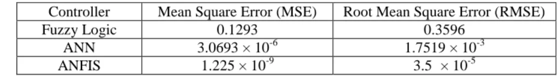
Table 5.Performance analysis of proposed approaches.
Controller Mean Square Error (MSE) Root Mean Square Error (RMSE)
Fuzzy Logic 0.1293 0.3596
ANN 3.0693 × 10⁻⁶ 1.7519 × 10⁻³
ANFIS 1.225 × 10⁻⁹ 3.5 × 10⁻⁵
5. Conclusion
In this paper, a complete mathematical and Simulink model is designed for PEM fuel cells. This model controlled the input flow of hydrogen using different soft computing techniques which handled the non-linear behavior of PEM fuel cell. The performance of the system's output power is evaluated by comparing its response with fuzzy logic, artificial neural network (ANN) and adaptive neuro-fuzzy inference system (ANFIS). ANN can map non-linear interactions between input and output, resulting in better outcomes than fuzzy logic, but not better than ANFIS.
As ANFIS is a hybrid controller (a combination of fuzzy logic and ANN) so, the results of the simulation showed that ANFIS has achieved a minimum RMSE error. Performance evaluation and graphs of Simulink and MATLAB indicated that this controller is more efficient for our proposed system. This research can be enhanced in the future by experimental testing in a realistic PEM fuel cell system along with hydrogen flow control with various techniques such as integral sliding mode control (ISMC), recurrent neural network (RNN), Granular extension of the Sugeno type fuzzy model (G-FIS) and Granular neural networks (GNN).
References
[1] L. Wang, A. Husar, T. Zhou, H. Liu, International journal of hydrogen energy28, 1263(2003).
[2] T. Yalcinoz, M. S. Alam, International Journal of Hydrogen Energy33, 1932(2008). [3] C. Spiegel, PEM fuel cell modeling and simulation using MATLAB, Elsevier, 2011. [4] I. Dincer, Hydrogen and fuel cell technologies for sustainable future,Jjmie, 2, 2008. [5] R. Boddu, U. K. Marupakula, B. Summers, P. Majumdar, Journal of Power Sources 189, 1083(2009).
[6] M. Boaventura, J. M. Sousa, A. Mendes, International Journal of Hydrogen Energy36, 9842 (2011).
journal of hydrogen energy 39, 15158 (2014).
[8] M. Grötsch, Nonlinear analysis and control of PEM fuel cells, 2010.
[9] N. E. Benchouia, A. Derghal, B. Mahmah, B. Madi, L. Khochemane, E. H. Aoul, International Journal of Hydrogen Energy 40, pp. 13806(2015).
[10] W. K. Na, B. Gou, IEEE Transactions on Energy Conversion 23, 179 (2008). [11] C. Zhang, Z. Liu, X. Zhang, S. H. Chan, Y. Wang, Energy95, 425 (2016).
[12] L. A. M. Riascos, D. D. Pereira, in ABCM Symposium Series in Mechatronics, 2010. [13] S.-R. Huang, C.-Y. Lin, C.-C. Wu, S.-J. Yang, International Journal of hydrogen energy33, 5205 (2008).
[14] Y. Qi, M. Thern, M. Espinoza-Andaluz, M. Andersson, Energy Procedia159, 54(2019). [15] M. C. Kisacikoglu, M. Uzunoglu, M. S. Alam, in 2007 IEEE vehicle power and propulsion conference, 2007.
[16] A. Thomya, Y. Khunatorn, Energy Procedia 9, 186 (2011).
[17] G. S. Nhivekar, S. S. Nirmale, R. R. Mudholker, International Journal of Engineering, Science and Technology3, 2011.
[18] P. E. M. Almeida, M. G. Simoes, in 38th IAS Annual Meeting on Conference Record of the Industry Applications Conference, 2003., 2003.
[19] C. Lin-Kwong-Chon, B. Grondin-Pérez, J.-J. A. Kadjo, C. Damour, M. Benne, Annual Reviews in Control, 2019.
[20] A. Abbaspour, A. Khalilnejad, Z. Chen, International Journal of Hydrogen Energy41, 20385(2016).
[21]S. Kolar, Modeling, system analysis and control of a proton exchange membrane fuel cell, 2016.
[22] A. W. Al-Dabbagh, L. Lu, A. Mazza, International Journal of Hydrogen Energy35, 5061 (2010).
[23] A. S. A. A. Hamaad, M. Tawfik, S. Khattab, A. Newir, Procedia Environmental Sciences37, 564 (2017).
[24] W. R. W. Daud, R. E. Rosli, E. H. Majlan, S. A. A. Hamid, R. Mohamed, T. Husaini, Renewable Energy113, 620 (2017).
[25] M. Hatti, M. Tioursi, International Journal of Hydrogen Energy34, 5015 (2009). [26] S. Rezazadeh, M. Mehrabi, T. Pashaee, I. Mirzaee, Journal of mechanical science and technology 26, 3701 (2012).
[27] I. Zamora, J. I. San Martı́n, J. J. San Martı́n, V. Aperribay, P. Eguı́a, in International Conference on Renewable Energies and Power Quality (ICREPQ’09), Valencia, 2009. [28] K. Mammar, A. Chaker, International Journal of Computer Science Issues (IJCSI)9, 244 (2012).
[29] A. Morán-Durán, A. Martı́nez-Sibaja, J. P. Rodrı́guez-Jarquin, R. Posada-Gómez, O. S. González, Processes 7, 434 (2019).
[30] A. Sari, A. Balikci, S. Taskin, S. Aydin, in 2013 8th International Conference on Electrical and Electronics Engineering (ELECO), 2013.