HIGH EFFICIENCY PHOTOVOLTAIC POWER CONTROLLER USING
MPPT AND BUCK BOOST CONVERTER
Raphin C A 1, George T V2
1
Electrical and Electronics , KMEA, Kerala , India
2
Electrical and Electronics, KMEA, Kerala, India
Abstract— The maximum power point tracking (MPPT) is used in photovoltaic system to maximize the photovoltaic array output power , irrespective of temperature , IR radiation, conditions and electrical characteristics of the load. A new MPPT system is developed consisting of DC to DC converter, which is controlled by microcontroller based unit. There are two charging stages for the proposed PV charger. At the beginning of charging process, a continuous MPPT charging scheme is adopted. When the State of Charge (SOC) of battery reaches the given condition. a pulse current charging scheme with adaptive rest period applied to obtain an average charging current with an exponential profile. During the charging period MPPT function is retained to achieve high charging efficiency. Over charging of the battery can be avoided using the pulse charging scheme with adaptive rest period. The main difference between the method used in the MPPT system and other techniques used in the past is that the PV array output power is used to directly control the DC to DC converter, thus reducing the complexity of the system . In addition, we attempt to design the MPPT by using the algorithm of a selected MPPT method which is “Perturb and Observe “and implement it by using a DC– DC Converter. We have found various types of DC-DC converters .Among them we have selected the most suitable converter which is “BUCK-BOOST” converter , for our desing.PV generation system generally use a microcontroller based charge controller connected to a battery and the load. A charge controller is used to maintain proper charging voltage on the batteries. As the input voltage from the solar array, the charge controller regulates the charge to the batteries preventing any overcharging. So a good, solid and reliable PV charge controller is a key component of any PV battery charging system to achieve systems maximum efficiency. Whereas microcontroller based designs are able to provide more intelligent control and thus increases the efficiency of the system. Index Terms— MPPT, State of Charge, Pulse charging scheme, Perturb and Observe , Buck Boost converter etc…
1. INTRODUCTION
In order to tackle the present energy crisis one has to develop an efficient manner in which power has to be extracted from the incoming solar radiation. The power conversion mechanisms have been greatly reduced in size in the past few years. The development in power electronics and material science has helped engineers to come up very small but powerful systems to withstand the high power demand. But the disadvantage of these systems is the increased power density. Trend has set in for the use of multi-input converter units that can effectively handle the voltage fluctuations. But due to high production cost and the low efficiency of these systems they can hardly compete in the competitive markets as a prime power generation source. The constant increase in the development of the solar cells
manufacturing technology would definitely make the use of these technologies possible on a wider basis. The use of the newest power control mechanisms called the Maximum Power Point Tracking (MPPT) algorithms has led to the increase in the efficiency of operation of the solar modules and thus is effective in the field of utilization of renewable sources of energy.
PV generation systems generally use a microcontroller based charge controller connected to a battery and the load. A charge controller is used to maintain the proper charging voltage on the batteries. As the input voltage from the solar array, the charge controller regulates the charge to the batteries preventing any overcharging. So a good, solid and reliable PV charge controller is a key component of any PV battery charging system to achieve systems maximum efficiency. Whereas microcontroller based designs are able to provide more intelligent control and thus increases the efficiency of the system.
2. MAXIMUM POWER POINT TRACKING Maximum power point tracking has been shown to increase the efficiency of the system by approximately 30% over charge controllers that do not implement MPPT. [2,3] In addition, as the battery charges the voltage will change as it passes through several charging states which would create further inefficiencies in the absence of a charge controller. In this project, the charge controller should be able to monitor voltages from both the photovoltaic array and the battery in order to determine these charging states and maintain maximum efficiency. To illustrate a potential scenario, consider if the goal of the system is to charge a 12 V battery but the maximum power point occurred at a panel voltage of 15 V.
If the panel were connected directly to the battery, it would pull the panel voltage down to 12, which the graph would clearly show is inefficient and operating below the maximum power point. Rather than allow this energy to be wasted, the charge controller allows the panel to continue to operate at the MPP but uses DC-to-DC converters to compensate for the difference in voltage needed. This prevents significant losses and allows the system to take advantage of the valuable power that is produced in the solar array there are several common methods that are used to implement maximum power point tracking.
2.1 EFFECTS OF SOLAR IRRADIANCE ON MPPT There are two key parameters frequently used to characterize a PV cell. Shorting together the terminals of the cell, the photon generated current will follow out of the cell as a short-circuit current (Isc). When there is no connection to the PV cell (open-circuit), the photon generated current is
shunted internally by the intrinsic p-n junction diode. This gives the open circuit voltage (Voc). The PV module or cell manufacturers usually provide the values of these parameters in their datasheet In a PV cell current is generated by photons and output is constant under constant temperature and constant incident radiation of light. Varying the irradiation we can get different output levels. .
The current voltage relationship of a PV cell is given below,
……… (2.1)
To a very good approximation, the photon generated current, which is equal to is directly proportional to the irradiance (G), the intensity of illumination, to PV cell. If Isc (Go) is the photo current at irradiance Go=1000W/m2 at the air mass AM = 1.5, then the photon generated current at any other irradiance, G (W/m2), is given by,
……… (2.2) So, the equation for varying irradiance,
………. (3.3.)
Fig 2.1: I-V curve with different irradiance
Fig: 2.2 P-V curves with different irradiance
The PV cell output is both limited by the cell current and the cell voltage, and it can only produce a power with any combinations of current and voltage on the I-V curve. As in Figure: 2.2 the P-V curve shifts with different irradiance so the MPP also shifts. Now, as the I-V curve of a PV cell changes with different irradiance so it reveals that the amount of power produced by the PV module varies greatly depending on its irradiance. It is important to operate the system at the MPP of PV module in order to exploit the maximum power from the module.
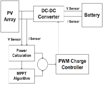
3. PROPOSED CONVERTER TOPOLOGY In this paper , the Maximum Power Point Tracker (MPPT) will be implemented by using a microcontroller that is programmed to execute the desired algorithm. The program will control the charge controller of the PV array by sensing the panel voltage (V) and current (I) and the battery voltage of to determine the single operating point where the values of current (I) and voltage (V) result in a maximum power output. This is the Maximum Power Point (MPP). The goal of the MPPT is to match the impedance of the battery to the optimal impedance of the panel.
After taking the measurements of voltage and current, and decides the tracking algorithm (Perturb and Observe) which is the heart of the MPPT controller. The algorithm that is used is written using C# programming language on an interface known as Micro C. The program built generates a “.hex” file which is burned onto the microcontroller by means of a lock burner.
Fig -3.1: Proposed converter design
3.1 DC – DC CONVERTER CONTROL
A charge controller or charge regulator limits the rate at which electric current is added to or drawn from electric batteries. It prevents overcharging and may prevent against overvoltage, which can reduce battery performance or lifespan, and may pose a safety risk. It may also prevent completely draining ("deep discharging") a battery, or perform controlled discharges, depending on the battery technology, to protect battery life. In simple words, Solar Charge controller is a device, which controls the battery charging from solar cell and also controls the battery drain by load. The simple Solar Charge controller checks the battery whether it requires charging and if yes it checks the availability of solar power and starts charging the battery.
Whenever controller found that the battery has reached the full charging voltage levels, it then stops the charging from solar cell. On the other hand, when it found no solar power available then it assumes that it is night time and switch on the load. It keeps on the load until the battery reached to its minimum voltage levels to prevent the battery dip-discharge. Simultaneously Charge controller also gives the indications like battery dip-discharge, load on, charging on etc.
In this paper we are using microcontroller based charge controller. Microcontroller is a kind of miniature computer containing a processor core, memory, and programmable input/output peripherals.
The Functions of a microcontroller in charge controller are: Measures Solar Cell Voltage.
Measures Battery Voltage.
Decides when to start battery charging. Decides when to stop battery charging. Decides when to switch on the load. Decides when to switch odd the load.
Most importantly in this thesis, microcontroller also tracks the MPP of the output power.
3.2 MPPT CONTROL SCHEME
Photovoltaic (PV) energy is the most important energy resource since it is clean, pollution free, and inexhaustible. In recent years, a large number of techniques have been proposed for tracking the maximum power point (MPP). Maximum power point tracking (MPPT) is used in photovoltaic (PV) systems to maximize the photovoltaic array output power, irrespective of the temperature and radiation conditions and of the load electrical characteristics the PV array output power is used to directly control the dc/dc converter, thus reducing the complexity of the system. The method is based on use of a Incremental conductance of the PV to determine an optimum operating current for the maximum output power.
In perturb and observe method the array terminal voltage is always adjusted according to the MPP voltage it is based on the incremental and instantaneous conductance of the PV module
Fig 3.2- MPPT Control
Fig shows that the slope of the P-V array power curve is zero at The MPP, increasing on the left of the MPP and decreasing on the Right hand side of the MPP. The basic equations of this method are as follows.
At MPP …………( 3.2.1) Left of MPP, ………….(3.2.2) Right of MPP, ………. (3.2.3)
Right of MPP Where I and V are P-V array output current and voltage respectively. The left hand side of equations represents P&O algorithm of P-V module and the right hand side represents the instantaneous conductance. When the ratio of change in output conductance is equal to the negative output conductance, the solar array will operate at the maximum power point.
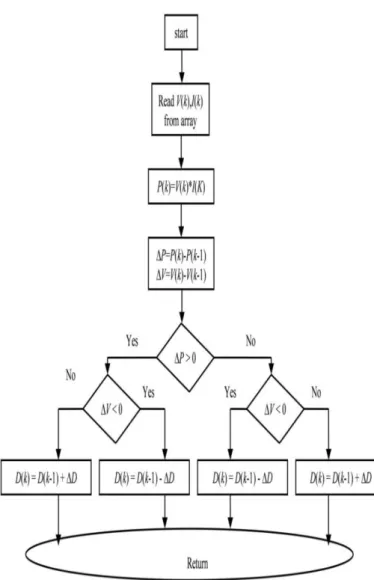
Flow chart for perturb & observe
4. SIMULATION AND RESULTS
Fig 4.1 Matlab/Simulink model of MPPT control
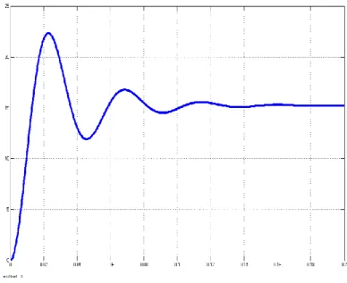
Fig 4.2 MPPT power output graph
4.1 HARDWARE DESCRPTION
The microcontroller that will be used in this system is PIC16F886A. It is a 28 pin IC. It has a memory of 368 bytes and external programmable memory (EEPROM) of 256 bytes. The microcontroller senses both the panel and battery voltages and takes decisions to activate different components of the circuits such as, transistors, relays and LED indicators. It is powered up by the lead-acid battery connected to it through a voltage regulator (LM7805) which converts the 12V into 5V and is connected to a RESET (pin 1). The microcontroller is also powered by a 5V supply at pin 20 and ground at pin 8 and 19.
Solar panel voltage Voc = 21 V Solar panel current Ish = 8.6
Converter output voltage = 13.5 -15 V
Fig 4.3 Hardware
5. CONCLUSIONS
This study presents a simple but efficient photovoltaic system with maximum power point tracker. Description of each component like solar panel, DC-DC converter and charge controller is presented here of I-V characteristics for different irradiance, load and temperature are shown here. As, our aim was to design a system which can extract maximum output power, so we explained about maximum power point (MPP) and maximum power point tracker (MPPT). Researches for different method of algorithms for are done. For better result we compared the without MPPT method with Perturb and observe method. Perturb and observe method shows narrowly better performance. The problems solving techniques are also here. This thesis adopts the direct control method which employs the P&O algorithm but requires only two sensors (voltage sensing and current sensing) for output. This control method offers another benefit of allowing steady-state analysis of the DC-DC converter. This generator was utilized for generating the pulse signal that was compared with the signal generated from the MPPT unit to give out the gating signal to the switch. When MPPT is used there is no need to input the duty cycle, the algorithm iterates and decides the duty cycle by itself. But if MPPT had not been used, then the user would have had to input the duty cycle to the system. When there is change in the solar irradiation the maximum power point changes and thus the required duty cycle for the operation of the model also changes. But if constant duty cycle is used then maximum power point cannot be tracked and thus the system is less efficient. There is a small loss of power from the solar panel side to the boost converter output side. This can attributed to the switching losses and the losses in the inductor and capacitor of the boost converter.
REFERENCES
[1]. M. G. Villalva, J. R. Gazoli, E. Ruppert F, "Comprehensive approach to modeling and simulation of
Electronics, 2009 vol. 25, no. 5, pp. 1198--1208, ISSN 0885-8993.
[2] M. G. Villalva, J. R. Gazoli, E. Ruppert F, "Modeling and circuit-based simulation of photovoltaic arrays", Brazilian Journal of Power Electronics, 2009 vol. 14, no. 1, pp. 35--45, ISSN 1414-8862.
[3].Mummadi Veerachary, "Control of TI-SEPIC Converter for Optimal Utilization of PV Power", IICPE, 2010 New Delhi.
[4].R. Sridhar, Dr. Jeevananathan, N. Thamizh Selvan, Saikat Banerjee, “Modeling of PV Array and Performance Enhancement by MPPT Algorithm", International Journal of Computer Applications (0975 – 8887) Volume 7– No.5, September 2010.
[5].Hairul Nissah Zainudin, Saad Mekhilef, “Comparison Study of Maximum Power Point Tracker Techniques for PV Systems”, Cairo University, Egypt, December 19-21, 2010, Paper ID 278.
[6.] Katherine A. Kim and Philip T. Krein, “Photovoltaic Converter Module Configurations for Maximum Power Point Operation”, University of Illinois Urbana-Champaign Urbana, IL 61801 USA.
[7].Huan-Liang Tsai, Ci-Siang Tu, and Yi-Jie Su, “Development of Generalized Photovoltaic Model Using MATLAB/SIMULINK”, Proceedings of the World Congress on Engineering and Computer Science 2008 WCECS 2008, October 22 - 24, 2008, San Francisco, USA.
BIOGRAPHIES
Raphin C A received B.E degree in Electrical and Electronics Engineering from Anna University , Chennai in 2013.Now she is pursuing MTech in Power Electronics at MG University. His main research interest includes topology control of solar power converters and distributed generations topologies.
Prof George T V received MTech from NIT, Calicut, India. He had experience with Lignite Corporation of India .Now working as a professor at KMEA college, MG University , India.