182 |
P a g e
A SECURE DIGITAL STEGANOGRAPHY BASED ON
DISCRETE WAVALET TRANSFORM
Farhanjum Khan
&
Astt.Professor- Rakesh Gill
ABSTRACT
In Steganography, the secret message is embedded in the cover work and transmitted in such a way that the
existence of secret information is undetectable. The digital images, videos, sound files and other computer files
can be used as carrier to embed the information. The project deals with a secure and high capacity based
steganography. Images taken are gray-scale digital images.
Arnold transformation is used to scramble the secret image, for improving the security level. Discrete Wavelet
Transform (DWT) is performed on images to decompose them into different frequency sub-bands. Alpha
blending is the method used for mixing cover image and secret image. Peak signal to noise ratio, mean square
error and noise cross correlation are the parameters used to check the effectiveness of the algorithm.
I. INTRODUCTION
Steganography means covered writing. Purpose of it is to hide the fact that communication is taking place. The word cover is used to describe the original, innocent message. Security is becoming more important as the amount of data being exchanged on the internet increases. Therefore to protect the data from unauthorized access, confidentiality and integrity are required. This has resulted in the fast growth of information hiding techniques [1].
Cryptography was created as a technique for securing the secrecy of communication to encrypt and decrypt data in order to keep the message secret, but sometimes it is not enough to keep the contents of message secret, it is also important to keep the existence of message secret. The technique used to implement this is known as steganography [2].
Steganography is the technique to achieve secret communication between two parties that are interested in hiding not only the content of a secret message but also the act of communicating it. To achieve this, algorithms known as steganography algorithms also known as “stego” algorithms are used, which embed the secret
information into different types of cover media like images, video, or sound, thus hiding the existence of communicated information. The altered data which is the result of embedding is known as stego-data and this must be perceptually indistinguishable from cover data [3]. The word steganography is derived from Greek words “stegos” meaning “cover” and “grafia” meaning “writing” defining it as “covered writing”. In image
steganography the information is hidden exclusively in images [2].
Cover Image: This is the original image into which required information is embedded. It is also termed as
183 |
P a g e
Stego Image: It is an image obtained by the combination of payload and cover image [4].
Cover Files Used For Steganography- Cover files represent the container of secret messages. Some characteristics of cover files will be modified, changed, or manipulated in order to hide these secret messages. The manipulations, which occur during the hiding procedure, should remain imperceptible to anyone not involved in the communication process. The appearance of cover files must remain intact after hiding the secret data.
There are many kinds of digital media such as image, audio, text, and video files that can be used as cover files in steganography. The ability of files to embed secret data depends on the availability of redundant areas within these files. Thus, the cover files represent the container of hidden data and their size determines the secret data size that can be embedded [5].
Basic Steganographic System
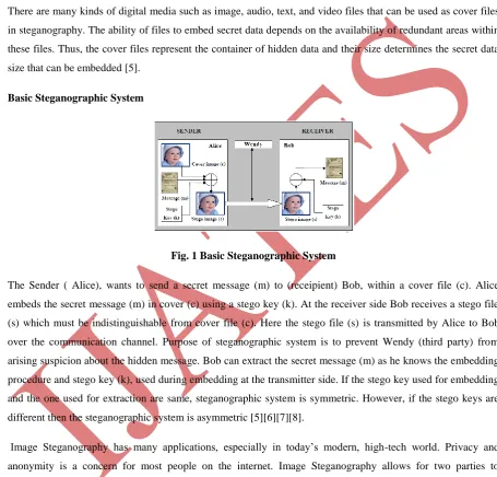
Fig. 1 Basic Steganographic System
The Sender ( Alice), wants to send a secret message (m) to (receipient) Bob, within a cover file (c). Alice embeds the secret message (m) in cover (c) using a stego key (k). At the receiver side Bob receives a stego file (s) which must be indistinguishable from cover file (c). Here the stego file (s) is transmitted by Alice to Bob over the communication channel. Purpose of steganographic system is to prevent Wendy (third party) from arising suspicion about the hidden message. Bob can extract the secret message (m) as he knows the embedding procedure and stego key (k), used during embedding at the transmitter side. If the stego key used for embedding and the one used for extraction are same, steganographic system is symmetric. However, if the stego keys are different then the steganographic system is asymmetric [5][6][7][8].
184 |
P a g e
II. STEGANOGRAPHY Vs CRYPTOGRAPHY
Steganography is the art and science of communicating in a way that hides the existence of communication i.e. it hides the message so that it is not seen. In Cryptography a message is scrambled in a way so that it cannot be understood. It defines the art and science of transforming data into different form such that no one can read it without having access to encryption key. Cryptanalysis is the science of cracking encryption schemes i.e. finding decryption key. Plain text is the message that is in readable form i.e. (not encrypted).
Encryption: encoding the contents of the message i.e. converting it into unreadable form. Cipher text results from plain text after applying encryption key Decryption: It is the process of retrieving plain text from cipher text.
There are two general methods on which encrypting algorithms are based. First is the substitution, in which each element in the plain text is mapped into another element. In the second method of transposition, elements in the plain text are rearranged [13].
III. TYPES OF STEGANOGRAPHIC ATTACKS
Steganography attackers are the interceptors of stego files in the communication channels in order to detect hidden messages in stego files.
Passive Attack- Passive wardens just observe the communication without any interference. The passive warden only has the right to prevent or permit the message delivery. The warden is restricted from modifying the contents of stego files during the communication process. Therefore, the communication between two parties will be blocked if the warden suspects that a secret communication is taking place. Otherwise the communication will be relayed.
Simmons (1983), in the “Prisoners‟ Problem", illustrated steganography with a passive attack. Alice and Bob are arrested and thrown in two different cells. They want to develop an escape plan, but all their communication is arbitrated by a warden (Wendy). Alice and Bob must communicate in a way so as not to arouse Wendy‟s suspicion. Alice and Bob can succeed only if Alice can hide and send information to Bob in a way that Wendy does not become suspicious [6][14].
Active Attack- If the warden can modify the contents of stego files during the communication process, then the warden is known as active warden. Active attack is the process of altering stego files and introducing distortion during the communication process. In such kind of attacks, the attacker can capture and modify a stego file sent from Alice to Bob and then forward this modified file to Bob [5][6][15].
185 |
P a g e
IV. STEGANOGRAPHY TECHNIQUES
Distortion Techniques- Distortion requires the knowledge of the original cover in the decoding process. For a receiver, the embedded message is the difference between the modified cover file received (the stego file) and the original cover file [5][11].
Cover Generation Techniques - All Steganography techniques described above need cover files to be used as containers for secret data. However, for the purpose of hiding information cover generation techniques do not require cover files but instead they create stego files. [5][11].
Transform Embedding Techniques-Substitution and modification techniques are easy ways to embed information, An attacker can destroy secret information simply by applying signal processing techniques. Embedding information in the frequency domain of a signal is much more robust than embedding in time domain. This is a technique of embedding where the coefficients of message are modified in transform domain. Discrete Cosine Transform (DCT), Discrete Fourier Transform (DFT), Discrete Wavelet Transform (DWT) are the examples of transform domain techniques. Transform techniques offer superior robustness against lossy compression, scaling, rotation, cropping, adding noise, compression, depending on the properties of particular transform [11][12].
Spread Spectrum Techniques- Spread Spectrum Techniques are employed where robustness is critical. The watermark or message can be thought of as a narrowband signal encoded in a larger frequency band (cover). By spreading the energy of message across many frequency bands energy at any particular band is reduced. Therefore it becomes difficult to detect or modify the message. Error correcting codes may be employed during embedding to allow recovery even when some of the areas of stego- image may be altered or damaged[12].
V.TRANSFORMS
Wavelet Transform - A wavelet transform is the representation of a function by wavelets. The wavelets are scaled and translated copies (known as "daughter wavelets") of a finite-length or fast-decaying oscillating waveforms (known as the "mother wavelet"). Wavelet analysis is an exciting method for solving problems in engineering mathematics and physics with modern applications as signal processing, image processing, wave propagation, data compression, pattern recognition, computer graphics, Astronomy, Acoustics, Nuclear Engineering, Sub band Coding, Signal and Image Processing, Neurophysiology, Magnetic Resonance Imaging, Speech Discrimination, Optics, Earthquake Prediction, Radar, Computer and Human Vision, Data Mining and Mathematics Applications etc. In the wavelet transform an image signal can be analyzed by passing it through an analysis filter bank followed by a decimation operation. This analysis filter bank consists of a low pass and a high pass filter at each decomposition stage.
186 |
P a g e
Discrete Wavelet Transform- Discrete Wavelet Transform provides a multi-resolution analysis of real world signals and images. It decomposes signal into a set of basic functions, called wavelets. The main idea behind DWT results from multi-resolution analysis, which involves decomposition of an image in frequency channels of constant bandwidth on logarithmic scale. Image itself is considered as a two dimensional signal. DWT can be implemented as a multistage transformation. An image isdecomposed into four sub- bands denoted as LL (Low- Low), LH (Low- High), HL (High- Low), HH (High- High) at level 1 in DWT domain. LL sub- band consists of low frequency wavelet coefficients.
At level 1 DWT decomposes image into four non- overlapping multiresolution sub- bands: LLX (Approximate
sub- band), LHX(Vertical sub- band), HLX (Horizontal sub- band), HHX (Diagonal sub- band). Here LLX is
low frequency component, whereas LHX , HLX , HHX are high frequency components. Maximum energy of
images is concentrated in approximate band and amplitude of coefficient is larger than the one of detail sub-graph.
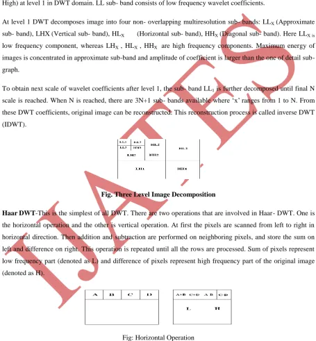
To obtain next scale of wavelet coefficients after level 1, the sub- band LL1 is further decomposed until final N
scale is reached. When N is reached, there are 3N+1 sub- bands available where „x‟ranges from 1 to N. From these DWT coefficients, original image can be reconstructed. This reconstruction process is called inverse DWT (IDWT).
Fig. Three Level Image Decomposition
HaarDWT-This is the simplest of all DWT. There are two operations that are involved in Haar- DWT. One is the horizontal operation and the other is vertical operation. At first the pixels are scanned from left to right in horizontal direction. Then addition and subtraction are performed on neighboring pixels, and store the sum on left and difference on right. This operation is repeated until all the rows are processed. Sum of pixels represent low frequency part (denoted as L) and difference of pixels represent high frequency part of the original image (denoted as H).
Fig: Horizontal Operation
187 |
P a g e
band is the low frequency sub- band and is very similar to the original image. This process described is first order 2- D Haar- DWT.
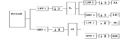
Fig. One level decomposition using two dimensional DWT
LPF1 represents low pass filtering of image rows, HPF1 represents high pass filtering of image rows, LPF2 represents low pass filtering of image columns, and HPF2 represents high pass filtering of image columns. “L” represents low frequency components and “H” represents high frequency components.
Fig. Image Recomposition
Union of four sub- bands permits to reconstruct the original image. The LL sub band comes from low pass filtering in both directions and is mostly like original image and so it is called as approximate component. The remaining sub-bands come from the combination of low and high pass filter. Components obtained using only high pass filters are called as detailed components. LH preserves vertical edge details, HL preserves horizontal edge details and HH preserves the diagonal details.
Arnold Transform
Arnold transform commonly known as cat face transform is an efficient technique for position swapping, and widely applied to image encryption. Encryption techniques also called image scrambling produces an unintelligible or disordered image from the original image, therefore used to confirm the security and improve the robustness of the steganographic scheme. Therefore the secret image should be pre-processed before embedded into the original image. The transform rearranges the position of image pixels, and if it is done several times, a disordered image can be generated. The special property of Arnold Transform is that image comes to its original state after certain number of iterations i.e. after iterating a certain numbers it returns the same pixels position as before and thereby produces the original image. . These‟ number of iterations‟ are called „Arnold Period‟ or „Periodicity of Arnold Transform‟. The periodicity of Arnold Transform (P), is dependent on
188 |
P a g e
N
2 3 4 5 6 7 8 9 10 11 12 16 24 25
Per
i
od
3 4 3 10 12 8 6 12 30 5 12 12 12 50
N
32 40 48 50 56 60 64 100 120 125 128 256 480 512
Per iod
24 30 12 150 24 60 48 150 60 250 96 192 120 384
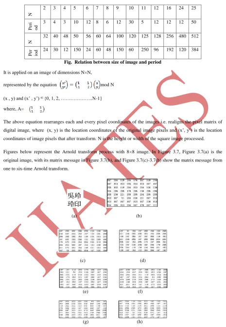
Fig. Relation between size of image and period
It is applied on an image of dimensions N×N,
represented by the equation mod N
(x , y) and (x‟ , y‟) {0, 1, 2, ………..N-1}
where, A=
The above equation rearranges each and every pixel coordinates of the images i.e. realigns the pixel matrix of digital image, where (x, y) is the location coordinates of the original image pixels and (x‟, y‟) is the location
coordinates of image pixels that after transform. N is the height or width of the square image processed.
Figures below represent the Arnold transform process with 8×8 image. In Figure 3.7, Figure 3.7(a) is the original image, with its matrix message in Figure 3.7(b), and Figure 3.7(c)-3.7(h) show the matrix message from one to six-time Arnold transform.
(a) (b)
(c) (d)
(e) (f)
(g) (h)
189 |
P a g e
(a) (b) (c) (d)Fig. Image before 20(60, 96) time Arnold transform
There in figure (a) is the 128×128 original image. Fig. 3.8(b)-(d) shows the image thorough 20/60/96 times Arnold transform. If one image iterates m steps to get scrambled state with Arnold transformation, it can restore its image with the same steps form the scrambled state by anti-Arnold transformation.
mod N
Alpha Blending
It is the way of mixing two images together to form a stego image. In this technique the decomposed components of the host image and the secret image are multiplied by a scaling factor and are added. It can be accomplished by blending each pixel from the secret image with the corresponding pixel in the cover image. The equation for executing alpha blending is as follows,
Stego Image = Cover Image + α *(Secret Image)
where,‟a‟is the scaling factor. The blending factor used in the blended image is called the "alpha."Formula of the alpha blending extraction to recover secret image is given by
Secret Image = (Stego Image – Cover Image) / α
VI. RESULT ANALYSIS
All the methods and algorithms described in project are implemented using MATLAB 7.4.0(R2007a). The experiments were performed on a PC based on 32- bit operating system with 2 GB of RAM. The work deals with gray scale cover images and binary text secret images. An experimental result shows that the optimum value of alpha at the transmitter side is 0.06 and at the receiver side it is 0.0003. The results are better when the value of standard deviation in intensity domain is taken as 3e-5 and in spatial domain as 3.8. Value of key for Arnold Transformation is taken as 20.
Peak Signal to Noise Ratio: It is the ratio of the maximum signal to noise in the stego image.
Normalized-CrossCorelation:
190 |
P a g e
Bilateral Filter
Bayes Shrink Thresholding =
Noise variance
Signal Variance :It is computed from the variance of the observed coefficients and
Table: Relationship of PSNR and NCC with alpha ( ) keeping cover image and secret image same for all values of alpha
VII. CONCLUSION
By this presented method secret image is extracted from a stego image without having cover image. The secret image is considered as noise. The algorithm was applied on a number of images of various sizes and formats.
COVER IMAGE – BARBARA (.png , 512×512) SECRET IMAGE – IMAGE 1 (.bmp , 403×327)
PSNR1 NCC1
40.6777 0.9873 0.01
34.6571 0.9750 0.02
31.1352 0.9630 0.03
28.6365 0.9512 0.04
26.6983 0.9398 0.05
25.1146 0.9286 0.06
23.7757 0.9177 0.07
22.6159 0.9070 0.08
21.5928 0.8966 0.09
20.6777 0.8864 0.1
14.6571 0.7960 0.2
191 |
P a g e
The results obtained by applying the algorithm shows that there is no size and format limitation, indicating the application to any size images and formats. Observations and analysis that secret information can be extracted without need of separate cover image also there is a trade- off between PSNR and extracted secret information visual quality.
It has been observed that PSNR and NCC decrease as the value of alpha increases. The results obtained are best
for encoding when value of alpha (parameter of embedding the watermark) is 0.06. For the decoding process, results are best when the value of alpha is 0.0003. For higher values of alpha visual
appearance of extracted secret image degrades. Secret image is extracted properly when the value of „Ln‟ (key for encrypting secret k image in Arnold Transformation) is 20. For lower values of it encryption is not proper, extraction of secret image is not proper, dissimilarity observed visually between cover image and stego image is more, and computation time is less.
The work can be enhanced for hiding picture images. The work can be extended for color images. One can further try to improve the extracted secret image quality.
REFERENCES
[1] S .K. Moon and R.S. Kawitkar, “Data security using data hiding,” International Conference on Computational Intelligence and Multimedia Applications, vol. 04, pp. 247-251, Dec. 2007
[2] T. Morkel, J.H.P. Eloff, M.S. Olivier, “An overview of image steganography,” Information and Computer Security Architecture (ICSA) Research Group Department of Computer Science, June/July 2005.
[3] Alvaro Martín, Guillermo Sapiro, and Gadiel Seroussi, “Is image steganography natural?,” IEEE Trans. on Image Processing, vol. 14, no. 12, pp. 2040-2050, Dec. 2005.
[4] K Suresh Babu et. al., “Authentication of secret information in image steganography,” pp. 1-6, Nov. 2008.
[5] Stefan Katzenbeisser, Fabien A. Petitcolas, ”Information hiding techniques for steganography and digital watermarking,” Artech House, 2000.
[6] Ingemar Cox, Matthew Miller, Jeffrey Bloom, Jessica Fridrich, Ton Kalker, ”Digital watermarking and steganography-second edition,” Burlington, MA, USA, Elsevier Inc., 2008.
[7] Chiang-Lung Liu, Shiang-Rong Liao, “High-performance JPEG steganography using complementary embedding strategy,” Pattern Recognition, vol. 41, Issue. 9pp.2945-2955, Sep. 2008.
[8] Kefa Rabah, “Steganography- The Art of Hiding Data”, Information Technology Journal,Vol.-3, Issue- 3, pp.-245-269, 2004.
[9] Harshavardhan Kayarkar, Sugata Sanyal,” A Survey on various data hiding techniques and their comparative analysis,” ACTA Technica Corviniensis, vol. 5, Issue. 3, pp. 35-40, June 2012.
[10] Nick Nabavian, “Image Steganography”, Nov. 28, 2007
[11] Pierre Moulin , Ralf Koetter,” Data-hiding codes,” Proc. IEEE, vol. 93, no. 12, pp. 2083- 2126, Dec. 2005.
[12] Zaidoon Kh. AL-Ani, A.A.Zaidan, B.B.Zaidan and Hamdan.O.Alanazi, ”Overview: main fundamentals for steganography,” Journal of Computing, vol. 2, Issue. 3, pp. 158- 165, March 2010.
[13] Eugene T. Lin and Edward J. Delp, ”A review of data hiding in digital images,” Proc. of the Image Processing, Image Quality, Image Capture Systems Conference, PICS'99, 1999.
[14] A.Joseph Raphael, Dr.V Sundaram, ”Cryptography and steganography – a survey, ” Int. J. Comp. Tech. Appl., vol. 2 (3), pp. 626-630, 2011.
[15] Simmons, G.J.,”The prisoners‟ problem and the subliminal channel, ”CRYPTO‟83, pp. 51-67, 1983.
[16] Christian Cachin, ”An information-theoretic model for steganography,” The Second International Workshop on Information Hiding, 1525, pp. 306-318, 1998.
[17] Eric Cole, ”Hiding in plain sight: steganography and the art of covert communication,” Indiana, John Wiley & Sons Inc., 2003. [18] Gregory Kipper, ”Investigator's guide to steganography,” Florida, CRC Press LLC, 2004.
[19] Max Weiss,” Principles of steganography,” Math 187: Introduction to Cryptography Professor Kevin O‟Bryant.
[20] Souvik Bhattacharyya, Gautam Sanyal, ”A robust image steganography using DWT difference modulation (DWTDM),” I. J. Computer Network and Information Security, vol. 4, no. 7, pp. 27-40, July 2012.