Simulation and Analysis of a Multilevel Converter
Topology for Solar PV Based Grid Connected
Inverter
Adil Sarwar, Mohammad S. J. Asghar
Electrical Engineering Department, Aligarh Muslim University, Aligarh, India. Email: {adilsarwar123, sjasghar}@gmail.com
Received September 25th, 2010; revised November 9th, 2010; accepted November 15th, 2010.
ABSTRACT
There has been a noticeable increase in use of Solar PV based systems for power generation, given its renewable na- ture. A solar PV based grid tie inverters are used for dc-ac conversion. The conventional line commutated ac-to-dc in- verters have square-shaped line current which contains higher-order harmonics. The line current with the high har- monic contents generates EMI and moreover it causes more heating of the core of distribution/power transformers. Alternatively, PWM based inverters using MOSFET/IGBT switches are also used for the same purpose. However, apart from higher switching losses, the power handling capability and reliability of these devices are quite low in comparison to thyristors/SCR. Nevertheless, the conventional thyristor based forced commutated inverters are not suitable for PWM applications due to the problems of commutation circuits. A pure sinusoidal line current or waveform with low har- monic contents is the most desirable. In the present work, a multilevel line commutated inverter topology has been pro- posed and analyzed which improves the wave shape and hence reduces the total harmonic distortion (THD) of the line current in a grid tie line commutated inverter. The scheme has successfully been implemented and tested. Moreover, the performance of the proposed topology is far better than the conventional line-commutated inverter. It reduces THD, losses, switching stress and EMI.
Keywords: Multilevel Inverter, Total Harmonic Distortion, Grid Connected Inverter
1. Introduction
Solar PV based systems are being seen as a major con- tributor to the present power generation technology. One of the important applications of the solar PV based power generation is to feed the generated power (dc) into grid (ac). For this purpose, normally, PWM inverters are used which use gate commutated devices (IGBT, MOSFET, GTO etc.). However, apart from higher switching losses, the power handling capability and reliability of these devices are quite low in comparison to thyristors/SCR. Moreover, the conventional line commutated ac-to-dc in- verters have square-shaped line current which contains higher-order harmonics. The line current with the high harmonic contents generates EMI and moreover it causes more heating of the core of distribution/power transfor- mers. Therefore, multilevel inverters have drawn incr- easing attention in recent years, especially in the distri- buted energy resources area [1]. Several renewable ener- gy sources (batteries, fuel cells, solar cells, wind turbines
due to the modular structure of PV arrays different DC voltage levels can easily be provided [6].
A line commutated full-wave controlled rectifier can be made to operate in inversion mode by connecting a dc voltage source at the load end and controlling the swit- ching angle (α). It is basically a phase-controlled conver- ter with an RLE load [7]. In some part of the voltage cy- cle, the power flow is from the ac source to the load and in some part of the cycle it is vice-versa. The average va- lue of the power flow is negative for switching angle greater than 90˚ [7]. Thus, an independent dc source (e.g. storage battery, solar PV cell or an array etc) may be used to convert a dc power into an ac power [6]. Normally, the switching angle is varied up to 165˚ for inversion opera- tion to facilitate the commutation voltage for SCR [7]. The main drawback of the conventional line-commutated inverters is its higher value of THD which causes EMI in the line [1-3].
In the present work, three level line-commutated in- verter circuit has been developed and implemented with improved THD. It does away with the disadvantages as- sociated with a conventional square wave inverter. A UJT based triggering circuit has been developed to fire the thyristors at the desired switching angle. Variation of the T.H.D and the negative average power with the variation of m (ratio of dc voltage to ac voltage) has been analyzed.
2. Proposed Scheme
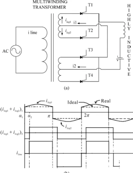
A multilevel converter circuit with RLE load works in two modes of operation i.e. rectification mode and in- verter mode. It works in inversion mode when the swit- ching angle of each of the converter is greater than 90˚. Here, a new multilevel circuit topology has been develo- ped as shown in Figure 1. The dc load side has been iso- lated from the grid via multi winding transformer.
The circuit has been analyzed and implemented for three level of line current and can be extended to higher levels for better performance. But the increase of level adds to the cost of converter and more number of secon- dary windings. So, a suitable compromise has to be made between the THD of the line current and cost of addi- tional hardware. When the circuit works in inverter mode, the dc source transfers power to the main (ac source). The major advantage of the proposed configuration is that in continuous current mode of operation, the waveform re- sembles a stepped sinusoidal wave and with suitable se- lection of switching angles the harmonic contents can be reduced drastically.
3. Control Strategy
In general, the load current can be either continuous or discontinuous. In the case of continuous current operation the current of both thyristors overlaps. It depends upon
(a)
(b)
Figure 1. Proposed multilevel converter circuit topology and its waveform. (a) Circuit (b) load current of each con-verter and input line current.
dc source voltage, phase angle of load or inductor (φ) and the switching angle.
1) Three level control strategy: For three level line cur- rent, a set of secondary winding with centre tap arran- gement is required. Each pair of thyristor in a centre tap secondary is fired at a switching delay of 180˚. The upper leg thyristor is fired at angle greater than 90˚ for inver- sion operation. Simultaneously lower leg thyristor is fired at a delay of 180˚ with respect to the upper leg thyrist or (see Figure 2).
The expression of the converter current is obtained by solving the equation
cos
m
di
L iR V t E
dt+ = ω + (1) For ωt = θ and
1 E m Vleg =
, it gives ileg1 for conduc-
tion through T1in positive half cycle in upper leg of con-
[image:2.595.312.534.86.374.2]For conduction through T2 in negative half cycle, the
expression of lower leg converter current is given by
(
)
( )
( ( ))(
)
( ( ) )1 tan 2
1 tan
cos 1
cos
cos
leg
m
i e
e
θ α π ϕ
θ α π ϕ
θ ϕ π
ϕ
ϕ α
− −
− − −
= − − − − ∗ −
+ − ∗
(3)
Each converter contributes to the line current and the net line current, iline, is equal to the sum of all (ileg1 +
ileg2)n. n = 1, 2.
4. Simulation Results
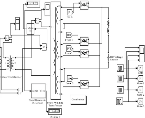
The three step inverter has been modeled in SIMULINK. The model is shown in Figure 3.
[image:3.595.70.284.115.177.2]The triggering pulses are given from the pulse genera- tor block of the simulink blockset. They are shown in
Figure 4. The value of inductor is 200 mH. Resistance is
[image:3.595.308.539.139.274.2]included to simulate the real inductor. The transformer ratio is 230V:40V. and 230V:50V:50V:50V:50V for multiwinding transformer. The simulation work is basi-
Figure 2. Waveform for three level line current with source voltage (Scale different).
Figure 3. SIMULINK model of the three step line commutated inverter.
[image:3.595.65.537.316.701.2]cally done to study the THD and average power variation of the line current with the firing angles. Line current with THD and harmonic is shown in Figure 5.
5.
Harmonics and Power Transfer Analysis
The THD and Power flow analysis is done for various configuration of switching angles. The effect of variation of dc voltage on the THD and the power transfer is also analyzed. Though a battery has been considered as a dc source for simulation as well as experimental analysis, the result obtained can be utilized when using solar PV panel. Since the dc voltage of a solar PV panel is not constant (vary with insolation, temperature and load), the effect of varying dc voltage on THD and power flow will help in developing a control strategy for operating the system in optimum condition i.e. changing the switching angle combination at different voltage level of PV panel. Variation of THD and power with switching angle com- bination for a three level inverter is shown in Figure 6
and Figure 7.
It is evident from Figure 6, the THD minima has been
achieved for triggering configuration as (α1 = 125˚, α2 =
140˚), (α1 = 120˚, α2 = 140˚), (α1 = 115˚, α2 = 145˚), (α1 =
110˚, α2 = 140˚).Global lowest being for (α1 = 125˚, α2 =
[image:4.595.309.538.147.329.2]140˚) i.e. 11.04%. It can be seen from Figure 7 that the power transfer increases respectively for the above con-
Figure 4. Triggering pulses from pulse generator.
[image:4.595.55.544.362.705.2]Figure 6. Variation of THD with switching angle combina- tion for a three level inverter.
Figure 7. Variation of Power with switching angle combina- tion for a three level inverter.
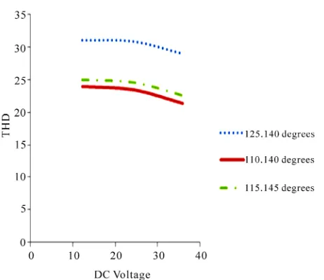
figurations. Thus, a suitable compromise has to be made between the two. For the above configurations, the varia- tion of THD and power with the dc voltage is studied and it is shown in Figure 8 and Figure 9.
The negative power transfer shows an increasing trend with the dc voltage whereas the THD is lower for smaller dc voltage.
6. Triggering Circuit
A UJT based triggering circuit has been designed to con-trol the switching angle. The angle is concon-trolled by chan- ging the resistance of the potentiometer. 1:1:1 pulse tran- sformer is used. The diode arrangement on the two secon-
Figure 8. Variation of power with selected switching com- bination.
Figure 9. Variation of THD with selected switching combi- nation.
dary winding is such that to obtain a phase delay of 180˚ between G1 and G2. The circuit diagram and the trigger-
ing circuit are shown in Figure 10 and Figure 11 respec- tively.
7. Results
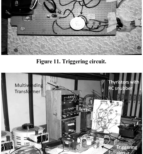
The complete experimental setup (prototype) is shown in
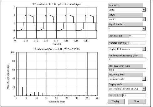
Figure 12. Multilevel transformer primary side is rated as 220 V. The secondary has two centre tap windings with voltage rating 50-0-50 each. The primary is fed via autotransformer. The autotransformer voltage is kept at 40V. Three level waveform and harmonics are shown in
Figure 10. Circuit diagram of the UJT based triggering circuit.
Figure 11. Triggering circuit.
[image:6.595.311.536.87.258.2]Figure 12. Complete set up of the multilevel grid tie inverter.
[image:6.595.311.535.284.461.2]Figure 13. Three level waveform.
Figure 14. Harmonics.
[image:6.595.59.287.386.562.2] [image:6.595.58.287.447.695.2] [image:6.595.311.539.489.688.2]Figure 16. Variation of THD with selected switching com- bination (Practical results).
for the switching angle combination (α1 = 110˚, α2 =
140˚). The THD in this case is 22.9%. Experimental re- sults are shown in Figure 15 and Figure 16. Graph has been plotted against power and THD with dc voltage for selected switching angle combinations. The experimental results are in accordance with the simulation results ob- tained in Figure 8 and Figure 9.
8. Conclusions
Multilevel inverter for three levels has successfully been implemented. A thorough study has been made to obtain optimal performance with battery as dc source and can be extended for solar PV modules. With reduced THD and features of multilevel inverter, it will to be a better re-
placement for square wave inverter in various distributed system connected to the grid.
REFERENCES
[1] J. Kumar, B. Das and A. Pramod, “Selective Harmonic Elimination Technique for a Multilevel Inverter,” Pro- ceedings of Fifteenth National Power Systems Confer- ence (NPSC), Bombay, December 2008, pp. 608-613.
[2] J. S. Lai and F. Z. Peng, “Multilevel Converters—A new Breed of Power Converters,” IEEE Transactions on Industry Applications, Vol. 32, No. 3, 1996, pp. 509-517.
[3] L. M. Tolbert, J. N. Chiasson, Z. Du and K. J. McKenzie, “Elimination of Harmonics in a Multilevel Converter with Nonequal DC Sources,” IEEE Transaction on Industry Applications, Vol. 41, No. 1, 2005, pp. 75-81.
[4] L. M. Tolbert, F. Z. Peng and T. G. Habetler, “Multilevel Converters for Large Electric Drives,” IEEE Transactions on Industry Applications, Vol. 35, No. 1, 1999, pp. 36-44.
[5] J. Iwaszkiewicz and B. J. Perz, “Multilevel Convertors for Distributed Power Generation Systems with DC Voltage Sources,” International Conference on Renewable Ener-gies and Power Quality, Saragossa, 2005.
[6] A. Myrzlk and M. A. Johanna, “Novel Inverter Topolo-gies for Single-Phase Stand-Alone or Grid Connected Photo-Voltaic Systems,” 4th IEEE International Confe-rence on Power Electronics and Drive Systems, Denpas-sar, October 2001, pp. 103-108.
[image:7.595.59.290.80.280.2]