Abstract—The geometry at the open end of the inlet tract and the effects of the transient phenomena due to the motion of piston and valves have a significant influence on tuning effects for optimum engine volumetric efficiency. Previous work at University of Leicester has been conducted into the effects of inlet tract radius on transient and steady flow properties that occur within the intake manifold using a general purpose CFD code, which are validated against the experimental data available. The optimum inlet tract radius along with the rest of the intake manifold geometry is consistent with the work reported here. In this project unsteady transient flow in a simplified computational model of a single cylinder and intake manifold of an internal combustion engine has been investigated, based on the successful application of dynamic mesh modeling techniques. The study mainly focuses on the effect of parameters such as bore of the cylinder (combustion chamber) and clearance length on the flow within both the intake manifold and the chamber itself. The work reported here will help build a set of optimum design parameters for achieving improved values of volumetric efficiency as well as highly efficient mixing of air and fuel in the combustion chamber.
Index Terms—CFD, IC engine, Pressure wave, Transient flow.
I. INTRODUCTION
The reciprocating internal combustion (IC) engine remains the first choice for a prime mover in today’s automotive industry. One of the more common varieties is the four-stroke spark ignition engine. To maximize the work output, one of the key requirements used in the design of an engine is the volumetric efficiency. This efficiency considers the ability of the engine to induce air (and fuel in some cases) into the combustion chamber. The significance of this is that the greater the quantity of air induced the more efficient the combustion will be. As a result of efficient combustion more power will be produced per cycle and less pollutant will be emitted into the atmosphere [1], [2].
Most research work on inlet manifold flow to date has been done either experimentally or via theoretical investigations using simplified models [3]-[7]. A review of these processes can be found from the work of Tabaczynski [8] and Winterbone et al. [9]. This project is a continuation of previous work at Leicester and the optimum operation conditions recommended by Blunt and Gao [10] are employed here. The commercial CFD package FLUENT is used to investigate how the initial clearance length and the
Manuscript received February 9, 2013; revised June 17, 2013.
The authors are with Department of Engineering, University of Leicester, Leicester LE1 7RH, UK (e-mail: [email protected]).
bore of the chamber affect the distribution of air within the chamber during the motion of the intake valve (i.e. during the induction and compression strokes). Details of the velocity and pressure distributions from four simulation models will be of interest along with the degree of turbulent kinetic energy that enters the chamber. All of these parameters are found to influence the flow characteristics in the combustion chamber, therefore, have an effect on the efficiency of the subsequent combustion.
It is well documented [2] that transient pressure waves initiated by the motion of the intake valve can increase the amount of air forced into the chamber. To see what effect changing the parameters mentioned above has on the time dependent phenomenon occurring in the intake manifold the time traces of instantaneous values of pressure and turbulence have also been analyzed in details. Furthermore computer animations of the pressure and velocity distributions in the intake manifold and the chamber have been carefully examined, which show effectively both the dynamic process of the complex flow and the ability of the CFD techniques to simulate the transient effects.
Nomenclature:
A surface area (m2)
BDC Bottom Dead Centre
L0 initial clearance length (mm)
R1 inlet pipe radius
R2/R1 expansion ratio
S source term
u
G
flow velocity vector (m/s)g
u
G
grid velocity of the moving mesh (m/s)V control volume (m3)
Greek Letters:
ρ fluid density (kg/m3)
Γ
diffusion coefficient Φ scalar quantitySubscripts: g grid
φ general scalar
II. COMPUTATIONAL MODELS
There are many parameters that affect the flow of air into the combustion chamber such as, the intake valve geometry, chamber size and shape, intake manifold geometry and tract open end characteristics. The key parameter used here is the optimum inlet tract radius of 10mm, reported initially by Blunt and Gao [10] and validated using an improved model
Computational Modeling and Analysis of Transient Flow
in an IC Engine with a Generic Inlet Tract
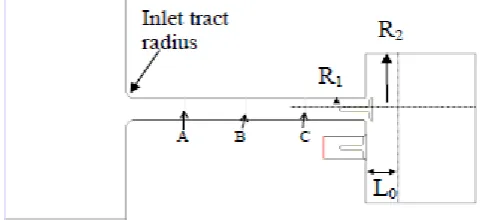
by Simpson [11]. This improved model has been further developed in this project, which includes a fully operational single cylinder with piston and valves moving in a typical four-stroke cycle. The geometry and dimensions of the plenum and intake manifold are taken from the work of Blunt and Gao [3] for continuity, as shown in Fig. 1 and Table I. Instantaneous velocity profiles are taken at three points along the intake manifold shown as A, B and C in Fig. 1.
Fig. 1. Schematic diagram of the simulation system
TABLEI:LEADING PARAMETERS OF THE SIMULATION MODELS Model
Number
Expansion ratio (R2/R1)
Initial clearance length (L0, mm)
Engine speed (rpm)
1 5.0 45 1500
2 2.5 45 1500
3 3.3 45 1500
4 3.3 9 1500
FLUENT operates on the principle of the finite volume method. During the solution process the computational domain is discretised into finite control volumes using a mesh specified by the user at the pre-processing stage. The CFD processor (FLUENT) uses the integral formulation of the conservation laws to calculate flow field quantities such as mass, momentum and energy within each cell of the computational mesh [12].
The model dimensions are adapted from a generic two-litre engine configuration supplied by Group Lotus plc to allow appropriate quantitative validation. The mesh and geometry are constructed in the pre-processor GAMBIT. The whole geometry is split up into different regions that can be meshed separately using different elements. Quadrilateral elements are used for the Tract Cell Zone. Triangular elements are used for the deforming Port and Chamber regions, with a combination of spring-based smoothing and local remeshing being used to update the grid after each time step. The Dynamic Layering update method [12] is employed for the regions above the valves and piston, this necessitates quadrilateral elements to be employed to allow appropriate addition and removal of cell layers to the moving boundary. As an illustration of the dynamic mesh method the integral form of the conservation equation for a general scalar, φ, on an arbitrary control volume, V, whose boundary is moving is given below:
∫
∫
∫
∫
∂ ∂ + ⋅ ∇ Γ = ⋅ − +V V V V
g dA dA SdV
u u dV dt d φ φ ρφ
ρφ (G G ) G G
(1)
Clearly, the effect of the grid velocity of the moving mesh has to be taken into considerations in the above equation.
The segregated solver is chosen for all the simulations, thus each conservation equation (for mass, momentum, energy etc.) is solved separately in sequential order [12]. The second order upwind interpolation scheme has been selected for the interpolation of parameters such as density, momentum and turbulent kinetic energy, as this scheme is recommended for geometries that use triangular mesh or have a high level of skewness. The PRESTO! (PREssure STaggering Option) discretisation scheme is employed due to its suitability for large pressure gradient and its provision for improved pressure interpolation in situations where large body forces or strong pressure variations are present. To avoid non-physical, checkerboard-type oscillations of the well-known pressure-velocity coupling the PISO scheme is preferred due to its ability to provide stable calculations for transient conditions with larger time steps, compared to the default SIMPLE algorithm. The PISO scheme uses a combination of the continuity and momentum equations to derive the equation for pressure [12]. The k-ε viscous model is used due to the turbulent nature of the flow around the valves and in the chamber, and its compatibility to the dynamic mesh scheme. Pressure conditions are applied to the inlet and outlet boundaries, with the static gauge pressure being set at 0 Pa.
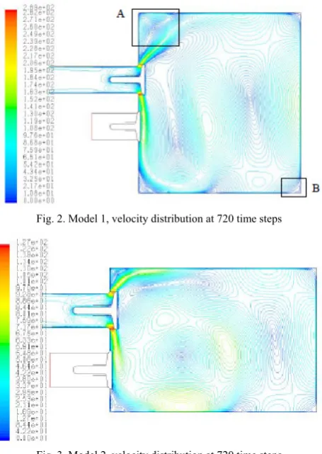
III. SIMULATION RESULTS AND DISCUSSION To ensure the reliability of the simulations, detailed code validations and grid independence tests have been conducted prior to the production simulations reported here [10], [11], [13], [14]. The simulation results from four models, as listed in Table I, are presented here for discussion. The first comparison is of two models with different expansion ratios (R2/R1 as shown in Fig. 1 and Table I). Fig. 2 shows higher velocities with model 1 (large expansion ratio) compared with model 2 (Fig. 3) within the chamber space. A possible reason for this is that there is a larger drop in pressure during the induction stroke for the large expansion ratio model due to the greater displaced volume. The extra volume also permits formation of extra vortices; in particular a vortex can be seen developing in the top left corner of the chamber (Fig. 2 and Fig. 4). In contrast the velocity contours for the small expansion ratio (Fig. 3) show that the flow from the intake valve interacts with the cylinder walls earlier on in the cycle and is drawn down the cylinder by the motion of the piston.
Fig. 2. Model 1, velocity distribution at 720 time steps
Fig. 3. Model 2, velocity distribution at 720 time steps
Fig. 4. Model 1, velocity vectors at 720 time steps showing the vortex at the top left corner, box A
Fig. 5. Model 1, velocity vectors at 480 time steps showing the vortex at the bottom right corner, box B
The dynamics of the system have been captured by recording instantaneous values of total pressure and turbulence at a cross section of 70 mm from the intake valve end of the inlet manifold. The plots of pressure and turbulence created using this data have shown that the
conditions within the model with a large expansion ratio are more favorable. This is in terms of the pressure variation as the intake valve closes (Fig. 6) and the level of turbulence recorded going into the combustion chamber (Fig. 7 and Fig. 8). The small expansion ratio model is found to produce lower pressure values (around -4000 Pa) at the examined cross section just before the valve closes compared to the large expansion ratio model with values around -2000 Pa (Fig. 6). This means that for model 2 more air escapes from the chamber back into the intake manifold as the valve closes, which could result in a lower volumetric efficiency in a real engine. From the instantaneous plots of turbulence of the flow entering the chamber (Fig. 7 and Fig. 8) it can be found that a higher peak value in turbulent kinetic energy is recorded during the simulation for the large expansion ratio model. The turbulent kinetic energy distribution in the chamber for model 1 is shown in Fig. 9 and the overall turbulence levels are indeed higher than those of model 2.
Fig. 6. Model 1, time history of instantaneous pressure
Fig. 7. Model 1, time history of turbulent kinetic energy
Fig. 9. Model 1, turbulent kinetic energy distribution at 720 time steps
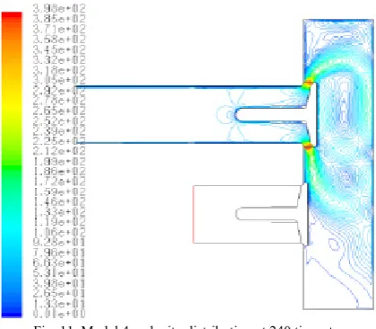
Fig. 10. Model 3, velocity distribution at 240 time steps
Fig. 11. Model 4, velocity distribution at 240 time steps
The second comparison is of models with different initial clearance lengths (Fig. 10 and Fig. 11). Results for the smaller clearance length model show enhanced chamber velocities (Fig. 11). This may be due to squish forces acting to direct the flow in the radial direction. With the small clearance length model the flow is greatly influenced by the motion of the piston resulting in relatively high velocities residing at the piston end of the cylinder at the end of the induction stroke.
Furthermore, an analysis of the animation of total pressure for model 1 shows clearly the creation and evolution of vortices in the combustion chamber due to the motion of piston and valves. To allow analysis of the dynamics within the intake manifold during induction the individual plots that
make up the animation are studied in isolation. As the valve opens the contours show a pressure distribution indicative of movement to the open end of the manifold for a short period (approx. 0.003 seconds, or 100 time steps). This is followed by the main influence of the piston, which lowers the pressure in the chamber relative to the open end and draws air into the chamber. This continues up until 0.015 seconds (or 500 time steps) at which point the intake valve is starting to close and the pressure differential changes from a pressure gradient drawing air into the chamber to one that sends a wave upstream. The change in pressure conditions may be due to the closing of the valve that retards the flow attempting to pass the intake valve. The wave that is sent upstream, to the open end of the manifold, acts to reduce the velocity in the manifold [1], [2].
A change in direction of the flow is observed at 0.023 seconds (or 830 time steps) into the simulation, 0.004 seconds before the intake valve is completely closed at 0.027 seconds. This change in direction may be caused by the reflection of the first pressure wave at the inlet tract radius increasing the flow into the cylinder just as the intake valve is closing. The changes in velocity magnitude are also analyzed in details and two examples of the velocity profiles are compared at 480 and 720 time steps, which show clearly the velocity magnitudes decrease at 720 time steps due to the valve closure effect. All these results will be presented at the conference.
IV. CONCLUSION
All the CFD simulations reported in this paper have been carried out using the software package GAMBIT and FLUENT. The computational models have been carefully constructed and meshed using GAMBIT, and then subsequently analyzed by the FLUENT solver. Apart from the detailed analysis of velocity and pressure profiles, contours and vectors at selected time and positions, dynamic flow animations have been used to study the transient pressure wave and the creation and evolution of vortices in the combustion chamber due to the motion of piston and valves.
From the results presented here an optimum model of a combustion chamber of an internal combustion engine operating at 1500 rpm would have a large expansion ratio (i.e. larger cylinder bore) and a small clearance length. This combination would allow vortices to develop unhindered by the cylinder walls while at the same time providing a small clearance for squish to occur and turbulence to be maintained. Careful analysis of the pressure animation has allowed the explanation of the dynamics of the intake manifold during the motion of the intake valve. This demonstrates that CFD techniques are useful predictive tools for studying the dynamics of complex transient flow.
REFERENCES
[1] R. Stone, Introduction to Internal Combustion Engines, 2nd ed. Macmillan, 1985.
[3] H. W. Engleman, “Design of a tuned intake manifold,” ASME Paper, 1973.
[4] P. C. Vorum, “Short pipe manifold design for four-stroke engines,” J.
Eng. Gas Turbines Power,vol. 102, no. 4, pp.836-841, 1979.
[5] G. Cser, “Some results of combining charging systems,” in Proc. of the
ImechE, 1978.
[6] M. C. Brands, “Helmholtz tuned induction system for turbocharged diesel engine,” SAE Technical Paper 790069, 1979.
[7] S. Yagi, A. Ishizuga, and I. Fujii, “Research and development of high speed, high performance small displacement honda engines,” SAE Technical Paper 700122, 1970.
[8] R. J. Tabaczynski, “Effects of inlet and exhaust system design on engine performance,” SAE Technical Paper 821577, 1982
[9] D. E. Winterbone, D. Worth, and J. R. Nichols, “A comparison of synthesis and analysis models for wave action manifolds,” in Proc. of
ImechE, 1989.
[10] P. Blunt and S. Gao, “CFD analysis of inlet manifold tuning and entry radius effects on a four-stroke internal combustion engine,” in Proc.
11th ACME Conference, Glasgow, 2003.
[11] R. Simpson, “CFD Analysis of a piston-driven transient flow in an IC engine,” Leicester University Report, 2004.
[12] Fluent Inc, FLUENT Manuals, 2003.
[13] K. C. Lee, K. O. Suen, M. Yianneskis, and G. Ganti, “A comparison of CFD prediction and LDA measurements of the flow through a generic inlet port,” in Proc. 2nd Biennial European Joint Conference, vol. 8, pp. 85-94, 1994.
[14] A. White and M. A. Passmore, “Measurement of air flow around an inlet valve using a pitot probe,”SAE Technical Paper 980142, 1998.
R. Simpson had his MEng from the Engineering Department of Leicester University in 2005. His main research interests are in CFD, IC engine flow, aerodynamics, turbulent flow and heat transfer.