382
All Rights Reserved © 2013 IJARCSEE
1-D DCT Using Latency Efficient Floating Point
Algorithms
Viswanath Gowd A, Yedukondala Rao V,
T. Shanmuganantham
Abstract— This paper presents the design of one-dimensional
discrete cosine transform (DCT) architecture for digital signal processing (DSP) applications. DCT is a basic transformation for coding method which converts spatial domain to frequency domain of image. In 1-D DCT operation addition, subtraction, multiplication operations are required. These operations must be accurate, less latency. Floating point operations have dynamic range of representation, more accurate and perform millions of calculations per second. So the floating point operations are used for the above operations. In this floating point adder/subtractor is the most complex operation in a floating-point arithmetic and consists of many variable latency- and area dependent sub-operations. In floating-point addition implementations, latency is the primary performance bottleneck. So different types of floating point adder/subtractor algorithms such as LOD, LOP, Two-path are used to decrease the latency. The trade off is observed in 1-D DCT by changing different types of adders in place of summer. All architectures are designed and implemented using VHDL using Xillinx 13.1software.
Keywords:-DCT, Floating point operations, FPGA
I. INTRODUCTION
Discrete Cosine Transform (DCT) is a mathematical tool that has a lot of electronics applications, from audio filters to IMAGE compression. Image compression is the science of efficiently coding digital images to reduce the number of bits required in representing an image. Recent advances in digital technology have led to communication media in which visual information plays the key role.
Manuscript received April, 2013.
Viswanath Gowd A, Department of Electronics Engineering, Pondicherry University, Pondicherry, India, Mobile No.,09786539150
Yedukondala Rao V, Department of Electronics Engineering, Pondicherry University, Pondicherry, India, Mobile No.,09966228330
T. Shanmuganantham, Department of Electronics Engineering, Pondicherry University, Pondicherry, India, Mobile No.,09486640168
Some of the emerging applications include high definition TV, videoconferencing, video telephony, medical imaging, virtual reality, video wireless transmission and video server.DCT transforms the information from the time or space domains to the frequency domain, such that other tools and transmission media can be run or used more efficiently to reach application goals: compact representation, fast transmission, memory savings, and so on.DCT, first proposed by Ahmed [4] et al, 1974, has got more importance in recent years, especially in the fields of Image Compression and Video Compression. This PAPER focuses on efficient hardware implementation of floating point operations in DCT by decreasing the number of computations, enhancing the speed of operation. As a result of which the area consumption increases. The Discrete Cosine Transform of a one dimensional sequence of length N is defined as
F(u) = α(u) Σ f(x) cos [pi(2x+1)u/2N];
for u=0,1,2…N-1 (1)
The Inverse DCT transformation is defined as
f(x) = Σ α(u) c(u) cos[pi(2x+1)u/2N];
for x=0,1,2…N-1 (2)
In both the equations above α(u) is defined as
α(u)= sqrt(1/N) for u=0 sqrt(2/N) for u≠0
For more than N sample points the entire sequence can be divided into sequences of length N and then DCT can be independently applied to these smaller blocks.
383
All Rights Reserved © 2013 IJARCSEE
This paper focuses only on normalized binary interchange format. The representation consists of a one bit sign (S), a seven bit exponent (E), and a ten bit fraction (M or Mantissa). An extra bit is added to the fraction to form what is called the significand. Floating point value
(v) = -1s × 2(e-63) (1.f)
II. 1-D DCT ARCHITECTURE
The architecture of 1-D DCT is implemented from the butterfly as shown in Figure 1. This architecture consist of eight 18-bit register, two 18-bit multiplexers (8x1), one 18-bit multiplexer (2x1), one floating point adder (18-bit), one floating point subtractor (18-bit), one floating point multiplier (18-bit), six 18-bit latch and a controller. The design considerations made in this architecture are: Exploiting parallelism, pipelining and reusability concept is incorporated so that area minimization can be achieved considerably. The sequence of operation carried over in this architecture are: Initially the 8 inputs [x (0), x (1)………..x (7)] i.e., the pixel image values are serially loaded into eight 18-bit registers. All the outputs of registers are given to the multiplexer1 and multiplexer2. The register values are selected depending upon the control that is given by the controller. The controller is designed using a Finite State Machine (FSM) to control the overall operation of the architecture.
Therefore the value in one register is selected by the multiplexer at a time. The outputs of multiplexer1 and multipexer2 are latched at latch1 and latch2. Correspondingly the values from latch1 and latch2 are given to adder and subtractor module. The output of adder and subtractor are stored in latch3 and latch4. The cosine values are stored using lookup table and the controller provides the necessary cosine terms to the multiplier using latch5. Finally the outputs of adder and multiplier are stored in the selected registers depending upon the selection of multiplexer3. The controller architecture is designed using Finite State Machine (FSM). The total number of states required to complete this 1-D DCT will be 200. The controller uses clk, reset, start, addflag, subflag and mulflag signals as its input. The enables of registers, the enables of mux1, mux2, mux3, adder, subtractor, lut, multiplier, sel1, sel2, addr_lut are outputs of this controller.
Fig 1 Architecture of 1-D DCT [1]
III. FLOATING POINT ARCHITECTURES
A. Floating Point Addition/Subtraction
In floating point addition (or subtraction), the two numbers must have equal exponents for their mantissas to be added (or subtracted) correctly. For addition and subtraction, it is necessary to ensure that both operands have the same exponent value. This may require shifting the radix point on one of the operands to achieve alignment. Multiplication and division are straighter forward. Problems may arise as the result of these operations:
Exponent overflow: A positive exponent exceeds the maximum possible exponent value. In some systems, this may be designated as +∞ or - ∞.
Exponent underflow: A negative exponent is less than the minimum possible exponent value (e.g., - 16 is less than - 14).This means that the number is too small to be represented, and it may be reported as 0.
Significant underflow: In the process of aligning significant, digits may flow off the right end of the significant.
384
All Rights Reserved © 2013 IJARCSEE
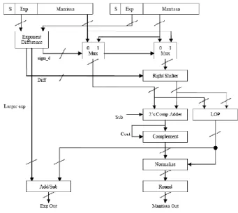
B. LOD Floating Point Adder/Subtractor Unit
The steps in floating point adder LOD algorithm is as follows:
1. Exponent subtraction: Subtract the exponents and denote the difference d=E1-E2.
2. Pre alignment: Right shift the significand of the smaller operand by d bits. Denote the larger exponent Elarge .
3. Adder/sub: Perform addition or subtraction according to the effective operation, Eo, which is the arithmetic operation actually carried out by the adder in the FP unit.
4. Conversion: Convert the result to sign-magnitude representation if the result is negative. The conversion is done with an addition step.
5. Leading one detection (LOD): Compute the amount of left or right shift needed and denote it En. En is positive for a right shift and negative otherwise.
6. Normalization: Normalize the significand by shifting En bits and add En to Elarge .
7. Rounding: Perform IEEE rounding by adding „1‟ when necessary to the LSB of output result . This step may cause an overflow, requiring a right shift. The exponent, Ef , in this case has to be incremented by 1.
Fig 2 LOD algorithm
C. LOP algorithm
In this section, LOP implementation and its use in floating-point addition is described in detail. LOP module is also used in far and close data-path algorithm implementation. LOP is used to predict the leading one in parallel with the adder computation. This decreases the number of logic levels in the
critical path and results in an overall improvement in the latency.
The LOP consists of two operations:
• Pre-encoding the inputs • Leading one detection
Fig 3 LOP algorithm.
Parallel, leading one detection and correction adds area to the design but decreases the overall latency of the module by reducing levels of logic. A and B are the two inputs, the leading one predictor designed is for A > B and/or A <B. This is needed because even after pre-normalization, the resulting addition can be negative as in case of A < B. When the effective operation is addition, the LOP result is not used and the shift value is always zero
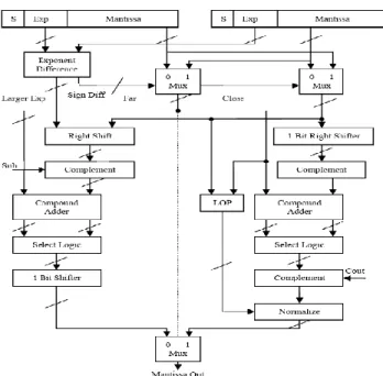
D. FAR AND CLOSE path algorithm
385
All Rights Reserved © 2013 IJARCSEE
leading number of zeros only when the effective operation is subtraction and the exponent difference is 0 or 1, for all the other cases no leading zero count is needed. the micro-architecture of the far and close path floating point adder is shown in figure 4. The exponent difference and swap units for pre-normalization are the same as in the standard or LOP algorithm. The two fractions, exponent difference, and larger exponent are the common inputs to both the paths. Close path is chosen if the exponent difference is 0 or 1 and the effective operation is a subtraction otherwise the far path is chosen. The close and far path will be explained in detail as below.
. Fig 4 far and close datapath algorithm.
E. Floating point multiplier
A multiplication of two floating-point numbers is done in four steps:
1. Non-signed multiplication of mantissas: it must take account of the integer part, implicit in normalization. The number of bits of the result is twice the size of the operands (48 bits)
2. Normalization of the result: the exponent can be modified accordingly
3. Addition of the exponents, taking into account the bias
4. Calculation of the sign
Fig 5 Floating-point multiplier.
IV. SIMULATION RESULTS AND DISCUSSION
A. Floating point adder/subtracton
The opa and opb are the two inputs of floating point adder and add is the output of floating point adder. The overflow bit will be high if range exceeds the maximum value and underflow bit will be high if range is smaller than minimum value
Fig 6 Behavioral simulation of FP adder/subtractor
B. Floating point multiplier
386
All Rights Reserved © 2013 IJARCSEE
Fig 7 Behavioral simulation of FP multiplier
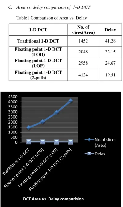
C. Area vs. delay comparison of 1-D DCT
Table1 Comparison of Area vs. Delay
Fig 7 Graphical Representation of Area vs. Delay Comparison
V. CONCLUSION
This paper describes the efficient use of VHDL code for the implementation of 1-D DCT architecture and the simulation results of the various stages has been obtained successfully. The tradeoff between area and delay is obtained by using different types of floating point adder (LOD, LOP, Far-Close path) algorithms in place of ADDER in architecture.
VI. FUTURE SCOPE
The future scopes of this project are to implement the proposed 1-D DCT architecture using Field-Programmable Gate Arrays (FPGAs).
REFERENCES
[1] R.Uma “FPGA Implementation of 2-D DCT for JPEG Image Compression”, International journal of advanced engineering sciences and technologies, 2011, Vol No. 7, Issue No. 1, pp.001 – 009.
[2] A. Kassem, M. Hamad, E. Haidamous, “Image Compression on FPGA using DCT," International Conference on Advances in Computational Tools for Engineering Applications, 2009, ACTEA '09, pp.320-323, 15-17 July 2009.
[3] N. Shirazi, A. Walters, and P. Athanas, “Quantitative Analysis of Floating Point Arithmetic on FPGA Based Custom Computing Machines,” Proceedings of the IEEE Symposium on FPGAs for Custom Computing Machines (FCCM’95), pp.155–162, 1995.
[4] Ahmed,H.M.,Delosme, J.M.,and Morf,M.,"Highly Concurrent Computing Structure for Matrix Arithmetic and Signal Processing", IEEE Comput. Mag, Vol.15, 1982, pp.65-82.
[5] B.G. Lee, ”A new algoritm to compute the discrete cosine transform”,IEEE Trans. Acoust., Speech, Signal Processing, vol. ASSP-32, pp. 1243-1245, Dect.1984.
[6] H.S Hou, “A fast recursive algorithms for computing the discrete cosine transform”, IEEE Trans. Acoust., Speech, Signal Processing, vol. ASSP-35, pp. 1455-1461, Oct.1987.
[7] N.I Cho and S.U.Lee, “DCT algorithms for VLSI parallel implementation”, IEEE Trans. Acoust., Speech, Signal Processing, vol 38. pp. 121-127, Jan.1990.
[8] N. Ahmed, T.Natarajan, and K.R. Rao, “Discrete Cosine Transform”. IEEE Trans. Commun., vol, COM-23, pp. 90-93, Jan. 1974.
[9] Nabeel Shirazi, Al Walters, and Peter Athanas “Quantitative Analysis of Floating Point Arithmetic on FPGA Based Custom Computing Machines‖ presented”, IEEE Symposium on FPGAs for Custom Machines, Napa Valley, California, April 1995.
[10] M. Vetterli, “Fast 2-D Discrete Cosine Transform”,‖in Proc. ICASSP‘85. Mar.1985.
[11] Jongsun Park Kaushik Roy A Low Complexity Reconfigurable DCT Architecture to Trade off Image Quality for Power Consumption Received:2 April 2007 / Revised: 16 January 2008 / Accepted: 30 April 2008 /Published online: 3 June 2008.
0 500 1000 1500 2000 2500 3000 3500 4000 4500
DCT Area vs. Delay comparision
No.of slices (Area)
Delay
1-D DCT No. of
slices(Area) Delay Traditional 1-D DCT 1452 41.28
Floating point 1-D DCT
(LOD) 2048 32.15 Floating point 1-D DCT
(LOP) 2958 24.67 Floating point 1-D DCT
387
All Rights Reserved © 2013 IJARCSEE
[12] Jin-Maun Ho, Ching Ming Man, ―The Design and Test of Peripheral Circuits of Image Sensor for a Digital Camera,‖ IEEE International Conference on Industrial Technology, 2004. IEEE ICIT '04, vol.3, pp.1351 – 1356, 8-10 Dec. 2004.
[13] Junqing Chen, Kartik Venkataraman, Dmitry Bakin, Brian Rodricks, Robert Gravelle, Pravin Rao, Yongshen Ni, “Digital Camera Imaging System Simulation”, IEEE Transactions on Electron Devices,vol.56(11), pp.2496 – 2505, Nov. 2009.
Viswanath Gowd Akkili obtained his B.Tech degree (2009) in Electronica & Communication Engineering from St. JOHN'S COLLEGE OF ENGG. & TECH., (Affiliated to JNTU, ANANTHAPUR). Currently, he is studying M.Tech in the Dept. of Electronics Engineering, School of Engineering and Technology, Pondicherry University, Pondicherry, India.
Yedukondala Rao Veeranki obtained his B.Tech degree (2010) in Electronica & Communication Engineering from BAPATLA ENGINEERING COLEEGE(AUTONOMOUS), BAPATLA. Currently, he is studying M.Tech in the Dept. of Electronics Engineering, School of Engineering and Technology, Pondicherry University, Pondicherry, India.
![Fig 1 Architecture of 1-D DCT [1]](https://thumb-us.123doks.com/thumbv2/123dok_us/8091524.2144083/2.918.490.864.156.442/fig-architecture-of-d-dct.webp)