© 2017 IJSRST | Volume 3 | Issue 1 | Print ISSN: 2395-6011 | Online ISSN: 2395-602X Themed Section: Science and Technology
Comparative Study of Affecting Parameters on Modulus of FRP
Prof. P. V. Savalia
Department of Mechanical Engineering, Government Engineering College, Bhuj, Gujarat, India
ABSTRACT
In a present era importance of FRP are steadily increasing due to its advantageous properties Various researchers have worked for high strength fiber reinforces plastic as an attractive feasible material to replace metal and conventional materials. Normally the rule of mixture can give reasonable results for predicting the end properties of FRP in longitudinal direction. However, for different fiber arrangement and length of fiber the loss in modulus is expected. Further, interfacial de-bonding, poor adhesion and voids also create loss in modulus of FRP. Hence, this research paper is aimed to found the losses in modulus of FRP by considering natural fiber jute as a reinforcement and polyester as a matrix. The systematic experiments are carried out by using suitable molds and appropriate equipment. The attempts are made to study the effect of volume fraction of fiber on modulus for continuous long fibers and randomly distributed short fibers also effect of fiber breakage, fiber length and fiber orientation is studied for modulus under longitudinal loading. The attempt is also made to study effect of volume fraction of fiber on modulus for fibers subjected to transverse loading. Finally, modulus property is simulated using standard FEA packages. The results obtained by 3D FEA analysis, theoretical models and experimental results for losses in modulus are following the same trend. The comparative assessment give the divergence of experimental results from available predictive model in term of modulus losses is the range of (0.16-75.06) % depending on various parameters.
Keywords : Longitudinal, Transverse, Modulus, FRP, FEA, ANSYS, I-DEAS, RVE.
I.
INTRODUCTION
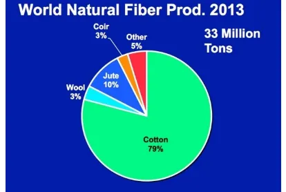
Ecological concerns have resulted in renewed interest in natural materials. Development of natural fibers reinforced composites is highly attractive research lines and production of natural fiber in worldwide as shown in Figure 1. A natural fiber provides interesting properties for composites, especially capacity of recycling, renewable raw material, which is less abrasive and harmful to mankind.
A composite is defined as a multiphase material and composition of material differing in composition, which remain bonded together, but retain their identities and properties, without going to any chemical reaction. Composite is engineered to meet specific application, performance and specific needs.
The importance of Polymers, Composites and Ceramic based composites is steadily increased in a present era [1].
Figure 1. Worldwide production rate of Natural fiber
II.
METHODS AND MATERIAL
Reinforcement of Natural Fibers
to be feasible reinforcement materials. Numerous attempts are already made to study properties of jute and other natural fiber in combination with thermosetting and thermoplastics in a last two decades. [3]
Losses in Property of Frp Materials
Generally the rule of mixture gives reasonable results for predicting the end properties of FRP in longitudinal direction. However, experimental condition may affects the loss of modulus will be inevitable [4, 5, 6, 7]. Further, the concept of poor adhesion, interfacial de-bonding and voids also creates loss in modulus of composite [8]. The interfacial bonding influences the tensile modulus through mechanics of ineffective length and broken fiber [5]. The orientation of fiber is very important factor in reduction of modulus of composites as the fiber contains high anisotropic in their nature [4, 9, 10].
Hence, this research work is aimed to find the losses in modulus of fiber reinforced plastic. The systematic experiments are carried out by using suitable molds and strength testing equipment. The attempts are made to comparative study the effect of volume fraction of fiber on modulus for continuous long fibers subjected to (1) longitudinal loading and (2) transverse loading.
Finally, the loss in modulus is also simulated by finite element analysis using standard FEA package like IDEAS and ANSYS is carried out. The comparative study of the results obtained by 3D FEM analysis and theoretical models and experimental results are used for analysis of loss in modulus.
MICROMECHANICS MODELS
The simplest form of reinforcement widely used in practice is the use of unidirectional long fibers to fabricate composite material in matrix media. To determine modulus, strength etc using the properties and arrangements of constituent fibers and matrix material micro mechanic analysis is used while; macro mechanic analysis provides analytical solution for thick Composite made by number of plies, where individual ply may have individual characteristics, arrangements which are governed by micro mechanic model. Considering isotropic reinforcement in isotropic matrix media,
modulus, strength, Poisson’s ratio etc of composite material are predicted along longitudinal directions using simple rule of mixture. The basic assumptions in deriving it are as below:
1. Fibers remain parallel and that the dimensions do not change along the length of the element.
2. Perfect bonding at interface (no slip occurs between fiber and composite).
3. Fiber and matrix materials are linearly elastic and homogeneous.
4. Matrix is isotropic. 5. Fiber as an anisotropic.
Variety of predictive models in the literature which are either derived theoretically based on parametric constraints or semi empirically based on experimental studies. Few of such predictive models are available in the literature along with the models incorporating effect of various constituent parameters.
Effect of fiber content on longitudinal modulus of FRP
J. M. Whitney [4] static equilibrium requires that the total resultant force on the element must equal to the sum of forces acting on the fiber and matrix. Combining the static equilibrium condition leads to formation of Rule of mixture equation 1.
c f f m m
E = E v +E v …………Equation 1
Puck also proposes the model based on the concept of approximation considering the properties of longitudinal equation 2.
c m f
E = E (3.92v +0.89)…...Equation 2
Effect of fiber content on transverse modulus of FRP
4 4 2 2
ll ll ll
12 θ
E E E
= cos θ + sin θ + - 2μ cos θsin θ
E E G Equation 3
On the same bases the model proposed by Horio [13] is shown as equation 4, composite material.
ll
θ 2 2
ll
E E E =
E sin θ +E cos θ …………Equation 4
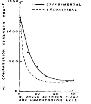
Abu-Farsakh, [14] describes the modes of failure of fibrous composite material as affected by the orientation angle of fiber using transformation equations of principal material direction.
Figure 2. Effect of orientation angle on composite strength
The interphase becomes critically design variable in case of transverse reinforcement. Transverse loading focuses failure region mainly at interphase and it is reducing gradient between fiber and matrix even less than the matrix. The simplest tool for predicting transverse modulus is inverse rule of mixture as shown in equation 5 , but it is derived based on the assumption of equal stress in fiber and matrix which may not be the true case in practice hence it can only be utilised as approximate primary tool. Whitney [4] uses the transverse properties in rule of mixture and observed better convergence in the result as shown in Figure 3 which is given as equation 6. Nielson proposes model of transverse by equation 7.
f m
T f m
1 v v
= +
E E E ……….Equation 5
T f2 f m m
E =E v +E v
……….Equation 6Figure 3. Transverse modulus is a function of fiber volume for anisotropic & isotropic filament Composite
Fig. 2. (a) Transverse modulus is a function of fiber volume for anisotropic & isotropic filament Composite.
f m m m f m m
f f m m
m m f m m
M 2M +G - G M -M v E = 2 1-μ + μ -μ v
2M +G + 2 M -M v
…….Equation 7
Where,
m
m
m E M =
2 1-μ
f
f
f E M =
2 1-μ
Manera [10] referred the approximate equation 8 proposed by puck
2 m f c 2 1.25m m f
f 2
f m
E 1+0.85v
E = (
1-μ 1- v +E v E 1- v
)
…….Equation 8
OBJECTIVE OF RESEARCH
Study of literature indicates that there exists variety of models based on individual parameters to predict the end properties of fiber reinforced plastics and they all exhibits the concept of losses in end properties. The attempts made for jute and other natural fibers, of course provides data but their behaviour characteristics with respect to various affecting parameters still requires detailed systematic study. Hence the need is felt to carry out systematic experiments for in depth study. As the jute is easily available stiff fiber, which is also exhibits interface uncertainty. Hence jute and general purpose polyester resin is used to carry out experiments. Also,
the effect of matrix contribution, interfacial parameters and voids are not studied extensively in the literature. The lack of sufficient experimental data in the literature gives clear indication regarding requirement of an in-depth study to carry out detailed experimental & analytical investigations to find parametric losses in end properties and to correlate them in generalized manner.
Based on the conclusions derived from the literature the objectives of present work are:
1. To develop a mold and press set up for preparing specimens using jute as reinforcement and polyester resin as a matrix material.
2. To study the effect of fiber content on Modulus of jute composite for longitudinal loading.
3. To study the effect of Fiber content on Modulus of jute composite for transverse loading.
4. To simulate modulus losses of jute reinforced plastics by FEA through standard FEA package like IDEAS and ANSYS and to carry out comparative study of these results with experimental results and to analyse the losses in Modulus.
MOLD AND SPECIMEN PREPARATION
The mold is developed for experimentation during the course of this work. It primarily consists of bottom plate attached with detachable pieces to form a rectangular cavity. The arrangement is done in such a way that five specimens can be prepared at a time at a uniform pressure. The top plate of mold is fixed with individual punches to form punch plate assembly. Entire mold is prepared from wooden material glued with 1 mm thin Formica sheet at contact surfaces. The intension of using Formica is to provide smooth surface. The oil is also used at matting surface to avoid sticking of specimen with cavity or with the punch after solidification. The schematic diagram of mold is shown in Figure 4.
Figure 4. Mold set up
EXPERIMENTAL DETERMINATION OF MODULUS
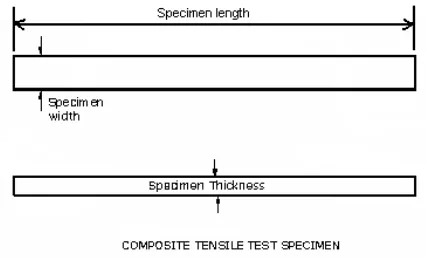
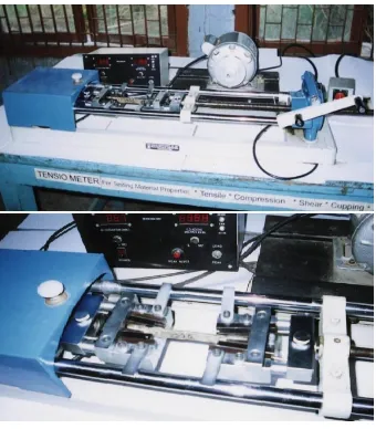
The prepared specimens in mold as shown in Figure 5 are initially tested the tensile strength on UTM (make: AMILI Co. Ltd., London) of capacity 20 ton, with minimum accuracy of 5 kg and finally testing was carried out on Tensiometer (make Mikrotech, manufactured by Kudale Enterprise, Pune.) is used for measuring the breaking load capacity is within 2 tons, with minimum accuracy of 1 kg and displacement with least count of 0.1 mm. Strength measuring set up is shown in Figure 6. The length of specimen before test and after test was measured by digital vernier caliper of least count 0.01mm. During the test, wedge type grippers are used for flat specimen with rectangular cross section.
Figure 5. Tensile test specimen
The load is applied to obtain breaking of specimen and the Modulus of composite is obtained by using equation as follows
Where,
σ = stress (Kg/cm2) σ = P/A
ε = strain ε =dl/L
P=Breaking load (Kg)
A= Cross sectional area of specimen (cm2)
dl= Change in Length of specimen (Final length – Initial length)(mm)
L= Initial length (mm)
Figure 6. Strength measuring equipment Tensiometer
EXPERIMENTAL METHODOLOGY
The experimental investigations are carried out in six different phases as described below:
Long continuous fibers
The effect of fiber content is investigated by maintaining 0° of fibers with loading direction in case of long continuous fibers. The fibers are taken in bunch with different weight so as to get variation in volume fraction [4 to 38%] and constant quantity of resin is poured. The Modulus of each specimen is measured and the effects of fiber content for long continuous fibers have been investigated. Specimens of longitudinally aligned fiber composite are shown in Figure 7.
Transversely placed fibers
The effect of fiber content is studied keeping the fiber angles at 90° with respect to loading direction. The fiber
content is varied from 15% to 40 % and its effect on Modulus of the composite is measured. Specimens of transversally aligned fiber composite are shown in Figure 7.
Figure 7. Specimens of Fiber Reinforced Polyester
ANALYTICAL STUDY
The aim to observe the simulated results obtained by standard FEA packages IDEAS and ANSYS. The jute reinforced plastic is represented as a represented volume element in the form two concentric cylinders, where concentric cylinder represents reinforcement and outer cylinder represents matrix material. The condition of perfect joining at interface is maintained in both the FEA packages without considering any other interfacial effects.
SIMULATION OF MODULUS BY FEA PACKAGES
Three dimensional representative volume elements are modeled in FEA packages. In both the FEA packages the necessary boundary conditions are applied. All degree of freedom is restricted at back face and front face of fiber and matrix is allowed to undergo displacement for a experimental strain value in longitudinal direction. The property of fiber and matrix is assigned to respective part of representative volume element. The meshing is carried out by solid tetrahedron element.
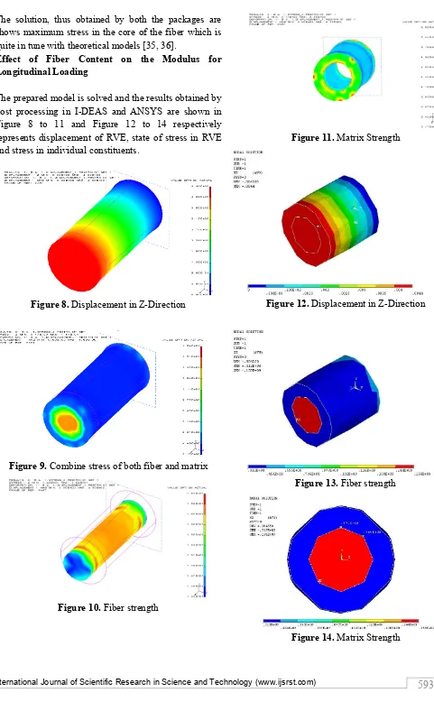
The solution, thus obtained by both the packages are shows maximum stress in the core of the fiber which is quite in tune with theoretical models [35, 36].
Effect of Fiber Content on the Modulus for Longitudinal Loading
The prepared model is solved and the results obtained by post processing in I-DEAS and ANSYS are shown in Figure 8 to 11 and Figure 12 to 14 respectively represents displacement of RVE, state of stress in RVE and stress in individual constituents.
Figure 8. Displacement in Z-Direction
Figure 9. Combine stress of both fiber and matrix
Figure 10. Fiber strength
Figure 11. Matrix Strength
Figure 12. Displacement in Z-Direction
Figure 13. Fiber strength
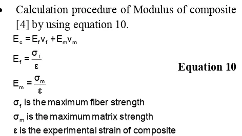
Calculation procedure of Modulus of composite [4] by using equation 10.
c f f m m
f f
m m
f m
E = E v +E v σ
E = ε σ E =
ε
σ is the maximum fiber strength σ is the maximum matrix strength ε is the experimental strain of composite
Equation 10
Effect of Fiber Content on Modulus for Transverse Loading
The model is built at 90o to X-axis in order to give transverse loading condition as the fiber is considered as anisotropic material as shown in Figure 15 Again the binding conditionand circle dimension.
Figure 15. Volume of Composite
The boundary condition and meshing is also implied in similar manner. However the assigning of constituents properties requires little alteration to consider anisotropy in fiber. The major properties of fiber is along X direction and hence it is loaded in Z direction. The anisotropic property of fiber is used as 6×6 matrix which is calculated using mathcad as shown below.
The model is solved and results obtained for displacement, state of stress in RVE and stresses in constituents are shown in Figure 16 to 19 for I-DEAS and Figure 20 to 22 for ANSYS.
Figure 16. Displacement in Z-Direction
Figure 17. Combine stress of both fiber and matrix
Figure 18. Fiber Strength
Figure 20. Displacement in Z-Direction
Figure 21. Fiber strength
Figure 22. Matrix strength
III.
RESULTS AND DISCUSSION
The experimental results obtained for parameters volume fraction attempted on long continuous fibers and transversely placed fibers are attempted during research work are described below
Effect of Fiber Content on the Modulus for Longitudinal Loading\
1. Figure 23 and Figure 24 shows the comparative results of theoretical Models and FEA packages simulated results of Modulus respectively as a function of vf for the long continuous fiber with experimental results. It is worth to mention that theoretical and packages predictions are on higher side as compared to experimental results. This may be attributed to the presence of voids, ineffective contribution from matrix and fiber other interfacial effects [5], while in theoretical models it is assumed that there is perfect bonding between fiber & matrix and absence voids. Again in FEA package the glue option is used to maintain perfect bonding and voids are not considered during the modeling.
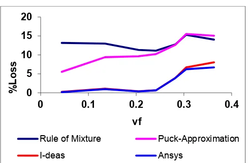
2. Figure 25 shows the loss in Modulus as a function of vf for the long continuous fiber. The comparison clearly indicates rise in divergence as vf increase. The divergence of model ROM & Puck is highest and the losses observed (12.2-13.5)% & (l5.5-15.4)% as they are independent of strain value. While the divergence is reduced as (0.2-8)% & (0.16-6.68)% in case of I-DEAS and ANSYS as their simulated value are depending on experimental strain value and not only on constituents property. However trend is very much in line with above referred models.
Figure 23. Comparative results for modulus predicted by theoretical models with experimental results
considering long continuous fibers 0
10000 20000 30000 40000 50000 60000
0 0.1 0.2 0.3 0.4
M
o
d
u
lus
(kg/cm
2)
vf
Experimental Rule of mixture
Figure 24. Comparative results simulated by FEA packages with experimental results for long continuous
fiber composite
Figure 25. Comparative results of losses in modulus on long continuous fiber composite
Effect of Fiber Content on Modulus for Transverse Loading
1. Figure 26 and Figure 27 shows the comparative results of theoretical Models, Package simulated values of Modulus respectively as a function of vf for the continuous fiber composite subjected to transverse loading with experimental results. The results of theoretical and packages simulated are observed on higher side as compared to experimental results. This may be due to the presence of voids, loss in contribution due to matrix and other interfacial effects [5] while in theoretical models assumptions are made of fiber and matrix are bounded with glue option while other interface effects are not considered. Practically composite fails due to interface failure as contribution of fiber is very less because of transverse loading. Thus losses in modulus observed are considerable and requires attention towards interface.
2. Figure 28 shows the loss in Modulus as a function of vf for the continuous fiber subjected to transverse loading. The loss in Modulus almost constant or slightly decreasing. The loss predicted by theoretical models is higher side. They are independent of experimental strain while FEA packages give more conversing results because of using experimental strain in simulation of modulus of property. The losses observed for Inverse rule of mixture, Nielsen, Puck models as (67.58-62.61)%, (69.82-67.09)% and (72.96-73.06)% respectively while in FEA package I-DEAS and ANSYS (75.06-65.11)% and (71.77-62.74)% respectively by varying volume fraction of fiber from 20-43%.
Figure 26. Comparative results of theoretically models for modulus on continuous fiber composite under
transverse loading with experimental results
Figure 27. Comparative results of FEA packages for modulus on continuous fiber composite under transverse
loading with experimental results 0 10000 20000 30000 40000 50000 60000
0 0.2 0.4
M o d u lus (kg/cm 2) vf
Experimental I-deas Ansys
0 5 10 15 20
0 0.1 0.2 0.3 0.4
%
L
o
ss
vf
Rule of Mixture Puck-Approximation
I-deas Ansys 0 10000 20000 30000 40000 50000 60000
0.15 0.25 0.35 0.45
M o d u lus (kg/cm 2) vf
Experimental Inverse Puck Nielsen
0 10000 20000 30000 40000
0.15 0.25 0.35 0.45
M o d u lus (kg/cm 2) vf
Figure 28. Comparative results of losses in modulus on continuous fiber composite under transverse loading
IV.
CONCLUSION
Based on the extensive experimental investigations on effect of fiber content for long continuous fibers under longitudinal loading, and under transverse loading, the following conclusions may be drawn:
1. The loss in Modulus of long continuous fibers composite increases slight linearly under longitudinal loading condition as the volume fraction of fiber increases. The loss in modulus in terms of volume fraction of fiber (vf) observed as linear function as follows:
a. Rule of Mixture: %Loss=4.10 vf + 12.03 b. Puck-approximation:
%Loss=30.83vf + 4.20 c. I-DEAS: %Loss=24.64vf - 2.54 d. ANSYS: %Loss=30.83vf - 2.19
2. The loss in Modulus of continuous fiber composite is almost constant or slightly decreasing linearly under transverse loading condition as the volume fraction of fiber increases. The loss in modulus in term of volume fraction of fiber (vf) as showing in following forms.
a. Inverse Rule of Mixture:
%Loss=-28.31 vf +74.79 b. Manera: %Loss=0.46vf +72.86 c. Nielsen: %Loss=-17.93vf+74.79 d. I-DEAS: %Loss=-42.45vf +83.02 e. ANSYS: %Loss=-39.18vf +79.66
V.
REFERENCES
[1]. F.L. Mathews & R.D. Rawlings, "Composite Materials: Engineering and Science," Wood head publishing Ltd. U.K., 1999, pp. 2, 30, 251-325. [2]. Ronald F. Gibson, "Principle of Composite
Material Mechanics," Mac Graw Hill series in Mechanical Engg., New York, International edition 1994.
[3]. Rowell, "Potential for Composite from Jute & Allied Fibers," International symposium on bio-composites and blends based jute and allied fibers, Dec.1-2, 1994, New Delhi.
[4]. J.M. Whitney, "Elastic Moduli of Unidirectional Composite With Anisotropic Filaments," Journal of composite material, vol.1, 1967, pp.180-193. [5]. S. Subramaniam, "Tensile Strength of
Unidirectional Composite: The Role Of Efficiency And Strength Of Fiber Matrix Interface," Journal of composites technology & research, vol.17, No.4, 1995, pp.280-300.
[6]. R.F. Gibson, "Complex Moduli of Aligned Discontinuous Fiber Reinforced Polymer Composite," Journal of material science, vol.17, 1982, pp.3499-3509.
[7]. Abu Farsakh, "Micromechanical Characterization of Tensile Strength of Fiber Composite Material," International journal of mechanics of composite materials and structures, Vol.7, 2000, pp.105-122. [8]. A.K. Rana, "Jute Composites: Processes, Products
and Properties," Jute confo.-1996, PSG College of technology, Coimbatour, 16-17 May-1996, pp.90-102.
[9]. L.E.Neilson, & P.E. Chen, "Young's Module of Composite Filled with Randomly Oriented Fibers," Journal of Materials, 1968, pp. 352-358. [10]. M. Manera, "Elastic Properties of Randomly
Oriented Short Fiber Glass Composite," Journal of composite material, vol.11, 1977, pp. 235-247. [11]. C. Chamis, "Simplified Composite
Micromechanics for Predicting Micro Stresses," Journal of reinforced plastics and composites, vol.6, 1987, pp. 268-289.
[12]. N.L. Hancox, "The Compression Strength of Unidirectional Carbon Fiber Reinforced Plastic," Journal of material science Vol.10, 1975, pp. 234-242.
60 65 70 75 80
0.2 0.25 0.3 0.35 0.4 0.45
%
L
o
ss
vf
Inverse Puck Nielsen
[13]. M. Horio & S. Onogi, Journal of applied physics, vol. 22, 1951, pp. 971.
[14]. Abu Farsakh, "Modes of Failure of Fibrous Composite/Material as Affected by the Orientation Angle of Fiber," 1995.
[15]. H.L. Cox, "The Elasticity and Strength of Paper and Other Fibrous Materials," British journal of applied physics, vol.13, 1952, pp. 72.
[16]. Varada Rajulu, S. Allah Baksh, G. Ramchandra Reddy and K. Narasimha chary, "Chemical Resistance and Tensile Properties of Short Bamboo Fiber Reinforced Epoxy Composites," Journal of reinforced plastic and composites, vol-17, 1998, pp. 1507-1511.
[17]. D.V. Plackett, "Feasibility of Jute, Bamboo & Bagasse," International symposium on bio composites and blends based on jute and allied fibers. Dec-1-2, 1994, New Delhi, pp. 15-21. [18]. D.F. Caulfied, R.E. Jacobson & R.M. Rowell,
"Potential for the Use of Annual Growth Plant Fibers," International symposium on bio-composites and blends based jute and allied fibers, Dec-1-2, 1994, New Delhi, pp. 163-167.
[19]. R.N. Das & T.K. Majumdar, "Research Project CT-30," Jute Technological Research Laboratories, Calcutta, Annual Report , 1987, pp.34
[20]. P. Ghosh & P. K. Ganguly, "Jute Fiber Reinforced Composite," International symposium on bio-composites and blends based jute and allied fibers, Dec-1-2, 1994, New Delhi, pp. 9-14.
[21]. R. Davidson & N.L. Hancox, "Development of Jute Based Composites in AEA," International symposium on bio-composites and blends based jute and allied fibers, Dec-1-2, 1994, New Delhi, pp. 83-86.
[22]. A.J. Bolton, "Novel Composite Products Made from Jute," International symposium on bio-composites and blends based jute and allied fibers, Dec-1-2, 1994, New Delhi, pp. 35-42.
[23]. A.R. Sanadi, "Reinforcing Polypropylene with Agricultural Fibers," International symposium on bio-composites and blends based jute and allied fibers, Dec-1-2, 1994, New Delhi, pp. 163-168. [24]. B.C. Mitra, "Jute Reinforced Composite, its
Quality & Diversified Uses," Jute conference, PSG college of technology, 16-17 may, 1996, Coimbatour, pp.72-80.
[25]. M.D. Koli, "Jute and Jute Composite for Packaging," International symposium on bio-composites and blends based jute and allied fibers, Dec-1-2, 1994, New Delhi, pp.151-154.
[26]. N.R. Bose & K.K. Phani, "Studies on Justification of Jute Fiber in Reinforced Composite Vis A Vis Glass Fiber Composite," International symposium on bio-composites and blends based jute and allied fibers, Dec-1-2, 1994, New Delhi, pp. 213-218. [27]. M.K. Das, "Jute- Glass Fiber Hybrid Composite,"
International symposium on bio-composites and blends based jute and allied fibers, Dec-1-2, 1994, New Delhi, pp. 203,212.
[28]. S.S. Raje, A.B. Talele, & A.A.Shaikh, "Jute Reinforced Industrial Composite as Substitute for Wood Based Components in Textile Machinery," 12-14th, Jan-94, International conference, Bolton, U.K & (Textile India & Trade Journal, May-June 94) vol-32,No- 5-5,ISSN-0040-4993)
[29]. A.A. shaikh & D.L.Gavde, "Study of Jute Reinforcement in Various Forms for Jute Composite Molded Products," 18th jan-1996, 19th Technological conference, IJIRA, Calcutta, pp. 1-17.
[30]. A.A. shaikh & Dr. S.A. Channiwala, "Influence of Fiber to Resin Ratio, Pretreatment and Process on Life Cycle of Picking Stick Made from Jute Reinforced Composite – A Case Study," 22nd – 25th Dec,1999, 44th Congress of ISTAM, REC, Warangal, pp. 105-109.