Simulation of Photo Voltaic Cell Based
DSTATCOM for Power Quality Improvement
K.V.V.BAPI RAJU1 VENESWARARAO POTNURI2 VINOD VARA 31Assosciate Professor,Dept. of Electrical & Electronics Engg., Srinivasa Inst.of Engg & Tech.Cheyyeru,E.G. Dist A.P, India 2
Assistant Professor,Dept. of Electrical & Electronics Engg., Srinivasa Inst. of Engg & Tech.Cheyyeru,E.G. Dist A.P, India 3Assistant Professor,Dept. of Electrical & Electronics Engg., Srinivasa Inst. of Engg & Tech.Cheyyeru,E.G. Dist A.P, India
Abstract- Solar energy being naturally available in abundance and pollution free is one of the most promise sources. The PVbased system based electrical energy generation have been progressively more because of the cost of energy produced from fossil fuels is very high. The important operational requirement in power network at both transmission and distribution levels. Whenever there is a penetration of PV cell power to the low voltage distributed grid.. Power quality is the foremost problem that occurs between grids to end user lines. A Power quality problem is an occurrence manifested as a nonstandard voltage, current or frequency those consequences in a failure or a mis-operation of end user equipment’s. The issue of power quality is going to take newer dimensions. In mounting countries like India, where the dissimilarity of power frequency and many such other determinants of power quality are themselves a sternproblem, it is very vital to take positive steps in this direction. The present work is to identify the important concerns in this area and hence the measures that can enhance the quality of the power are suggested. In this paper one of the FACTS controller devices D-STATCOM is used to improve the voltage regulation thereby the power system stability. DSTATCOM is the one of the power quality compensating device which will rectifies the power quality problems such as voltage sag and swell which occurs in high voltage power transmission lines. The use of distributed energy resources is increasingly being pursued as a supplement and an alternative to large conventional central power stations. Distribution Static Compensator (DSTATCOM) is proposed for compensation of reactive power and unbalance caused by various loads in distribution system. The circuit was simulated by using Simulink / MATLAB software and to solve the voltage sag and swell and the model was developed. By using this DSTATCOM device in the MATLAB SIMULINK model the problem occurred has been rectified.
Key words- Power Quality, DSTATCOM, FACTS Controller, Photovoltaic Systems, Voltage Sag & Swell, Power Quality.
I. INTRODUCTION
The power quality of power supply is explained as ideal power system means to supply electric energy with perfect sinusoidal waveform at a constant frequency of a specified voltage with fewer amounts of disturbances. Power quality is an issue that is becoming increasingly important to electricity consumers at all levels of usage. The different power quality problems are voltage sag,very short interruptions, long interruptions, voltage spike,
voltage swell, harmonic distortions, voltage fluctuations, voltage unbalance etc. This causes the failure of equipment’s namely microprocessor based control system, programmable logic controller; adjustable speed drives, flickering of light and screen [1-2].
The most frequent power quality problem at the moment is voltage sag/swell. It is often set only by two parameters, depth/magnitude and duration. The voltage sag/swell a amount of magnitude is ranged from 10% to 90% of nominal voltage and with duration from half a cycle to 1 min. In a threephase system voltage sag is by nature a three-phase phenomenon, which affect both the phase-to-ground and phase-to-phase voltages. Voltage sag is occurred by a fault in the distribution or utility system, a fault within the customer’s facility or a large increase of the load current, like starting a motor or transformer energizing [3-4]. Typical faults are single-phase or multiple-phase short circuits, which raise to high currents. The high current results in a voltage drop greater than the network impedance. At the fault location the voltage in the faulted phases drops close to zero, whereas in the non-faulted phases it remains more or less unchanged. Voltage sag is the one of the most occurring power quality problems. For an industry voltage sags occur more often and cause severe problems and cost-effective losses. Utilities often focus on disturbances from end-user equipment as the main power quality problems.[5] Harmonic currents in distribution system can origin for harmonic distortion, low power factor and additional losses as well as heating in the electrical equipment. It also can cause vibration and noise in machines and malfunction of the sensitive equipment. There are different ways to enhance power quality problems in transmission and distribution systems. Among these, the D-STATCOM is one of the most effective devices. A new PWM-based control scheme has been implemented to control the electronic valves in the STATCOM. The D-STATCOM has additional capability to sustain reactive current at low voltage, and can be developed as a voltage and frequencysupport by replacing capacitors with batteries as energy storage. To enhance the power quality such as voltage sags/swell, harmonic distortion and low power factor in distribution system [6-9].
balancing can be achieved.In practice, the presence of feeder impedance and nonlinearloads distorts the terminal voltage (PCC) andsource currents. The load compensation using statefeedback control of DSTATCOM with shunt filtercapacitor gives better results [10]. The switchingfrequency components in the terminal voltages andsource currents are eliminated by using state feedbackcontrol of shunt filter capacitor.When a load is connected to nearlya stiff source, feeder impedance will be negligible. Under these circumstances, DSTATCOM cannotprovide sufficient voltage regulation at the load terminal [11].
The AC voltage control is achieved by firing angle control. Ideally the output voltage of the VSI is in phase with the bus(where the DSTATCOM is connected.) voltage. In steady state, the dc side capacitance is maintained at a fixed voltage and there is no real power exchange, except for losses. The DSTATCOM differs from other reactive power generating devices (such as shunt Capacitors, Static Var Compensators etc.) in the sense that the ability for energy storage is not a rigid necessity but is only required for System unbalance or harmonic absorption [12].
II. POWER QUALITY DISTRUBENCES
Power quality issues are shown diagrammatically in figure 1 and figure 2 shows the power system network that creates sag/swell for observation and analysis. Power system disturbances can occur as general phenomenon and these disturbances are of two types-long term duration and short duration disturbances. Long duration disturbances are the disturbances that persist for the duration more than 1 minute. If the duration of the fault is less than 1 minute, the fault is termed as short duration fault. Long duration voltage raise is called over voltage and short duration voltage raise is called swell. Similarly, long duration voltage drop is termed as under-voltage and short duration voltage drop is termed as sag. Sag is a general phenomenon that occurs due to energizing heavy loads or starting of large motors. Swell is another kind which might be produced due to energizing capacitor banks or sudden release in loads.
Voltage sag might cause poor efficiency and decreases the life time of the device connected. Swell might cause the device to be damaged. This causes the power system to poor power quality. Poor power quality can cause unexpected power supply failures, equipment failure or malfunctioning, equipment overheating and might lead to reduction in lifetime of the device, increased system losses and production of EMI.
Long term sustained voltage variation if when the supply voltage is zero for more than 1 minute, the long term voltage disturbance is termed as sustained interruption. This sustained interruption cannot be cleared
automatically and needs human intervention. Short term variations can be designated as instantaneous, momentary or temporary. Instantaneous variations in voltage vary from time duration 0-30 cycles, momentary variations vary from 30 cycles to 30 seconds and temporary variations vary from 30 seconds to 1 minute in time. Sag is termed as the variation in voltage from 90% to 10% of its final value for short duration. Swell is raise in voltage value from 110% to 180% if its final value. Interruption occurs when voltage or current falls to 0.1 pu in less than 1 minute. When current commutation occurs in power electronic devices, a periodic voltage disturbance is caused which is called notching. Instantaneous rapid change in voltage is called transient. Depending on the type of transient nature, transients are classified into two types- oscillatory and impulsive. Harmonics are power frequency disturbances having frequency which is integral multiples of power frequency. These power frequency disturbances can be decomposed to sum of fundamental quantity and harmonic content. These are mainly produced due to the presence of non-linear loads in the system.
III. DSTATCOM CONFIGURATION
LOAD
DSTATCOM
Source voltage Ls
pcc
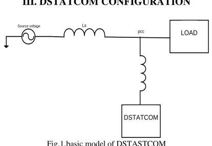
Fig.1.basic model of DSTASTCOM
Fig.1. shows that the basic view of DSTATCOM connected to load through certain inductances. Here in place of DSTATCOM used with an Voltage source fed inverter with DSTATCOM configuration. The VSI is connected aswith neutral point clamped voltage source inverter (VSI) topology is chosen as it provides independent control of each leg of the VSI [7]. A equivalent circuit of DSTATCOM in distribution network is shown in Fig. 2.VSI represented by u V dc is connected to load terminal through an LC filter ( ).
The load terminal is connected tothe PCC (point of common coupling) flowing through an external series inductance Lext. The Vdcisthe voltage maintained across the each dc capacitor and uis the control variable which can be +1 or -1 depending upon switching state. If i, if t, and if c are currents through VSI,DSTATCOM, and Cfc respectively. Vsand Vtare source andload voltages respectively.
IV.MODELLING OF DSTATCOM
A D-STATCOM is basically a converter based distribution flexible AC transmission controller (FACTS), that has many nearer characteristics that of Static Compensator (STATCOM) is showed in fig.3.which is used at transmission level. Hence the D-STATCOM is installed at the distribution level or at load end for dynamic compensation or at end user line terminals. A D-STATCOM is a custom device that has DC link capacitor and Voltage source converter that are shunted, that is able to generate and/or absorb reactive power. The principles of operation of a D-STATCOM are generally based on the conventional rotating synchronous compensator.
Fig.3. schematic of voltage injected DSTATCOM
The compensation of voltage sag/swell can be limited by considering a number of factors, such as loading conditions, power quality problems and types of sag/swell and including finite DSTATCOM power rating. If a DSTATCOM is a successful device, the control is able to handle most sags/swells and the performance must be maximized according to the equipment inserted. Otherwise, the DSTATCOM may not be able to avoid tripping and even cause additional disturbances to the loads.
V.Mathematical Modeling for Voltage Injection by DSTATCOM
Let us Consider the schematic diagram of DSTATCOM shown in Fig.3. A D-STATCOM (Distribution Static Compensator), which is schematically depicted in Fig.3 consists of a two-level Voltage Source Converter (VSC), a dc energy storage device, a coupling transformer connected in shunt to the distribution network through a coupling transformer. The VSC converts the dc voltage
across the storage device in to a set of three-phase ac output voltages. These voltages are in phase and coupled with the ac system through the reactance of the coupling transformer. Suitable adjustment of the phase and magnitude of the D-STATCOM output voltages allows effective control of active and reactive power exchanges between the D-STATCOM and the ac system. Such configuration allows the device to absorb or generate controllable active and reactive power. The VSC connected in shunt with the ac system provides a multifunctional topology which can be used for up to three quite distinct purposes,
1. Voltage regulation and compensation of reactive power.
2. Correction of power factor.
3. Elimination of current harmonics.
Here, such device is employed to provide continuous Voltage regulation using an indirectly controlled converter.
The shunt injected current Ish corrects the voltage sag by adjusting the voltage drop across the system impedance Zth. The value of Ish can be controlled by adjusting the output voltage of the converter [10].
The shunt injected current Ish can be written as,
Ish = IL – IS(4)
Ish = IL – [(VTh – VL)/ZTh] (5)
Ish∠η = IL∠-θ-(Vth/Zth)∠(δ-β)+(VL/Zth)∠-β (6)
Fig.5 Schematic diagram of DSTATCOM control.
[11] with some auxiliary inputs finally iq ref was developed is fed to inverter.
The D-STATCOM system master controller provides flexible voltage and reactive power controlling techniques that supports many power system applications including reactive support and voltage control, fast voltage recovery support, enhancing system voltage stability, improving system transient stability, improving system reliability, improving line capacity utilization, minimizing system losses.
VI. PHOTOVOLTAIC (PV) SYSTEM
In the crystalline silicon PV module, the complex physics of the PV cell can be represented by the equivalent electrical circuit shown in Fig.6. For that equivalent circuit, a set of equations have been derived, based on standard theory, which allows the operation of a single solar cell to be simulated using data from manufacturers or field experiments.
Fig.6. Equivalent Electrical Circuit of a PV Module.
The series resistance RS represents the internal losses due to the current flow. Shunt resistance Rsh, in parallel with diode, this corresponds to the leakage current to the ground. The single exponential equation which models a PV cell is extracted from the physics of the PN junction and is widely agreed as echoing the behavior of the PV cell
(7) The number of PV modules connected in parallel and series in PV array are used in expression. The Vt is also defined in terms of the ideality factor of PN junction (n), Boltzmann’s constant (KB), temperature of photovoltaic array (T), and the electron charge (q). The EAR strategy is carried out by inserting a controllable switching matrix between the PV generator and the central inverter, which allows the electrical reconnection of the available PV modules.
VII.MATLAB/SIMULINK RESULTS Here simulation are carried out in several cases, in that 1) PQ Improvement without DSTATCOM Topology. 2) PQ Improvement with DSTATCOM Topology.
Case 1: PQ Improvement withoutDSTATCOM Topology
Proposed Novel Multifunctional Distributed Compensation Scheme can mitigate several power quality (PQ) problems. In this case, it injects harmonic and reactive components of load currents to make source currents balanced, sinusoidal, and in phase with load voltages in current controlled mode.
Fig.7 Matlab/Simulink Model of without DSTATCOM Topology for PQ Improvement Features
Figure.7.gives the Simulation model of system without DSTATCOM topology. In a distribution system with a non-linear load connected to the system will generates harmonics. A nonlinear load in a power system is characterized by the introduction of a switching action and consequently current interruptions. This behavior provides current with different components that are multiples of the fundamental frequency of the system.These components are called harmonics. The amplitude and phase angle of a harmonic is dependent on the circuit and on the load it drives.
Fig.8.Source current, Load current, Inverter current and source voltage Wave Forms without DSTATCOM Topology.
voltage and currents are in phase with each other, maintain unity power factor. Increased load current will not effect on source performance and vice versa. It showed in phase-a, is shown in fig.8.
Fig.9.THD For without DSTATCOM Topology.
At t = 0.0 s, fault is created by three phase fault at source side. Here there is no any voltage regulation is provided at load side. It can be seen in fig.9; here THD is occurred as 16.58%.
Fig.10.power factor when without dstatcom condition
Fig.10. shows the load angleshows the voltage at dc bus which is regulated voltage during entire operation.
Case 2:PQ Improvement with DSTATCOM Topology.
Here it regulates load voltage at a constant value to protect sensitive loads from voltage disturbances such as sags, swells, transients, and/or fluctuations in voltage controlled mode. However, the objectives of these two modes are different and it can be achieve by proposed DSTATCOM.
Fig.11.Matlab/Simulink Model of with PV Cell based DSTATCOM Topology for PQ Improvement
Recently, developments in power electronics and semiconductor technology have leadimprovements in power electronic systems. Pulse Width Modulation variable speed drives are increasingly applied in many new industrial applications that require superior performance for controlling the power flow for this industrial application requires Facts device, which is operated under distribution system is nothing but distributed compensation scheme.
Fig.12.Simulation Results for Source Current, Load Current and InverterCurrent And source voltage For with DSTATCOM Topology
Fig.13.THD For with DSTATCOM Topology with THD is 1.89% here dstatcom is compensate the error.
Fig.14.Power Factor When With DSTATCOM Condition.
VII.CONCLUSIONS
In this paper, a new converter topology has been proposed with and without DSTATCOM. which has superior features over conventional topologies in terms of the required power switches and isolated dc supplies, control requirements, cost, and reliability with a new control algorithm based multifunctional DSTATCOM is proposed to protect the load from voltage disturbances under stiff source. It has been achieved by placing an external series inductance of suitable value between the source and the load. In addition, instantaneous reference voltage is controlled in such a way that the source currents are indirectly controlled and the DSTATCOM under power quality concerns with near to optimal features with efficient operation.
REFERENCES
[1] Chandan Kumar and Mahesh K. Mishra, "A Multifunctional DSTATCOM Operating Under Stiff Source," IEEE Transactions on Industrial Electronics, vol.61, no.7, pp.3131-3136, July 2014".
[2] A. Bhattacharya and C. Chakraborty, “A shunt active power filter with enhanced performance using ANN-based predictive and adaptive controllers,” IEEE Trans., Ind. Electron., vol. 58, no. 2, pp. 421–428, Feb. 2011.
[3] S. Rahmani, A. Hamadi, and K. Al-Haddad, “A Lyapunov-function based control for a three phase shunt hybrid active filter,” IEEE Trans. Ind. Electron., vol. 59, no. 3, pp. 1418–1429, Mar. 2012.
[4] Mahesh K. Mishra and K. Karthikeyan, “An investigation on design and switching dynamics of a voltage source inverter to compensate unbalanced and nonlinear loads,” IEEE Trans. Ind. Electron., vol. 56, no. 8, pp. 2802–2810, Aug. 2009.
[5] J. Liu, P. Zanchetta, M. Degano, and E. Lavopa, “Control design and implementation for high performance shunt active filters in aircraft
power grids,” IEEE Trans. Ind. Electron., vol. 59, no. 9, pp. 3604–3613, Sep. 2012.
[6] A. Bhattacharya, C. Chakraborty, and S. Bhattacharya, “Parallel connected shunt hybrid active power filters operating at different switching frequencies for improved performance,” IEEE Trans. Ind. Electron., vol. 59, no. 11, pp. 4007–4019, Nov. 2012.
[7] Q.-N. Trinh and H.-H. Lee, “An advanced current control strategy for three-phase shunt active power filters,” IEEE Trans. Ind. Electron., vol. 60, no. 12, pp. 5400–5410, Dec. 2013.
[8] Mahesh K. Mishra, A. Ghosh, and A. Joshi, “Operation of a DSTATCOM in voltage control mode,” IEEE Trans. Power Del., vol. 18, no. 1, pp. 258–264, Jan. 2003.
[9] H. Fujita and H. Akagi, “Voltage-regulation performance of a shunt active filter intended for installation on a power distribution system,” IEEE Trans. Power Electron., vol. 22, no. 3, pp. 1046–1053, May 2007. [10] R. Gupta, A. Ghosh, and A. Joshi, “Performance comparison of VSC based shunt and series compensators used for load voltage control in distribution systems,” IEEE Trans. Power Del., vol. 26, no. 1, pp. 268– 278, Jan. 2011.