Review of Fuzzy Control Based APF for
Power Quality Improvement
Komal K. Ingale1, Prasad D. Kulkarni2
PG Student (EPS), Dept. of EE, KCE’S College of Engineering, Jalgaon, Maharashtra, India1 Assistant Professor, Dept. of EE, KCE’S College of Engineering, Jalgaon, Maharashtra, India2
ABSTRACT:A good power quality is an important factor for the reliable operation of electrical loads. The nonlinear loads such as compact fluorescent lamps, light-emitting diode lamps, switching mode power suppliers, induction motors give rise to serious challenges in power quality for power systems. Due to the non- linear load connected in the power system harmonics will presented, which effects power quality of the at the distribution level. Conventional PI, PD and PID controllers and fuzzy logic controllers are used to improve power quality. Fuzzy logic controllers (FLC’s) have the advantages over the conventional controllers: they are cheaper to develop, fast, robust, they cover a wider range of operating conditions, and they are more readily customizable in natural language terms. Fuzzy logic controller is conjunction with the PLL synchronizing circuit as the controller for shunt APF facilitates improving power quality. For power quality improvement separate converter with shunt APF is used. The APF is controlled by d-q theory with hysteresis controller is used to generate gate pulses to inverter switches. The FLC ensures that the dc-side capacitor voltage is nearly constant with small ripple besides extracting fundamental reference currents. The PLL synchronizing circuit assists the active filter to function even under distorted voltage or current conditions. The shunt APF system is implemented with voltage source inverter and is connected in parallel at PCC for filtering the current harmonics and compensating the reactive power in traction system. The APF controlled by Fuzzy controller is modelled using MATLAB\Simulink. Another application of fuzzy logic controller are defence, underwater target recognition, automatic target recognition of thermal infrared images, naval decision support aids, control of a hypervelocity interceptor, satellite altitude control; flow and mixture regulation in aircraft de-icing vehicles automotive etc.
KEYWORDS: APF (Active Power Filter), Hysteresis Current Controller (HCC), PCC (Point of common coupling), Fuzzy logic controller.
I. INTRODUCTION
A good power quality is an important factor for the reliable operation of electrical loads.AC power supply feeds different kind of linear and nonlinear loads in traction applications. The non-linear loads produce harmonics and reactive power related problems in the utility systems. The harmonic and reactive power cause poor power factor and distort the supply voltage at the customer service point, increased power losses in customer equipment, power transformers and power lines, flicker, shorter life of organic insulation [1].
Conventionally passive filters are used to compensate the lagging power factor of the reactive load and suppress the harmonic problems, but these passive filters are having some drawbacks; such as resonance, large in size, weight, and are limited too few harmonics. Recently, Active Power Filters (APF) is developed for compensating harmonics and reactive power simultaneously. There are two main categories of APF exist: shunt filters and series filters. The active power filter topology can be connected in series for voltage harmonic compensation and in parallel for current harmonic compensation. Most of the applications need current harmonic compensation, so the shunt active filter is popular than series active filter. The shunt active power filter has the ability to keep the mains current balanced and sinusoidal after compensation regardless of whether the load is non-linear [1].
ISSN (Print) : 2320 – 3765 ISSN (Online): 2278 – 8875
I
nternational
J
ournal of
A
dvanced
R
esearch in
E
lectrical,
E
lectronics and
I
nstrumentation
E
ngineering
(A High Impact Factor, Monthly, Peer Reviewed Journal)
Website: www.ijareeie.com
Vol. 7, Issue 5, May 2018
current control techniques. The proposed concept for shunt APF system is validated through extensive simulation with nonlinear load. [2]
II. LITRATURE SURVEY
Harmonics
Harmonic is multiple of the fundamental frequency and it can be voltage and current in an electric power system due to non-linear electric loads. Examples of nonlinear loads include transistors, electrical motors, and the non-ideal transformer. Non-linear loads create disturbances in the fundamental harmonic, which produce all types of harmonics. Harmonic frequencies in the power system are a frequent cause of power quality problems. Harmonics in power systems result in increased heating in the equipment and conductors, misfiring in variable speed drives, and torque pulsations in motors.
Current Harmonics
In a normal alternating current power system, the current varies sinusoidally at a specific frequency, usually 50 Hz. When a linear electrical load is connected to the system, it draws a sinusoidal current at the same frequency as the voltage.
Current harmonics are caused by non-linear loads. When a non-linear load, such as a rectifier is connected to the system, it draws a current that is not necessarily sinusoidal. The current waveform can become quite complex, depending on the type of load and its interaction with other components of the system. The current waveform as described through Fourier series analysis, it is possible to deconstruct it into a series of simple sinusoids, which start at the power system fundamental frequency and occur at integer multiples of the fundamental frequency.
Total Harmonic Distortion
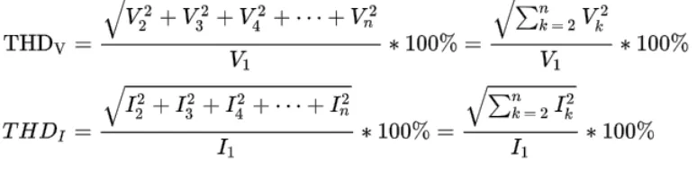
Total harmonic distortion (THD) is a common measurement of the level of harmonic distortion present in power systems. THD can be related to either current harmonics or voltage harmonics, and it is defined as the ratio of total harmonics to the value at fundamental frequency times 100%.
EXISTING CONTROL STRATEGIES
PI-Controller
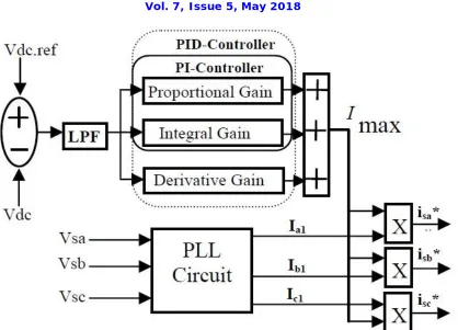
Fig. 1 shows the block diagram of the proposed PI control scheme for the active power filter. The DC side capacitor voltage is sensed and compared with a reference voltage. This error
e =Vdc, ref−Vdcat
the nth sampling instant used as input for PI controller. The error signal is passed through Butterworth design based Low Pass Filter (LPF). The LPF filter has cut off frequency at 50 Hz that can suppress the higher order components and allows only fundamental components. The PI controller is estimate the magnitude of peak reference current Imax and control the dc-side capacitor voltage of voltage source inverter. Its transfer function is represented as
Fig. 1 Blok Diagram of the PLL with PI and PID controller
Where, [ KP=0.7] is the proportional constant that determines the dynamic response of the Dc side voltage control and [ KI =23] is the integration constant that determines it’s settling time. The proportional integral controller is eliminating steady state error in the DC-side voltage.
PID Controller
Fig. 1 shows the block diagram of the proposed Proportional Integrator Derivative (PID) control scheme of an active power filter. The error
e = Vdc, ref−Vdcat
The nth sampling instant issued as input for PID controller. The error signal is passed through LPF; that can suppress the higher order components and pass only the fundamental component.
The PID controller is a linear combination of the P, I and D controller. Its transfer function can be represented as
……..(2)
ISSN (Print) : 2320 – 3765 ISSN (Online): 2278 – 8875
I
nternational
J
ournal of
A
dvanced
R
esearch in
E
lectrical,
E
lectronics and
I
nstrumentation
E
ngineering
(A High Impact Factor, Monthly, Peer Reviewed Journal)
Website: www.ijareeie.com
Vol. 7, Issue 5, May 2018
III. SYSTEM SETUP
Comparison Between PI, PID And Fuzzy Logic Controller
PARAMETERS PI CONTROLLER PID CONTROLLER FUZZY LOGIC
CONTROLLER
Definition
The proportional integral controller produces an output which is the combination of
outputs of the proportional and integral controllers.
The proportional integral derivative controller produces an output, which is the combination of the outputs of proportional, integral and derivative controllers.
Fuzzy controller converts the human linguistic concepts into an automatic control strategy without any complicated mathematical model.
Input variables PI controller uses numerical variables. PID controller uses numerical variables. Fuzzy logic uses Linguistic variables
Function
The proportional integral controller is used to decrease the steady state error without affecting the stability of the system.
The proportional Integral derivative controller is used to improve the stability of the system and to decrease steady state error.
Fuzzy controller improves the stability of the system and decrease steady state error than PID controller.
DC voltage Settling time
More Less than PI controller Very less
Stability
It tends to make the system unstable because it responds slowly towards the
produced error.
It tends to make the system stable because it eliminates steady state error more faster than PI
controller.
Fuzzy controller make system stable.
Performance in non linear
system
Variable Variable Stable
Total harmonic distortion (THD)
More Less than PI controller Very less
Why Should We Use Fuzzy Controllers? It is very robust
It can be easily modified
It can use multiple inputs and outputs sources
Much simpler than its predecessors (linear algebraic equations)
It is very quick and cheaper to implement.
Architecture of Fuzzy Logic Controller
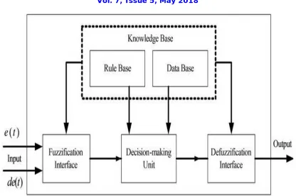
The architecture of the fuzzy logic controller shown in Fig. 2 includes four components: Fuzzifier, Rule Base, Fuzzy Inference Engine (decision making unit), and Defuzzifier.
Fuzzifier:
Fig. 2 Architecture of Fuzzy Logic Controller
Rule Base:
The rule base contains a set of fuzzy if-then rules which defines the actions of the controller in terms of linguistic variables and membership functions of linguistic terms. The Rule base stores the linguistic control rules required by rule evaluator (decision making logic).The output of the fuzzy controller is estimating the magnitude of peak reference current. This peak reference current comprises active power demand of the non-linear load and losses in the distribution system. The peak reference current is multiplied with PLL output for determining the desired reference current.
Database:
The Database stores the definition of the triangular membership function required by fuzzifier and defuzzifier.
Fuzzy Inference Engine:
The fuzzy inference engine applies the inference mechanism to the set of rules in the fuzzy rule base to produce a fuzzy output set. This involves matching the input fuzzy set with the premises of the rules, activation of the rules to deduce the conclusion of each rule that is fired, and combination of all activated conclusions using fuzzy set union to generate fuzzy set output.
Defuzzifier:
The rules of fuzzy logic controller generate required output in a linguistic variable (Fuzzy Number), according to real world requirements; linguistic variables have to be transformed to crisp output (Real number). This selection of strategy is a compromise between accuracy and computational intensity.
How Fuzzy Logic Controller works?
ISSN (Print) : 2320 – 3765 ISSN (Online): 2278 – 8875
I
nternational
J
ournal of
A
dvanced
R
esearch in
E
lectrical,
E
lectronics and
I
nstrumentation
E
ngineering
(A High Impact Factor, Monthly, Peer Reviewed Journal)
Website: www.ijareeie.com
Vol. 7, Issue 5, May 2018
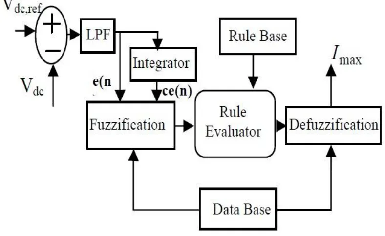
fuzzy logic control scheme. In order to implement the control algorithm of a shunt active power filter in a closed loop, the dc capacitor voltage VDC is sensed and then compared with the desired reference value VDC,ref. The error signal:
e =VDC, ref −VDC
is passed through LPF with a cut off frequency that pass only the fundamental component. The error signal e(n) and integration of error signal is termed as ce(n) are used as inputs for fuzzy processing. The output of the fuzzy logic controller limits the magnitude of peak reference current Imax. This current takes care of the active power demand of the non-linear load and losses in the distribution system. The switching signals for the PWM inverter are generated by comparing the actual source currents isa, isb , isc with the reference current (isa*,isb*,isc *) using the hysteresis current control method.
Fig 3 Fuzzy Logic Controller
Hysteresis Current Controller (HCC)
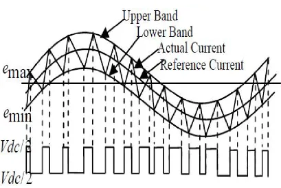
HCC is utilized independently for each phase and directly generates the switching signals for three phase voltage source inverter. An error signal e(t) is the difference between the desired current I ref (t) and the actual current I actual (t).
If the error current exceeds the upper limit of the hysteresis band, the upper switch of the inverter arm is turned OFF and the lower switch is turned ON. As a result, the current start to decay that is shown in Fig. 3. If the error current crosses the lower limit of the hysteresis band, the lower switch of the inverter arm is turned OFF and the upper switch is turned ON.As a result, the current gets back into the hysteresis band [3].
The switching performance as follows:
...(3)
Fig. 4 Diagram of hysteresis current control
Fuzzy Control Of Active Power Filter (APF)
The identified Load frequency control and interconnection problems can be effectively reduced by controlling AGC. Fuzzy logic is wide employed in controlling technique. The word "fuzzy" maintain fact that the logic concerned that can't be expressed as "true" or "false" however rather as "partially true". Though various approaches like genetic algorithms and ANN will perform even as well as formal logic in several cases, formal logic has the advantage that the answer to the matter is forged in terms that human operators will perceive, so their expertise is employed in the controller of prognosticative current control. The linguistic variables area unit outlined as (NB, NM, NS, Z, PS,PM, PB) that means negative big, negative medium, negative sall, zero, positive small, positive medium and positive big.
ISSN (Print) : 2320 – 3765 ISSN (Online): 2278 – 8875
I
nternational
J
ournal of
A
dvanced
R
esearch in
E
lectrical,
E
lectronics and
I
nstrumentation
E
ngineering
(A High Impact Factor, Monthly, Peer Reviewed Journal)
Website: www.ijareeie.com
Vol. 7, Issue 5, May 2018
IV. CIRCUIT DIAGRAM OF SYSTEM
A three-phase inverter for traction system requiring power quality features, such as harmonic and reactive power compensation by using fuzzy logic controller. The proposed active power filter with fuzzy control and the effectiveness of the associated harmonic and reactive power compensation are simulated using Matlab/Simulink.
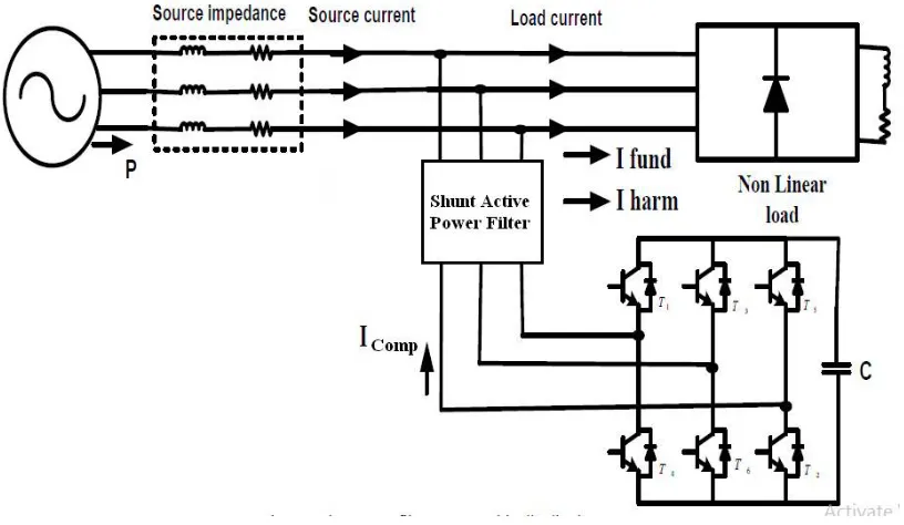
Fig. 5 Active Power Filter With Fuzzy Logic Controller in Traction System
Fig. 5 shows active power filter with fuzzy logic controller in 25KV traction system. Active power filter generates compensating currents and induces these generated compensated currents in to the system thus mitigating harmonics in the system. Unwanted neutral currents might flow caused due to non-linear loads with uncompensated and unbalanced systems. In this case, a three phase APF can deliver compensation. Active power filters are of different types. Series compensator, shunt compensator or combination of both series and shunt compensator called UPQC. Here in this paper shunt active power filter was considered to mitigate the harmonic pollution in the system containing induction motor as non linear load. A typical arrangement of inverter as shunt active power filter was connected is showed in fig. 5. This is a converter based APF with VSI configuration. VSI configured APF is low cost, simple, expandable to multi-level and consists of a self supporting DC Voltage. This shunt active power filter can effectively mitigate harmonics. The APF shunted at PCC in distribution system and also at PCC we have AC source is connected with source impedance. This three phase ac source is supplies a active power to load and load is connected with nonlinear load which has load reactive power demand is high on source and harmonics will generated. To eliminate problems will be produced by load by using APF is shunted with system [1].
V. CONCLUSION
AKNOWLEDGEMENT
I would like to express the deepest appreciation to my guide Prof. P.D. Kulkarni for their help to complete this paper. I would also like to thank my HOD Prof. K.M. Mahajan for their great support, also thanks to KCE‟s Engineering
College to provide lab and instrument to me for my work. At last but not least, At least but not last, I am thankful my parents who support and encourage me for this works.
REFERENCES
[1] 2016, “Fuzzy control based APF with DG integration for power quality improvement in distribution system”; Mr. Kranthi Kumar, International conference on Signal Processing, Communication, Power and Embedded System .
[2] August 2015,“Fuzzy logic controller based APF with advanced power quality”, Lavudya Shankar, International journal of scientific engineering and technology research.
[3] June 2011,“Performance and investigation of hybrid filters for power quality improvement”;Ravish Khanna, The 5th International Power Engineering and Optimization Conference.
[4] 2010,“PLL with PI, PID and fuzzy logic controllers based shunt active power line conditioners” Karuppanan ,International Conference on Power Electronics, Drives and Energy Systems.
[5] Sep -2017, “Improving efficiency of active power filter for renewable power generation systems by using predictive control method and fuzzy logic control method”, Prahlada, International Research Journal of Engineering and Technology.
[6] April 2003,“Implementation and performance of cooperative control of shunt active filters for harmonic damping throughout a power distribution system”, Pichai Jintakosonwit, IEEE transactions on industry applications, vol. 39, no. 2.
[7] May 2014 “Hybrid active power filter for power quality improvement” ,Kavya Mittal, Ankita Kosti, International Journal Of Emerging Technology And Advanced Engineering Volume 4, Issue 5.
[8] Oct-2012 ,“ A comparative analysis of PI controller and fuzzy logic controller for hybrid active power filter using dual instantaneous power theory” G. Satya Narayana, Ch. Narendra Kumar, Ch. Rambabu, International Journal of Engineering Research & Development, Vol-4, Issue-6, p.p. 29-39.
[9] November 2014, “Improvement of power quality using hybrid active power filter in three- phase three wire system applied to induction drive” B. Mohan Reddy, G. Balasundaram, Journal Of Advanced Research In Electrical, Electronics And Instrumentation Engineering, Vol. 3, Issue 11.
[10] Mar. 1997. “Three-phase four-wire shunt active filter control strategies,” M. Aredes, J. Hafner, and K. Heumann, IEEE Trans. Power Electron., vol. 12, no. 2, pp. 311–318.
[11] Aug. 2010. “Dynamic hysteresis current control to minimize switching for three-phase four-leg VSI topology to compensate nonlinear load,” N. Prabhakar and M. Mishra, IEEE Trans. Power Electron., vol. 25, no. 8, pp. 1935–1942.
[12] Feb. 2012. “A robust adaptive control strategy of active power filters for power-factor correction, harmonic compensation, and balancing of nonlinear loads,” R. de Araujo Ribeiro, C. de Azevedo, and R. de Sousa, IEEE Trans. Power Electron., vol. 27, no. 2, pp. 718–730.
[13] May 2009. “A predictive control scheme for current-source rectifiers,” P. Correa, J. Rodriguez, I. Lizama, and D. Andler, IEEE Trans. Ind. Electron., vol. 56, no. 5, pp. 1813–1815.
BIOGRAPHY
Komal Kishor Ingale has completed Graduate degree B.E. in Electrical Engineering in 2016 from Government College of Engineering, Jalgaon. She is Currently working towards Master of Engineering in Electrical Power System at KCE’S College of Engineering and Technology, Jalgaon, Maharashtra, India.
Prof. P.D.Kulkarni is working as Assistant professor in Electrical