Design and Implementation of 16-bit Montgomery Modular
Multiplication
B Roja Pavitra, P.G.STUDENT, Kakinada Institute of Engineering and Technology for Women
R Sathya Veni, Asst.Prof, Kakinada Institute of Engineering and Technology for Women
Abstract
Modular multiplication is the core operation in public-key cryptographic algorithms such as RSA
and the Diffie-Hellman algorithm. The efficiency of the modular multiplier plays a crucial role in the
performance of these cryptographic methods. In this paper we are designing a 16-bit Montgomery
modular multiplication with PASTA ADDER. In addition, a mechanism that can detect and skip the
unnecessary carry-save addition operations in the PASTA architecture while maintaining the short critical
path delay is developed. Experimental results show that the proposed Montgomery modular multiplier can
achieve higher performance and significant area–time product improvement when compared with
previous designs.
Index terms: low-cost architecture, Montgomery modular multiplier, public-key cryptosystem.
I. INTRODUCTION:
The multiplication of large integers is
one of the core operations in public key
cryptography. In order to provide the required
cryptographic strength, the operand size has
been growing continuously. During the earlier
days of the RSA algorithm[1], the researchers
believed that 512-bit size was sufficient; a few
years of research in factoring RSA moduli
immediately brought the key size to 1024 bits.
Currently many implementations already
increase their key size to 2048 bit, for example,
the root keys issued for SSL, while NIST [2]
recommends 3072-bit keys for protection
beyond the year 2030. 1 Therefore, using RSA
to provide long term protection, 3072-bit or even
larger integer modular multiplications need to be
performed. Consequently, high performance
long integer modular multiplier is in demand for
practical use of the RSA.
Montgomery Modular Multiplication
(MMM) [3] algorithm is the most popular
algorithm to perform modular multiplications to
date. It has been extensively studied, and several
variants of MMM have been proposed for both
hardware and software platforms[4], [5], [6], [7],
[8], [9], [10], [11]. To compute xy mod n using
the original MMM, three l-bit multiplications
dominate the computation time (l is the bit
of multiplication will benefit the performance of
MMM significantly. The asymptotic
complexities of multiplication algorithms from
the schoolbook method to the Furer method ¨ are
listed in Table 1. The GMP library [16] provides
efficient software implementations for most of
these algorithms. However, it only focuses on
software. There are many hardware realizations
of these multiplication algorithms: the
schoolbook[4], [5], [9], [10] and Karatsuba
methods [12], [17], [18], but few on Schonhage-
¨ Strassen Algorithm (SSA) [7].
Montgomery modular multiplication [3]
is an efficient modular algorithm when the
modulus n is without specific form. By adding
constraints on the parameters, Walter [26]
proposed the MMM without conditional
subtraction algorithm and it is given in
Algorithm 1. In MMM, r is typically a power of
2 for the ease of computation.
II. PREVIOUS WORK:
The Montgomery modular
multiplication algorithm was designed to avoid
division in modular multiplications. Given two
n-bit inputs, X and Y, this algorithm gives Z = X
· Y · R−1 mod M, where R equals to 2n and M
is the n-bit modulo. Algorithm 1 shows the
Radix-2w Montgomery modular multiplication
algorithm in detail. A modified Montgomery
multiplication algorithm was proposed to avoid
the conditional final
In recent years, the Montgomery
modular multiplication has been widely
implemented in software and hardware. For
example, In [14], it was implemented on an
8-bit microcontroller. In [6] It was implemented
on an high-end TI DSP (TMS320C6201)
showed that the software implementations on
general purpose CPU can be sped up by
extending the ISA. These software
implementations are highly flexible, whereas the
performance is limited. The hardware
implementations of the Montgomery
multiplication were also widely investigated.
Researchers have deployed various
architectures, such as bipartite multipliers[15]
and systolic arrays [16, 17, 18] to achieve high
throughput. In order to obtain some flexibility,
reconfigurable data path [11] for the
Montgomery modular multiplication was also
explored. However, there is still a gap between
the flexibility and performance. One way to
bridge the gap is using parallel computation with
programmable devices, e.g., dual-mac DSP [6].
III. PROPOSED 16-bit
MONTGOMERY
MULTIPLICATION:
In this section, we propose a new
SCS-based Montgomery MM algorithm to reduce the
critical path delay of Montgomery multiplier. In
addition, the drawback of more clock cycles for
completing one multiplication is also improved
while maintaining the advantages of short
Critical Path Delay Reduction:
The critical path delay of SCS-based
multiplier can be reduced by combining the
advantages of FCS-MM-2 and SCS-MM-2. That
is, we can pre compute D = B + N and reuse the
PASTA architecture to perform B+N and the
format conversion. Fig. 7(a) and (b) shows the
modified SCS-based Montgomery multiplication
(MSCS-MM) algorithm and one possible
hardware architecture, respectively. The Zero_D
circuit in Fig. 7(b) is used to detect whether SC
is equal to zero, which can be accomplished
using one NOR operation. The Q_L circuit
decides the qi value according to step 7 of Fig.
7(a). The carry propagation addition operations
of B + N and the format conversion are
performed by the one-level CSA architecture of
the MSCS-MM multiplier through repeatedly
executing the carry-save addition (SS, SC) = SS
+ SC + 0 until SC = 0. In addition, we also pre
compute Ai and qi in iteration i−1 (this will be
explained more clearly in Section III-C) so that
they can be used to immediately select the
desired input operand from 0, N, B, and D
through the multiplexer M3 in iteration i.
Therefore, the critical path delay of the
MSCS-MM multiplier can be reduced into TMUX4 +
TFA. However, in addition to performing the
three-input carry-save additions [i.e., step 12 of
Fig. 7(a)] k + 2 times, many extra clock cycles
are required to perform B + N and the format
conversion via the PASTA architecture because
they must be performed once in every MM.
Furthermore, the extra clock cycles for
performing B+N and the format conversion
through repeatedly executing the carry-save
addition (SS, SC) = SS +SC +0 are dependent on
the longest carry propagation chain in SS + SC.
If SS = 111…1112 and SC = 000…0012, the
one-level CSA architecture needs k clock cycles
to complete SS + SC.
Clock Cycle Number Reduction:
To decrease the clock cycle number, a
CCSA architecture which can perform one
three-input carry-save addition or two serial
two-input carry-save additions is proposed to
substitute for the one-level CSA architecture in
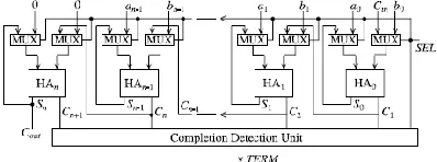
Fig. 7(b)The general architecture of the adder is
Fig 1. Block Diagram of PASTA
Each state is represented by (Ci+1 Si) pair where
Ci+1, Si represent carry out and sum values
respectively, from the ith bit adder block. During
the initial phase, the circuit merely works as a
combinational HA operating in fundamental
mode. It is apparent that due to the use of HAs.
Let Si j
and C ji+1 denote the sum and carry,
respectively, for ith bit at the j th iteration. The
initial condition ( j = 0) for addition is
S0i= ai ⊕bi
C0i+1= ai bi .
The j th iteration for the recursive addition is
formulated by
Sji= S i j−1⊕
C i j
−1 , 0 ≤ i < n (2)
C i+1
j=
S i j−1
C i j−1
, 0 ≤ i ≤ n. (3)
The recursion is terminated at kth iteration when
the following condition is met:
Ckn+ C k
n−1+ ・・ ・+C
k
1= 0, 0 ≤ k ≤ n. (4)
Now, the correctness of the recursive
formulation is inductively proved as follows.
Theorem 1: The recursive formulation
of (1)–(4) will produce correct sum for any
number of bits and will terminate within a finite
time.
Proof: We prove the correctness of the
algorithm by induction on the required number
of iterations for completing the addition
(meeting the terminating condition).
Basis: Consider the operand choices for
which no carry propagation is required, i.e., C0i
= 0 for ∀i, i ∈ [0..n]. The proposed
formulation will produce the correct result by a
single-bit computation time and terminate
instantly as (4) is met.
Induction: Assume that Cki+1≠ 0 for
some I th bit at k th iteration.
Let l be such a bit for which Ckl+1= 1. We show
that it will be successfully transmitted to next
higher bit in the (k + 1)th iteration.
As shown in the state diagram, the kth iteration
of lth bit state(Ckl+1, S
k
l ) and (l + 1)th bit state
(Ckl+2, S
k
l+1) could be in any of (0, 0), (0, 1), or
(1, 0) states. As Ckl+1= 1, it implies that S
k l=0.
Hence, from (3), Ck+1l+1= 0 for any input
condition between0 to l bits.
We now consider the (l + 1)th bit state
(Ckl+2,S
k
l+1) for kth iteration. It could also be in
any of (0, 0), (0, 1), or (1, 0) states. In (k+1)th
iteration, the (0, 0) and (1, 0) states from the kth
iteration will correctly produce output of (0, 1)
following (2) and (3). For (0, 1) state, the carry
successfully propagates through this bit level.
We modify the 4 to 1 multiplexer M3 in fig(b)
into a simplified multiplier SM3 as shown in fig.
8(d) because one of its inputs is zero, where
denotes the INVERT operation. Note that M3
has been replaced by SM3 in the proposed
PASTA architecture.
According to the delay ratio shown in
Table II, TS M3 (i.e., 0.68 × TFA) is
approximate to TMUX3 (i.e., 0.63 × TFA) and
TMUXI2 (i.e., 0.23 × TFA) is smaller than
TXOR2 (i.e., 0.34×TFA). Therefore, the critical
path delay of the proposed PASTA architecture
in Fig. 8(b) is approximate to that of the
one-level CSA architecture in Fig. 8(a). As a result,
steps 3 and 15 of Fig. 7(a) can be replaced with
(SS, SC) = 2H_CSA(SS, SC) and (SS[k + 2],
SC[k + 2]) = 2H_CSA (SS[k + 2], SC[k + 2]) to
reduce the required clock cycles by
approximately a factor of two while maintaining
a short critical path delay.
In addition, we also skip the
13) of Fig. 7(a) to further decrease the clock
cycles for completing one Montgomery MM.
The crucial computation in the for loop of Fig.
7(a) is performing the following three-to-two
carry-save addition:
(SS[i + 1], SC[i + 1]) = (SS[i] + SC[i] + x)/2 (1)
where the variable x may be 0, N, B, or D
depending on the values of Ai and qi . The
computation process of (1) is shown in Fig. 9.
When Ai = 0 and qi = 0, x is equal to 0 and
SS[i]0 must be equal to SC[i]0 because the sum
of SS[i]0 + SC[i]0 + x0 is equal to 0. That is, if
Ai = 0 and qi = 0, then SS[i]0 = SC[i]0. Based
on this observation, we can conclude that the
sum of the carry propagation addition SS[i
+1]k+1:0 + SC[i + 1]k+1:0 is equal to the sum
of the carry propagation addition SS[i]k+1:1 +
SC[i]k+1:1 when Ai = qi = 0 and SS[i]0 =
SC[i]0 = 0. As a result, the computation of (1) in
iteration i can be skipped if we directly right
shift the outputs of one-level CSA architecture
in the (i − 1)th iteration by two bit positions (i.e.,
divided by 4) instead of one bit position (i.e.,
divided by 2) when Ai = qi = 0 and SS[i]0 =
SC[i]0 = 0.
Accordingly, the signal skipi+1 used in
the ith iteration to indicate whether the
carry-save addition in the (i + 1)th iteration will be
skipped can be expressed as
skipi+1 = ∼(Ai+1 ∨ qi+1 ∨ SS[i + 1]0)
where ∨ represents the OR operation. If skipi+1
Fig 1. SCS-MM-NEW multiplier
generated in the ith iteration is 0, the carry-save
addition of the (i + 1)th iteration will not be
skipped. In this case, qi+1 and Ai+1 produced in
the ith iteration can be stored in FFs and then
used to fast select the value of x in the (i +1)th
iteration. Otherwise (i.e., skipi+1 = 1), SS[i + 1]
and SC[i + 1] produced in the ith iteration must
be right shifted by two bit positions and the next
clock cycle will go to iteration i + 2 to skip the
carry-save addition of the (i + 1)th iteration. In
this situation, not only qi+1 and Ai+1 but also
qi+2 and Ai+2 must be produced and stored to
FFs in the ith iteration to immediately select the
value of x in the (i + 2)th iteration without
lengthening the critical path. Therefore, the
selection signals (denoted as qˆ and Aˆ) for
choosing the proper value of x in the next clock
cycle must be picked from (qi+1, Ai+1) or
(qi+2, Ai+2) according to the skipi+1 signal
produced in the ith iteration. That is, (qˆ, Aˆ) =
(qi+2, Ai+2) if skipi+1 = 1. Otherwise, (qˆ, Aˆ)
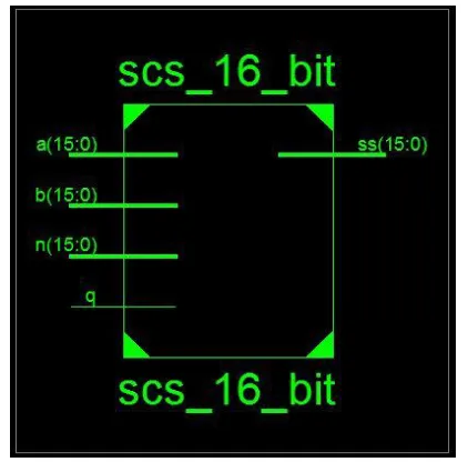
FIG 2: Block diagram of 16-BIT SCS NEW
MULTIPLIER
FIG 3:SIMULATION RESULT OF 16-BIT
SCS NEW MULTIPLIER
IV. CONCLUSION:
SCS-based multipliers maintain the
input and output operands of the Montgomery
MM in the format to escape from the format
conversion, leading to fewer clock cycles but
larger area than SCS-based multiplier. To
enhance the performance of Montgomery MM
while maintaining the low hardware complexity,
this paper has modified the SCS-based
Montgomery multiplication algorithm and
proposed Design and implementation of 16-bit
Montgomery modular multiplier. The proposed
multiplier used PASTA architecture and skipped
the unnecessary carry-save addition operations
to largely reduce the critical path delay and
required clock cycles for completing one MM
operation. Experimental results showed that the
proposed approaches are indeed capable of
enhancing the performance of radix-2
CSA-based Montgomery multiplier while maintaining
low hardware complexity
ACKNOWLEDGMENT:
The authors would like to thank the
reviewers for their many constructive comments
and suggestions in improving this paper. They
would also like to thank the contributions of
Taiwan Semiconductor Manufacturing Company
Limited and National Chip Implementation
Center, Taiwan, for their support in technology
data.
REFERENCES:
[1] R. L. Rivest, A. Shamir, and L. Adleman, “A
method for obtaining digital signatures and
public-key cryptosystems,” Commun. ACM,
vol. 21, no. 2, pp. 120–126, Feb. 1978.
[2] V. S. Miller, “Use of elliptic curves in cryptography,” in Advances in Cryptology.
Berlin, Germany: Springer-Verlag, 1986, pp.
[3] N. Koblitz, “Elliptic curve cryptosystems,”
Math. Comput., vol. 48, no. 177, pp. 203–209,
1987.
[4] P. L. Montgomery, “Modular multiplication without trial division,” Math. Comput., vol. 44,
no. 170, pp. 519–521, Apr. 1985.
[5] Y. S. Kim, W. S. Kang, and J. R. Choi,
“Asynchronous implementation of 1024-bit modular processor for RSA cryptosystem,” in
Proc. 2nd IEEE Asia-Pacific Conf. ASIC, Aug.
2000, pp. 187–190.
[6] V. Bunimov, M. Schimmler, and B. Tolg, “A
complexity-effective version of Montgomery’s
algorihm,” in Proc. Workshop Complex.
Effective Designs, May 2002.
[7] H. Zhengbing, R. M. Al Shboul, and V. P.
Shirochin, “An efficient architecture of
1024-bits cryptoprocessor for RSA cryptosystem
based on modified Montgomery’s algorithm,” in
Proc. 4th IEEE Int. Workshop Intell. Data
Acquisition Adv. Comput. Syst., Sep. 2007, pp.
643–646. [8] Y.-Y. Zhang, Z. Li, L. Yang, and
S.-W. Zhang, “An efficient CSA architecture for
Montgomery modular multiplication,”
Microprocessors Microsyst., vol. 31, no. 7, pp.
456–459, Nov. 2007.
[9] C. McIvor, M. McLoone, and J. V.
McCanny, “Modified Montgomery modular
multiplication and RSA exponentiation
techniques,” IEE Proc.- Comput. Digit. Techn.,
vol. 151, no. 6, pp. 402–408, Nov. 2004.
[10] S.-R. Kuang, J.-P. Wang, K.-C. Chang, and
H.-W. Hsu, “Energy-efficient high-throughput
Montgomery modular multipliers for RSA
cryptosystems,” IEEE Trans. Very Large Scale
Integr. (VLSI) Syst., vol. 21, no. 11, pp. 1999–
2009, Nov. 2013.
R.Sathya Veni Received the B.Tech. degree from Pragati Engineering College, Surampalem . She awarded M.Tech. degree in VLSISD from Sri Vishnu Engineering College for Women, Bhimavaram.
B Roja Pavitra pursuing M.Tech. VLSI&ES in
Kakinada Institute of Engineering Technology
for Women, Korangi. She received Bachelor
degree in Department of Electronics and
Communication Engineering from Kakinada