ABSTRACT
MENJOGE, ZEHLAM, Software Development using the Knowledge Insight Approach.
(Under the direction of Dr. Thomas L. Honeycutt).
Software development processes currently in use often result in the production of low-quality software. The earlier the properties such as quality, security, safety and reliability are addressed during the software development life cycle, the lower is the
development cost and the greater is the probability that the end product functions with no unintended consequences. Unclear and inadequate requirements, unexpected problems
during implementation, unwise decisions made in the beginning stages of the projects are some of the reasons, due to which changes may be required in the later stages of the project. A good software development model is one which accommodates changes, has
the ability to adapt well to them and minimizes budget and schedule overruns.
The Knowledge Insight Model (KIM) is an iterative software development
process. It is flexible enough to accommodate changes at any point during the software development life cycle. KIM is also a higher abstraction of many of the existing software development processes. It consists of four related models, namely, the Framer, the
Maker, the Sharer and the Finder. The Framer is responsible for planning the course of action to be taken and defining the strategies, activities and tasks that are required for
The purpose of this thesis is to perform a comparative analysis of the Knowledge Insight Model with some other commonly used models, namely, the Waterfall Model, the
Spiral model, the Rational Unified Process (RUP) and Extreme Programming (XP). These models are representatives of various classes of models. By studying each one of
them, an understanding of the classes to which they belong, may be developed. The criteria for comparing them are based on the various aspects such as their structure and usability and the system’s products, property and success models. This analysis serves to
evaluate KIM. The results of this analysis show that the KIM is very flexible. It is also suitable for use as a software development model when evolutionary prototyping is
Software Development using the Knowledge Insight Approach
By
Zehlam Menjoge
A thesis submitted to the Graduate Faculty in partial fulfillment of the requirements for the Degree of
Master of Science in COMPUTER SCIENCE
Department of Computer Science
North Carolina State University 2003
Approved By _________________________________________________
Dr. Thomas L. Honeycutt, Chairperson of Advisory Committee
_________________________________________________
Dr. Mladen A. Vouk
_________________________________________________
Dr. Edward Davis
To my grandparents, Mrs. Nalini Menjoge and Mr. Sitaram Menjoge, and my father, Mr. Shrikant Menjoge
BIOGRAPHY
Zehlam Menjoge was born in the city of Bombay in India. She went to Canossa Convent High School (1983 – 1995), Ramnivas Ruia Junior College (1995 – 1997) and
Padmabhushan Vasantdada Patil Pratishthan’s College of Engineering (1997 – 2001), where she completed her B.E. in Computer Engineering. At the time of this writing, she is working towards her M.S. in Computer Science at the North Carolina State University
ACKNOWLEDGEMENTS
I thank Dr. Thomas L. Honeycutt for his help and guidance in completing this thesis. I also thank my committee members, Dr. Mladen A. Vouk and Dr. Edward Davis for their
helpful suggestions during the course of my thesis.
I thank my grandparents and my father for their constant encouragement. I also thank all
TABLE OF CONTENTS
LIST OF FIGURES ... vii
LIST OF TABLES ... viii
1. INTRODUCTION ... 1
1.1 Research Motivation ... 1
1.2 Background issues and problems... 2
1.3 Goals for the thesis... 2
1.4 The Knowledge Insight Model (KIM) [5] ... 3
1.5 Contributions of this thesis ... 4
1.6 Thesis Layout... 5
2. SOFTWARE PROCESS MODELS ... 6
2.1 Overview of Software ... 6
2.2 The need for a good software development process ... 7
2.3 Software Process Models ... 8
2.3.1 The Waterfall Model... 8
2.3.2 The Spiral Model ... 13
2.3.3 The Rational Unified Process (RUP) ... 16
2.3.4 Extreme Programming (XP) ... 20
2.4 Selecting an appropriate Software Process Model... 23
3. THE KNOWLEDGE INSIGHT MODEL (KIM)... 25
3.1 Overview of KIM... 25
3.2 External & Internal Discover & Refine ... 26
3.3 PDCA Cycle... 27
3.4 The Knowledge Insight Model ... 27
3.4.1 Framer ... 29
3.4.2 Maker ... 31
3.4.3 Sharer ... 32
3.4.4 Finder ... 34
A summary of functions of the four roles would be ... 35
3.5 Switching ... 35
3.5.1 Framer to Maker and vice versa... 36
3.5.2 Framer to Finder and vice versa... 37
3.5.3 Sharer to Maker and vice versa... 38
3.5.4 Sharer to Finder and vice versa... 39
3.6 Markov Chain Representation of KIM ... 40
3.7 KIM Example 1... 43
3.8 KIM Example 2... 45
4. KIM - A SOFTWARE PROCESS MODEL ... 47
4.1 KIM as a Software Process Model... 47
4.2 A Software Process using KIM... 48
4.2.1 A Software Process for Small Projects using KIM... 49
4.2.2 A Software Process for Medium to Large sized Projects using KIM... 53
4.3.3 KIM and Rational Unified Process (RUP)... 62
4.3.4 KIM and Extreme Programming (XP)... 64
5. COMPARATIVE ANALYSIS ... 66
5.1 Comparison Criteria... 66
5.2 Results of the Comparative Analysis ... 73
6. CONCLUSIONS AND FUTURE WORK ... 74
6.1 Conclusions... 74
6.2 Future Work ... 75
LIST OF FIGURES
Figure 1: Classical Waterfall Model ... 9
Figure 2: Waterfall Model Variant ... 151
Figure 3: The Spiral Model [16] ... 195
Figure 4: Typical Iteration Flow [24] ... 19
Figure 5: Phases and Iterations of RUP [24] ... 19
Figure 6: The Knowledge Insight Model [5] ... 28
Figure 7: Framer [5]... 29
Figure 8: Maker [5]... 319
Figure 9: Sharer [5]... 319
Figure 10: Finder [5]... 364
Figure 11: Framer to Maker and vice versa ... 36
Figure 12: Framer to Finder and vice versa ... 37
Figure 13: Sharer to Maker and vice versa ... 38
Figure 14: Sharer to Finder and vice versa ... 39
Figure 15: Markov Chain Representation [5] ... 40
Figure 16: KIM for Small Projects ... 49
Figure 17: KIM for Medium to Large sized Projects ... 53
Figure 18: Framer Stage of Development... 55
Figure 19: Maker Stage of Development... 56
Figure 20: Sharer Stage of Development (Code/Design Reviews) ... 57
Figure 21: Sharer Stage of Development (Testing) ... 58
Figure 22: Finder Stage of Development... 59
Figure 23: KIM and the Waterfall Model ... 60
Figure 24: KIM and the Spiral Model... 61
Figure 25: KIM and RUP... 63
LIST OF TABLES
Table 1: Four Quadrant Matrix [5]... 26
Table 2: Transition Matrix [5] ... 41
Table 3: Transitions in Forward Flow ... 42
Table 4: Transitions in Backward Flow... 42
Table 5: Comparison based on Product Models ... 67
Table 6: Comparison based on Property Models ... 67
Table 7: Comparison based on Success Models ... 68
Table 8: Comparison based on Usability of Process ... 69
1. INTRODUCTION
1.1 Research Motivation
The Information Technology (IT) infrastructure controls and manages most of the other infrastructures of the nation [1]. Hence, the damage caused by failures related to the IT infrastructure should be taken very seriously. The IT infrastructure consists of
hardware and software elements. Continual improvement of the quality of these elements can lead to the development of a better infrastructure. The concentration of this thesis is
on development of software. The discussion of development of better hardware elements is beyond the scope of this thesis. “The quality of a software system is governed by the quality of the process used to develop it” [2]. Thus, generation of newer innovative
software development processes is necessary for developing better software.
Software development is a complex task and hence the selection of a development
process that is suitable for a particular project is extremely important. Also, in most cases, a project has certain schedule and budget constraints within which its needs to be completed. In trying to balance the schedule, budget and quality of the product, very
often its quality is compromised. Hence, a good software development process, which takes all these factors into consideration, is required. The main motivation for this thesis
1.2 Background issues and problems
Software undergoes a large number of changes before it is released to customers. Some software development processes are not flexible enough to accommodate changes
in the later phases of the project. The earlier the properties such as quality, security, safety and reliability are addressed during the software development life cycle, the lower are the development costs [3].
Software projects have to be completed within certain schedule and budget constraints since the penalties of schedule and/or budget overruns may be severe. Hence,
the quality of the product is often compromised due to such constraints. A software development process, which accommodates changes at any time during a project and has the ability to adapt well to them, is required.
Various software development processes have been introduced and used over the last few decades. Processes are replaced or improved by taking into account the problems
encountered by developers while using them. Specification, design, implementation, verification and validation, and management are required elements in any software development process. However, the order and granularity of these elements are process
driven. However, no process can guarantee the development of high quality software [4].
1.3 Goals for the thesis
Today’s computer systems comprise much of the critical infrastructure of the
enough to accommodate changes at any point during the process and results in the development of good quality software.
The goals for this thesis are as follows:
1. To describe well known software development processes and their unique
characteristics and the types of projects for which they are suitable. 2. To describe their advantages and disadvantages.
3. To describe KIM and explain its salient features.
4. To show that KIM is a higher abstraction of some other development models by providing a mapping of KIM with them.
5. To tabulate the results of a comparative analysis of KIM with the other chosen software development models.
6. To draw conclusions and project future work in this research area.
1.4 The Knowledge Insight Model (KIM) [5]
The Knowledge Insight Model (KIM) can be used to manage knowledge efficiently and effectively. KIM can be used for developing software in an iterative
manner. It consists of four related models, namely, the Framer, the Maker, the Sharer and the Finder. From a knowledge management perspective, the four models determine an
organization’s current knowledge management situation and can be used to implement the required changes and improvements. From a software development perspective, the four models could determine a project’s current situation and implement the changes and
The Framer plans the course of action to be taken and defines strategies, activities and tasks that are required for developing software. The Maker creates a design with the
help of the plan formulated by the Framer. The Finder implements the design created by the Maker. The Sharer is a management tool; it tracks and monitors the activities of the
Maker and the Finder. In this way, KIM implements organized activity and separation of duties very effectively. A typical software engineering process consists of requirements analysis, design, implementation, testing, verification and validation. In KIM, verification
is done by the Sharer and validation is done by the Finder.
KIM consists of a unique trend of forward and backward flows, which allows
changes to be made at any point during the software development life cycle in a
methodical manner. It can also be used to describe other software development processes. In other words, the KIM is a superset or a higher abstraction of many of the currently
used software development processes.
1.5 Contributions of this thesis
This thesis describes the use of KIM for software development. It provides a
mapping of KIM with some popular methods of software development, such as, the Waterfall method, the Spiral method, the Rational Unified Process (RUP) and Extreme
Programming (XP) to show that it is a higher level abstraction of the other methods. This thesis also includes a comparative analysis of KIM with the above mentioned methods of software development. Some of the comparison criteria are based on Barry Boehm’s
results of this comparative analysis show that KIM is simple and flexible as compared to the other methods and can be used in projects of all sizes.
1.6 Thesis Layout
Chapter 2 discusses the concepts of software, software engineering and software process models. Chapter 3 provides a detailed description of the Knowledge Insight
Model (KIM). Chapter 4 demonstrates the use of KIM for software development. Chapter 5 consists of a comparative analysis between the KIM and other software process models.
2. SOFTWARE PROCESS MODELS
2.1 Overview of Software
Pressman defines software in the following manner:
“Software is (1) instructions (computer programs) that when executed provide desired function and performance, (2) data structures that enable the programs to adequately manipulate information, and (3) documents that describe the operation and use of the programs.” [7]
Thus, software is a key element in computer-based systems. It is composed of programs, data and documents, which are created by the software engineering process. Software engineering is an iterative process and provides a framework to build
high-quality software. The series of steps followed while building a software product is called a software process and a software process model is a development strategy that represents
it. [8 – 12]
“[Software engineering is] the establishment and use of sound engineering principles in order to obtain economically software that is reliable and works efficiently on real machines.” [7]
Software engineering can be categorized into 3 generic phases, namely, the
generation and testing. The development phase also includes verification and validation. The support phase consists of maintenance and enhancements to existing software.
2.2 The need for a good software development process
Software engineering deals with the development of large, complex systems. Both malicious functionality and unintentional flaws may be introduced in a system during its
creation. Risks may remain hidden in a system until it is too late [13]. The large size and complexity of information systems makes it very difficult to keep track of the risks
involved. During the course of software development, the requirements, design and implementation may undergo various changes. Software projects need to be completed within a predefined timeframe keeping the budget allotted to them under consideration.
These changes and constraints need to be balanced with the quality of the system, so that it does not undergo any degradation because of them.
A good software development process forces developers to incorporate adequate amount of testing and reviews so as to uncover any malicious functionality and unintentional flaws that may be present in the developed software. It also has the ability
to deal with changes to requirements, design and/or implementation during development and to reduce cost and schedule overruns. Hence, the software developed is much better
2.3 Software Process Models
A software process is a framework of activities that are required to develop software. A software process model is a development strategy that encompasses the
process, methods, tools and generic phases used during the development of software [7]. In other words, a software process model is an abstraction, which is used to describe the steps involved in a software process.
For the comparative analysis of KIM with some other software development models, the Waterfall model, the Spiral model, the Rational Unified Process (RUP) and
Extreme Programming (XP) have been selected. Each chosen model is a representative of a class of software development models. For example, the Waterfall model is a representative of the class of sequential models; the Spiral model and RUP are
representatives of the class of evolutionary development (incremental and iterative) models and XP is a representative of the class of agile models. An understanding of these
models provides a foundation for understanding other models in their respective classes.
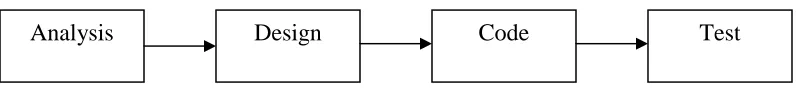
2.3.1 The Waterfall Model
The Waterfall Model suggests a sequential and systematic approach to software
development. The classical model consists of the following main phases: Analysis, Design, Implementation, Testing, Maintenance [7].
Here the maintenance phase is not included because the concentration of this thesis is on
Figure 1: Classical Waterfall Model
• Analysis: Requirements related to the software being developed are gathered
during this phase. After this, the project team prepares a document, which outlines
the required function, performance, interfaces, etc. This document is reviewed by the developers and the customer.
• Design: In this phase, the requirements finalized during the previous phase are
translated and documented into a representation of the software. This
representation focuses on data structure, software architecture, interface representations and algorithmic details. Design documents are prepared by the
developers, which can be evaluated for quality.
• Implementation: The design is translated into a machine-readable form through
code generation. Good design documents result in easier implementation.
• Testing: This phase focuses on detecting and correcting errors in the functional
externals and logical internals of the software that is developed in the previous phase. The functional externals are tested in order to ensure that certain inputs will produce the required outputs. The logical internals are tested in order to
ensure that all possible paths within the code are logically correct.
The "waterfall model", documented in 1970 by Royce was the first publicly documented life cycle model. The model was developed to help cope with the increasing
complexity of aerospace products. The waterfall model followed a documentation driven paradigm. Some variants of the Waterfall model are as follows:
• Simple Waterfall model: Sequential and document driven.
• Waterfall model using the build-it-twice rule (incremental development): The
build-it-twice rule enables developers to build a prototype in order to explore potential difficulties or to obtain an idea of the customer’s requirements.
• Waterfall model with phase to phase feedback loops (Figure 2): Feedback loops
enable developers to evaluate the work done at the end of a phase and provide an
option of going back to the previous phase if any changes are required. The original model proposed by Winston Royce made provisions for phase to phase
feedback loops [14]. However, most organizations that use this model consider it to be strictly sequential. Verification is a process which ensures that the
developed software implements a specific function correctly, whereas validation
is a process which ensures that the developed software is traceable to customer requirements [7]. Some of the activities that are encompassed by verification and
validation are formal technical reviews, testing, inspections, evaluations, etc. In the figure below, validation is done at the level of system feasibility and software plans and requirements in the form of reviews. Verification is done at the level of
System Feasibility
Validation
Software plans and requirements
Validation
Product Design
Verification
Detailed Design
Verification
Code
Unit Test
Integration
Product Verification
Implementation
System Test
Operations and Maintenance
Revalidation
Advantages:
1. It provides a template into which methods for the different phases can be placed.
2. It is better than using an approach without any structure and it also provides a basis for other models.
Disadvantages:
1. The model proposes a sequential flow, which real projects rarely follow [15]. It indirectly accommodates iterations and hence, changes can cause confusion.
2. The model requires that all requirements be stated explicitly at the beginning, which might not always be possible. Changes to requirements cannot be easily
accommodated.
3. It takes a long time to create a working version of the software and hence, if a major blunder goes undetected till the working version is reviewed, it can be
extremely disastrous.
4. The linear nature of the model may cause some project members to wait until the
other members finish dependent tasks.
5. It requires the completion of detailed documents. While this criterion is good for products that can easily be formalized, such as compilers, it does not work well
for end-user applications. Since the uses and interfaces of end-user applications are often poorly understood by software developers at the beginning of a project,
writing the specifications in great detail is often futile.
In spite of the various problems that are encountered when this model is applied, it is a reasonable approach when the requirements are well understood. The Waterfall
the areas of user interface and performance requirements, but high risk in budget and schedule predictability and control. The pure waterfall performs well for products with
clearly understood requirements or when working with well understood technical tools, architectures and infrastructures. Its weaknesses frequently make it unadvisable when
rapid development is needed. In those cases, modified models may be more effective. The Waterfall model is not useful for user-interactive systems; projects involving extensive software reuse; projects involving high risk elements; changing requirements.
The Modified Waterfall Model (Classical waterfall model modified with feedback at every stage) is used mainly in embedded real time systems projects.
2.3.2 The Spiral Model
The Spiral Model is an evolutionary model that combines the iterative nature of prototyping with the systematic approach of the Waterfall model [16, 17]. It ends each
Waterfall Model phase with risk assessment and prototyping [18 – 20]. Thus, it captures the evolutionary nature of software. Each iteration gives rise to a prototype, which is a working version of the software; however, the complete and final version will be
produced only after an adequate number of iterations [21, 22]. Each prototype is used to determine whether the project should be continued, stopped or sent back through the
previous phases. Software development is in the form of incremental releases. The model consists of the following six framework activities or task regions:
Customer Communication; Planning; Risk Analysis; Engineering; Construction and
Each cycle is completed by a review of the software involving the primary people concerned with it.
• Customer Communication: This phase consists of tasks that establish effective
communication between the developer and the customer.
• Planning: This phase consists of tasks that define resources, timelines and other
information related to the project at hand.
• Risk Analysis: This phase consists of tasks that assess technical and management
risks.
• Engineering: This phase consists of tasks that build representations of the
software.
• Construction and Release: This phase consists of tasks that construct, test, install
software and provide support to the customer.
• Customer Evaluation: This phase consists of tasks that obtain customer feedback
of the evaluation of the software representations created during the Engineering phase and installed during the Construction and Release phase.
The project team begins in the center and moves around the spiral in a clockwise
direction as the project proceeds. Adjustments are made to the project plan in each pass through the Planning phase. Based on the feedback obtained from the Customer Evaluation phase, the cost and schedule are adjusted. Also, the planned number of
iterations required for completion of the project is also adjusted. Requirements validation is done in the second loop of the spiral and design validation is done in the third.
Figure 3: The Spiral Model [16]
Advantages:
1. The model creates a risk-driven approach rather than a document-driven or code-driven one.
2. At each evolutionary level, the developer and customer better understand and
react to risks since the software evolves as the process progresses.
3. It maintains the systematic approach advocated by the Waterfall model and
incorporates it into an iterative framework that is more realistic.
4. At all stages, it demands a direct consideration of technical risks and hence, can be used to reduce risks.
2. Problems will definitely occur if a major risk is not detected and managed. 3. The processes are still linear.
4. In some cases, convincing customers that the evolutionary approach is controllable requires some effort.
5. It assumes that the development processes will produce predictable results.
The Spiral model is useful for projects involving high risk elements; large and complex projects. For projects with risky elements, it's beneficial to run a series of
risk-reduction iterations which can be followed by a waterfall or other non-risk-based lifecycle. The Spiral Model with rapid prototyping is used mainly in GUI intensive
projects and web based Internet related product development.
2.3.3 The Rational Unified Process (RUP)
The Rational Unified Process is developed and maintained by Rational Software.
It consists of the following fundamental workflows:
1. Business Engineering: Obtaining the requirements of the business.
2. Requirements: Converting business needs into automated system behavior.
3. Analysis and Design: Converting requirements into software architecture.
4. Implementation: Creating software with the architecture that has the required
behavior.
5. Test: Ensuring that all the required behaviors of the software are present and are correct.
7. Project Management: Managing all the resources and schedules.
8. Environment: Setting up and the maintaining the development environment.
9. Deployment: Managing the things required for rollout and installation of the software.
All these activities are executed concurrently throughout the project lifecycle. The RUP project consists of the following phases:
Inception, Elaboration, Construction, Transition [23]
• Inception: This phase determines the objectives of the project. Different solutions
and architectures are explored during the course of iterations to measure how
quickly the iterations can be done so that a schedule can be created. A requirements document or a preliminary project plan could be the result of this
phase. It delineates what software is to be built and what value it provides to users.
Life Cycle Objective Milestone: This is reached when the developers and the customer agree upon a preliminary schedule of iterations, architecture and planned objectives. It marks the end of the Inception phase and the beginning of
the Elaboration phase.
• Elaboration: This phase establishes a firm understanding of the problem. The
architectural foundation of the software is established, a detailed plan is made, the process is refined and high risks are eliminated. New features and tests are added to the software during iterations and technical feasibility is demonstrated.
Life Cycle Architecture Milestone: This is reached when it has been agreed that the major risks have been addressed, the chosen architecture will scale to support
the full development and the project plan is achievable. It marks the end of the Elaboration phase and the beginning of the Construction phase.
• Construction: After building software, at the end of the iteration, a working
version is delivered to the customer. This phase is similar to the previous phase.
Also, use cases are added to the software during the iterations. Verification is done during this step in the form of integration tests.
Initial Operational Capability Milestone: This is crossed when the software provides some useful value and is stable enough to be used. It marks the end of the Construction phase and the beginning of the Transition phase.
• Transition: In this phase, the features that are being used by the users actively are
added to the software. A discussion of the length of the upgrade cycle also takes
place between the developers and customers. It is similar to the Construction phase. The system is simply enhanced and improved to meet the planned objectives. Also, software is prepared for deployment and documentation, and
training facilities and support are developed.
Figure 4: Typical Iteration Flow [24]
Figure 5: Phases and Iterations of RUP [24]
Advantages:
1. RUP is an iterative and disciplined approach in which risks are identified and mitigated early. Change is more manageable and a high level of reuse is present.
Requirements
Analysis & Design
Implementation Deployment Test Evaluation Business Modeling Planning Initial Planning
Inception Elaboration Construction Transition
Initial Trans # 1 Trans # 2 Cons t # 2 Const # 2 Cons t # 1 Elab # 2 Elab # 1 Business Modeling
Analysis & Design
Requirements
Implementation
Test
Deployment Disciplines
Config & Chng Mgmt.
Project Mgmt.
3. The main objective of RUP is risk mitigation.
4. The project team gains knowledge as the project proceeds.
5. It is a use-case driven process in which effective use-cases are used to drive development of the design and tests. Requirements are easily decomposed into
manageable chunks. Disadvantages:
1. RUP is considered to be a heavyweight methodology.
2. It is a generic process and needs to be customized before use.
RUP works well with cross-functional projects [25]. Also, due to its flexible
design, it is applicable to large e-business transformation projects [26]. RUP is not useful for maintenance type projects.
2.3.4 Extreme Programming (XP)
Extreme Programming is a software development discipline that is based upon the four values of communication, simplicity, feedback and courage [27]. It encourages communication between customers and developers by having an on-site customer during
development. Simplicity is incorporated by continuous refactoring of code and producing a minimal set of non-code artifacts. Feedback is provided by numerous short releases and
unit tests. Courage means being honest and realistic about the things that can and cannot be done. These four values are supported by the following twelve practices:
1. The Planning Game: Through a combination of technical estimates and prioritized
done throughout the process since there is always a customer on-site to ensure that the system is being development according to the requirements.
2. Small Releases: Small incremental versions of the software are released to the customer.
3. Metaphor: It is a description of the working of the system.
4. Simple Design: The design and code are kept simple by continually eliminating the complexity in the code.
5. Testing: It encourages test-driven development which means that the tests are written before the code is implemented.
6. Refactoring: This is a technique that removes duplication and complexity from the code.
7. Pair Programming: Two programmers develop code at a single computer. One
programmer, called the driver, writes the code and another programmer, called the navigator, reviews it at the same time. They interchange roles periodically.
8. Collective Ownership: Everyone has the ability to change any part of the code at any time.
9. Continuous Integration: The software is built and integrated several times a day
after the completion of every implementation task. Verification is done during this step.
10. Forty-hour Week: Overtime is never allowed for two consecutive weeks because it is believed that programmers cannot be efficient when they are tired.
12. Coding Standards: A consistent coding standard is adopted by the developers.
Advantages:
1. It is considered to be a lightweight and fast methodology, which is used to build
systems very quickly.
2. Software is created by pairs of developers and is tested continuously; hence, the quality of the source code is high.
3. Since the program design is simple and extensible, the costs are lower. 4. Customer requirements can be incorporated at any stage of development.
5. It is good for projects that have short schedules, those that are time critical, those that do not have well-defined user requirements, those that need to be reliable or those that need schedule visibility.
6. The practice of pair-programming ensures that at least two persons are familiar with the code.
Disadvantages:
1. XP is not very useful if users have a firm idea of their requirements.
2. Also, it will not be useful if system requirements will not be expected to change
frequently.
3. Very little time is spent in the design phase and this can cause problems, since
reorganizing code could be difficult and time consuming.
5. It is considered to be too code-centric and would appeal to developers who do not consider upstream development activities to be useful.
6. Some practices like pair-programming, collective code ownership, continuous integration could conflict with some management styles and some developers’
work patterns.
7. For pair-programming to be successful, programmers need to get along well and also, need to have similar technical skills.
XP is useful for projects that have low risk in areas such as losing budget, schedule predictability and control, large-system integration problems, but high risk in
user interface design.
2.4 Selecting an appropriate Software Process Model
According to various studies conducted and data collected by Barry Boehm [3], it has been concluded that the relative costs to detect and correct errors in the later stages of
a software development life cycle are much more than those in the initial stages. Hence, selecting an appropriate software process model is an extremely important task.
Every process consists of basic elements such as Analysis, Design, Implementation, Testing, Verification and Validation. However, the order and granularity of these elements are different depending on different processes. These elements need to
• Identification of the process model alternatives,
• Identification of the constraints imposed on the application of the alternatives,
• Evaluation of the process model alternatives relative to the objectives and
constraints,
• Risk identification, and
• Risk analysis.
Barry Boehm has provided the above mentioned method and also a Process
3. THE KNOWLEDGE INSIGHT MODEL
(KIM)
3.1 Overview of KIM
Organizations consist of people who create and manage knowledge in order to execute processes that are required for the organization's growth and survival. These
processes depend on how knowledge is created, acquired, shared, synthesized, packaged, archived, transferred and used. The Knowledge Insight Model (KIM) is used for knowledge management. It provides a framework with a set of related models, namely,
the Framer, the Maker, the Sharer and the Finder and is a source of a holistic dynamic model [5]. It can also be used for managing Information Technology investments and for measuring the returns on these investments. KIM was developed from the Information
Technology Management Model (ITMM) [29], which provides a framework for an organization to analyze its current position and work through a continuous improvement
cycle as advocated by Kaizen [30], which is a Japanese term meaning “continuous improvement process”. It also comprises of Hoshin [31], which is a Japanese term meaning “innovation or breakthrough process”. Hoshin and Kaizen are a part of Total
Quality Management (TQM), whose principles encourage continuous improvement [32, 33]. There are two concepts involved in understanding the KIM, namely, External and
3.2 External & Internal Discover & Refine
A system is exposed to various external factors and internal components ranging from immediate surroundings to a more general environment. The external environment
includes skilled professionals, methods used for development, technologies and tools used for implementation, competition, time, financial aspects, etc. The internal environment includes features, complexity, availability of reusable modules, etc. These
external and internal factors affect a system's performance and are also dynamic in nature. They change and evolve over time and thus, are not static entities. Processes
depend on both the internal as well as the external environments and are initially discovered and later refined. They iterate between discover and refine stages until a satisfactory solution is found for the problem at hand. The combination of all these
concepts gives rise to the following four-quadrant matrix:
Table 1: Four Quadrant Matrix [5]
Internal Discover External Discover Internal Refine External Refine
In the above matrix, transitions from one state into the other involve iterations and cycles. The transition from the discover phase to the refine phase represents solution
increment, whereas that from the refine phase to the discover phase represents consolidation [5]. These transitions can be iterated any number of times until the desired
depend on the amount of creativity achieved. The output obtained could also be used as feedback and the process could be iterated until a mature solution is obtained.
3.3 PDCA Cycle
The Plan-Do-Check-Act cycle is a checklist of activities to be performed in order to solve a general problem [34]. The explanation of each stage is as follows:
Plan – Identify the problems involved.
Do – Develop a design to solve the problems on a small or experimental scale.
Check – Analyze the results and determine whether the desired result is achieved or not. Act – Implement the changes on a larger scale if the experiment on the smaller scale was successful.
The outcome of each PDCA cycle can be fed into the Plan stage of some related PDCA cycle or for solving new problems that may also include refinement, but if the
experiment on the smaller scale fails, the Act stage can be skipped and the cycle can be started again by going into the Plan stage.
3.4 The Knowledge Insight Model
The Knowledge Insight Model (KIM) provides a framework to manage
knowledge. It consists of a continuous process of discovery and refinement, which repeatedly builds on itself [5]. This means that discovery leads to refinement and
Finder, which focus on the 4 basic functions of Plan, Do, Check and Act respectively, of the 2 PDCA problem solving cycles that support KIM.
From the perspective of knowledge management, KIM represents a higher abstraction for capturing knowledge in its purest form for any process. KIM can be used
not only to capture existing knowledge, but also to plan for the creation, sharing and deployment of new knowledge. The next few sections describe in detail, the four models that constitute the KIM.
The above figure shows the various components of the Knowledge Insight Model. If the figure is divided into four quadrants, the four-quadrant matrix (Table 1) will be
obtained. The diagonal line that runs through External Discover 1, External Discover 2, External Refine 1
k Internal Discover 1
H
Internal Discover 2 h
External Discover 1
External Discover 2
Internal Refine 1
Internal Refine 2 External Refine 2
K Maturity Consolidate Learning Consolidate Innovation Solution Inc re me nt Solution Inc re me nt Rationalization
Internal Refine 1 and Internal Refine 2 is called the Seam. Every stage represents one of the P, D, C or A activities of the PDCA cycle.
3.4.1 Framer
The Framer offers a “big picture” view, so that adequate planning may be done in
order to solve a problem. It is a role, which is associated with the Plan phase of the PDCA cycle and the “Hoshin” concept, which is the Japanese term for breakthrough. The
Framer tries to understand the external and internal environments, the requirements and the interfacing that is required within the two. Based on this information, he tries to put together a plan of action or a strategy and comes up with a framework for developing the
product or solution from its discovery to its refinement. In case of ideas or concepts, External Discover 1
External Refine 2 Innovation
Consolidate
Maturity Internal Discover 1
Internal Refine 1 Internal Refine 2
Solution
Inc
re
me
nt
thinks of a strategy to refine the development process. Thus, from an organization’s perspective, the Framer is used to define strategies, activities, tasks, etc. that are required
in order to achieve the organization’s goals.
The Framer consists of the following steps:
External Discover 1, Innovation, Internal Discover 1, Solution Increment, Internal Refine 1, Internal Refine 2, Maturity, External Refine 2, Consolidate.
Thus, the Framer forms the outer loop of steps in the KIM diagram. In addition to
this, a Framer also has his separate PDCA cycle, in which he carries out the following functions:
Plan – understand the environment and define the problem. Do – develop a plan.
Check – analyze the plan and verify whether it satisfies the requirements.
3.4.2 Maker
The Maker is a role that is associated with the Do phase in the PDCA cycle. It can
also be associated with Hoshin, since it is used to create new products, processes, concepts, etc. Based on the plan formulated by the Framer, the Maker creates a design that can be implemented by the Finder. The Maker always performs his functions before
the Finder can take over and works in tandem with the Finder. Thus, the Maker is used to define the ways in which existing knowledge can be combined to meet the planned
objectives and also to determine new ones.
The Maker consists of the following steps:
External Discover 1, Innovation, Internal Discover 1, Solution Increment, Internal Refine
1, Consolidate, Internal Discover 2.
External Discover 1
Internal Refine 2
Innovation
Solution
Inc
re
me
nt
Internal Discover 1
Internal Discover 2
Consolidate
Thus, the Maker forms the triangle of steps above the seam or the upper triangle in the KIM diagram. In addition to this, a Maker also has his separate PDCA cycle, in
which he carries out the following functions: Plan – analyze the Framer's plan.
Do – scan existing knowledge and also create some new knowledge.
Check – evaluate the available knowledge and verify its compatibility with the new knowledge.
Act – develop a design to implement the plan incorporating all the available and newly created knowledge.
3.4.3 Sharer
External Refine 1 Internal Refine 1
Internal Refine 2
External Discover 2 Internal Discover 2
Consolidate
Solution
Inc
re
me
nt
Rationalization Learning
Every organization contains a knowledge base, which is a pool of knowledge comprising of the knowledge accumulated over the years. This has to be updated to reflect changes
and maintained to retain useful information. This is done by the Sharer, which is a role that is associated with the Check phase in the PDCA cycle. This starts off with checking
and is the only one of the four roles that goes in the clockwise direction. It ensures that the Maker and the Finder work in tandem with each other. Thus, the Sharer is used to define the ways in which knowledge can be tracked, monitored, created and delivered.
The Sharer consists of the following steps:
External Discover 2, Solution Increment, External Refine 1, Rationalization, Internal
Refine 2, Internal Refine 1, Consolidate, Internal Discover 2, Learning.
Thus, the Sharer forms the inner loop of steps in the KIM diagram. In addition to this, a Sharer also has his separate PDCA cycle, in which he carries out the following
functions:
Check – track, verify and monitor existing knowledge.
Act – process and package knowledge.
Plan – decide the course of action in accordance with the Framer's plan and the Maker's design.
Do – acquire new knowledge if required and available externally, or create it internally. Check – add new knowledge to the knowledge base.
Maker and the Finder cannot function at the same time due to the nature of their respective functions.
3.4.4 Finder
The Finder is a role that is associated with the Act phase in the PDCA cycle. It
can also be associated with Kaizen, since it encourages continuous improvements. It is used to provide feedback to the next phase of development by evaluating the results of the previous phase. Thus, the Finder is used to define the ways in which internal
knowledge can be completed with external knowledge and utilized to meet the defined objectives as well as to create new ones.
The Finder consists of the following steps:
External Refine 1
Internal Refine 2 External Refine 2
Maturity
External Discover 2
S
o
lu
ti
o
n
In
cr
em
en
t
Rationalization
External Discover 2, Solution Increment, External Refine 1, Rationalization, Internal Refine 2, Maturity, External Refine 2.
Thus, the Finder forms the triangle of steps below the seam or the lower triangle in the KIM diagram. In addition to this, a Finder also has his separate PDCA cycle, in
which he carries out the following functions:
Plan – refine and extend the Framer's plan to find internally missing knowledge. Do – deploy the available knowledge and seek missing knowledge.
Check – evaluate the results of deployment and check for compatibility between the new and the existing knowledge.
Act – aggregate knowledge clusters in order to improve deployment.
A summary of functions of the four roles would be
Framer: Management Maker: Discovery
Finder: Transfer Sharer: Rationalization
3.5 Switching
The Knowledge Insight model could be visualized as containing four modes, namely, the Framer, the Maker, the Sharer and the Finder. Switching from one mode to another is simple, fast and easy and could depict a normal workflow during the process of
from the Maker mode to the Sharer mode (at a higher level of abstraction) would mean doing a review of the design created by the Maker (at a lower level of abstraction). These
switches are explained more in detail in the following sections with the help of diagrams. Four types of switches are possible, as can be observed from the following list:
1. Framer to Maker 2. Framer to Finder 3. Sharer to Maker
4. Sharer to Finder
This switching is only possible according to the Markov Chain Representation of the
KIM (Figure 15).
3.5.1 Framer to Maker and vice versa
Figure 11: Framer to Maker and vice versa
External Discover 1
Internal Refine 1 External Refine 2
Innovation
Consolidate
Solution
Inc
re
me
nt
Maturity Internal Discover 1
External Discover 2 Internal Discover 2
Learning
Consolidate
A switch from the Framer mode to the Maker mode would constitute a normal sequence of operations in the software development process and would typically
represent a transition from the planning or requirements gathering phase to the design phase of a project. This would be required only in case of absence of useful off-the-shelf
or reusable components and if some components need to be designed and implemented for the project to proceed.
A switch from the Maker mode to the Framer mode would depict the backward
flow from the design phase to the planning phase so as to accommodate a few late changes in the requirements specification. After the desired changes to the requirements
have been made, there would be a switch back from the Framer to the Maker in order to reflect the new changes in the design.
3.5.2 Framer to Finder and vice versa
Innovation Internal Discover 1
Solution
Inc
re
me
nt
External Refine 1
External Discover 1
External Refine 2
Consolidate
Maturity
External Discover 2
Solution
Increm
ent
Rationalization Internal Refine 1
A switch from the Framer mode to the Finder mode could imply that reusable or
off-the-shelf components are available for use and hence no design step needs to be present. It could also delineate a return of control from a change in the overall plan to the
coding phase, so as to implement the changes in the software developed so far. During normal circumstances, a change in the plan would first result in a change in the design and later, a change in the implementation.
A switch from the Finder mode to the Framer mode represents a feedback from the implementation phase to the planning phase, in case of new additions or
improvements to the plan after the design, implementation and testing of the initial plan. Hence, this switch could take place in case of success or failure of the initial plan.
3.5.3 Sharer to Maker and vice versa
External Refine 1 Internal Refine 1
External Discover 1
Internal Refine 2
Innovation Internal Discover 1
External Discover 2 Internal Discover 2
Solution
Inc
re
me
nt
Consolidate
Solution
Inc
re
me
nt
A switch from the Sharer mode to the Maker mode would represent a transition from the testing phase to the design phase in case of faults or defects in the design that
has been prepared by the team. This switch can also take place in case of failure of a test after implementation, which necessitates a change in the design of the software being
developed.
A switch from the Maker mode to the Sharer mode would represent a design review taking place in order to prevent any undesirable elements or logic in the design of
the software itself. This is a necessary step for a better design and also for avoiding changes to the design after the implementation.
3.5.4 Sharer to Finder and vice versa
External Refine 1 Internal Refine 1
External Discover 1
Internal Refine 2 External Refine 2
Consolidate
Maturity
External Discover 2 Internal Discover 2
Consolidate
Solution
Inc
re
me
nt
Rationalization Learning
A switch from the Sharer mode to the Finder mode would be a result of test failure, which would necessitate changes in the implementation of the software being
developed. Also, it could represent the next step for implementing additional modules after the successful testing of the previous ones.
A switch from the Finder mode to the Sharer mode represents the beginning of the testing phase after the coding is over. Thus, this is a part of the normal sequence of
operations in the development of software.
3.6 Markov Chain Representation of KIM
A Markov chain [35] is a discrete-time process, such that, given the past and the present stages, the probability of an outcome in the future stage only depends on the
present stage and not the past. The probabilities are entered in a Transition Matrix. A Markov process [36] is the continuous-time version of a Markov chain, but the transition
behavior is different. In a Markov process, transitions take place at random points in time. That is, the Transition Matrix in a Markov Chain remains the same, but that in a Markov Process changes during every trial. Markov chains and processes are used to
make predictions about the situation being modeled.
h
K k
H maker
finder
sharer framer
In the above figure, H: External Hoshin
K: External Kaizen h: Internal Hoshin
k: Internal Kaizen
F: External Forward Flow B: External Backward Flow
f: Internal Forward Flow b: Internal Backward Flow
The KIM is modeled as a Markov process because the Transition Matrix changes during every trial.
The rows represent the ‘from’ states and the columns represent the ‘to’ states.
Table 2: Transition Matrix [5]
H h k K
H - MAKER - FRAMER
h maker - SHARER
-k - sharer - FINDER
-probabilities of being in particular roles. They also represent transitions from one state to another, e.g., the MAKER represents a transition from H to h.
The Framer represents a transition from H to K and vice versa. The Maker represents a transition from H to h and vice versa. The Sharer represents a transition from
h to k (inner mechanism). The Finder represents a transition from k to K and vice versa. The forward flow is the normal flow of the development process and the transitions can be as follows:
H --> h --> k --> K
The backward flow represents some anomaly in the normal flow of the
development process in the form of errors, defects, etc. The transitions can be as follows: K --> k --> h -->H
The following table is a simplified form of the Transition Matrix (Table 2).
Table 3: Transitions in Forward Flow
Pattern Transition in Forward Flow FRAMER H --> K
MAKER H --> h
SHARER h --> k FINDER k --> K
Table 4: Transitions in Backward Flow
Pattern Transition in Backward Flow framer K --> H
maker h --> H
sharer k --> h finder K --> k
In the beginning of the project, there could be a large number of possibilities or
knowledge could be slow and steady in the implementation phase. A normal forward flow would be from the Maker to the Finder, whereas a backward flow would be in the
opposite direction, i.e., from the Finder to the Maker. A backward flow would be possible only if the design requires changes after implementation for correction or additional
functionality.
3.7 KIM Example 1
The following example shows how the KIM can be used as a guide for reporting
exploration information:
External Discover 1(PLAN1): Evaluation criteria: General (Purpose of report, Project description, Project Location, Property Ownership):
This involves obtaining the statement of the person for whom the report was prepared, description of the commodity, magnitude of the project, background, business
arrangements, description of the location, description of ownership of surface rights, mineral rights, access rights, leases, concessions, royalties and other liabilities.
Internal Discover 1(DO1): Evaluation criteria: Project data (Location of project data, Geological data, Sampling, Analysis, Specific gravity and Bulk Tonnage):
This involves creating maps, cross-sections, other 2D or 3D representations of information showing location of samples, drill holes, exploration pits, underground
recorded, description of sample type, sample collection method, discussion of sample quality, quantity and verification techniques.
Internal Refine 1(CHECK1): Evaluation criteria: Interpretation (Geological Interpretation and Model, Numerical Model):
This includes the description of the geological model and inferences made from it, detailed description of the method used and assumptions made to estimate tonnages and
grades, a description of how the geological interpretation was used to control the resource estimates, description of the programs and parameters used if a computer method was
chosen, description of the geo-statistical methods used and their compatibility with the geological interpretation.
Internal Discover 2(ACT1): Evaluation criteria: Extraction (Mining, Processing, Recovery, Environmental Compliance and Reclamation, Cutoff Grade):
This involves a description of obvious mining, processing, environmental factors that could have a significant impact on project feasibility, the description and justification of operating costs, mining dilution, losses, processing recoveries, the description of
environmental compliance methods, costs and the description of methods used in calculating cut-off grades.
This includes a description of valuable and potentially valuable product(s), the suitability of products to the market and the detailed description of the method used to
determine economic feasibility of the project.
External Refine 1(DO2): Evaluation criteria: Assurance Classification:
This involves a description and justification of criteria used to classify a resource (measured, indicated or inferred) or reserve (proven or probable).
Internal Refine 2(CHECK2): Evaluation criteria: Other considerations:
This includes a description of any other significant information that would prevent or facilitate the economic viability of the project. Also, there should be a
reasonable basis to believe that permitting and constructing the necessary facilities can be
accomplished in a timely manner.
External Refine 2(ACT2): Qualification of Estimator(s):
The person(s) preparing and reviewing the report should be competent, well qualified and should have the ability to take the appropriate decision.
3.8 KIM Example 2
Plan 1: Make a list of the requirements which includes the type of implementation
required (in this case, linked list), language to be used for coding, amount of time allotted
for the implementation, etc.
Do 1: Create a design taking all the requirements into consideration. This design will
contain data structures and prototypes of the functions required (in this case, push and pop).
Check 1(Validation): Review the design to check whether all the requirements are being
met.
Act 1: Implement the design by coding.
Plan 2: Compare with the design documents to check for completion or enhancements. Do 2: Make the required changes.
Check 2 (Verification): Test the implementation.
Act 2: Validate the implementation by comparing with the requirements specification. Make the implementation ready for submission by creating a Readme file with
4. KIM - A SOFTWARE PROCESS MODEL
4.1 KIM as a Software Process Model
The Knowledge Insight Model (KIM) has been used as a model for Knowledge Management. However, it can be used as a model for Software Development. This is due
to the following reasons:
• It describes an iterative process,
• It represents a higher level of abstraction of some software development models
(this will be elaborated later in this chapter),
• It implements separation of duties, organized activity and modularity very
effectively,
• It symbolizes a unique trend of forward and backward flows during the course of
development, and
• It is very flexible and easy to model in various different, yet completely organized
ways.
The Knowledge Insight approach uses the Knowledge Insight Model to bring
order to the chaos involved in the process of developing software. This approach can be used in the following 3 circumstances:
• To develop software from scratch,
• To reuse available components, and
Software development is a complex task and has to take place under certain circumstances that may undergo various changes. The Knowledge Insight Approach
makes the following assumptions:
• The requirements, design, implementation and tests are incomplete,
• The outcome is unpredictable at the beginning.
• As development proceeds, due to the application of control mechanisms, the risks
and unpredictability can be managed.
Requirements are often incompletely defined or they change as development proceeds. Evolutionary models are iterative and are designed to accommodate a product that evolves over a period of time. KIM takes the evolutionary nature of projects into
account. KIM can be tailored to suit specific requirements of an organization. Since the KIM is very flexible, it has a high degree of tolerance to changes during the course of a
project.
4.2 A Software Process using KIM
KIM can be used for the development of small, medium as well as large sized
software projects. For small projects, a shorter and quicker process with less formality can be used. For larger projects, a more detailed version of the process can be used. The software process is explained more in detail in the next few sections. In addition to this, it
4.2.1 A Software Process for Small Projects using KIM
The following steps are required for the development of small software projects:
STEP 1: External Discover 1ÿÿÿÿPlan 1
This step involves the formulation of an idea. The term “Hoshin”, which means breakthrough in Japanese, can be used for describing it. A plan of action is put together by understanding the external environment, internal requirements and the interfacing
required between the two. Also, risk analysis can be done in this phase. The Framer, who is associated with the Plan phase of the PDCA cycle, is responsible for formulating a
plan.
External Refine 1 k (Do 2)
Internal Discover 1 H (Do 1)
Internal Discover 2 h (Act 1)
External Discover 1 (Plan 1) External Discover 2
(Plan 2)
Internal Refine 1 (Check 1) Internal Refine 2
(Check 2)
External Refine 2 K (Act 2) Maturity Consolidate Learning Consolidate Innovation Solution Inc re me nt Solution Inc re me nt Rationalization
It means the intent to adapt the concept or idea to the problem area and carry out some sort of analysis of the problem.
STEP 2: Internal Discover 1ÿÿÿÿDo 1
At this stage, the concept of a solution needs to be developed. This could be done
by creating a broader plan and/or a knowledge base to aid in making decisions. Information is collected for analyzing the problem and modeling the specifics of the development process to formulate and initiate an implementation plan. The Maker, who
is associated with the Do phase of the PDCA cycle, is responsible for carrying out the activities in this phase.
Transition 2: Solution Increment (transition between logical/planning view and process/implementation view)
This explains how to develop a plan for tackling the problem at hand.
STEP 3: Internal Refine 1ÿÿÿÿCheck 1 (Validation)
This step deals with the analysis of the implementation plan and understanding
requirements of the implementation process. Steps are taken to understand the manner in which information can be circulated for implementation. The solution is validated and the risks identified in the External Discover 1 phase are assessed in order to check whether
they have been eliminated. Validation is the set of activities that ensure that the software that has been developed is according to the requirements specified by the customer. It is
used for answering the question “Are we building the right product?” [7] The Sharer, who is associated with the Check phase of the PDCA cycle, is responsible for validating the solution. Monitoring and controlling changes is very important and is done by the
Transition 3: Consolidate (transition between logical/planning view and process/implementation view)
After implementing the plan, one has to consolidate towards specific details of the problem.
STEP 4: Internal Discover 2ÿÿÿÿAct 1
This deals with testing the solution to check whether it is applicable to the problem area or not. The Finder, who is associated with the Act phase of the PDCA
cycle, is responsible for giving shape and form (product/solution) to the Maker’s implementation plan.
Transition 4: Learning (transition between knowledge base and solution areas)
This deals with understanding the kind of solution produced and how it can be applied to the problem at hand.
STEP 5: External Discover 2ÿÿÿÿPlan 2
This involves testing the solution with data from the problem area to see if the
solution and adaptation are complete. Thus, the product or solution is reanalyzed and external situations are once again verified with the internal solutions being developed. If the solution is inapplicable or if the tests produce undesirable results, then newer ideas
have to be developed. The Framer, who is associated with the Plan phase of the PDCA cycle, is responsible for designing a framework for proceeding ahead.
Transition 5: Solution Increment (transition between logical/planning view and process/implementation view)
STEP 6: External Refine 1ÿÿÿÿDo 2
This deals with the refinement of the solution. The product is analyzed for
implementation specific details. The analysis should also confirm that all the required functionality is achieved and that the product is fail-safe. The Maker, who is associated
with the Do phase of the PDCA cycle, is responsible for the tasks to be performed in this phase.
Transition 6: Rationalization (transition between knowledge base and solution areas) This identifies the areas, which need to be touched up, and those that need to be finalized.
STEP 7: Internal Refine 2ÿÿÿÿCheck 2 (Verification)
This deals with perfecting the solution so that it always solves the problem and doesn’t fail in any situation. Verification refers to the set of activities that ensure that the
software correctly implements the required functions. It is used for answering the
question “Are we building the product right?” [7] The Sharer, who is associated with the
Check phase of the PDCA cycle, is responsible for checking the final product for any possible errors.
Transition 7: Maturity (transition between knowledge base and solution areas)
In this, the product which is developed and refined needs to be packaged as a product or applied to the problem on a broader scale.
STEP 8: External Refine 2ÿÿÿÿAct 2
installation should take place, is planned and carried out by the Finder, who is associated with the Act phase of the PDCA cycle.
Transition 8: Consolidate (transition between logical/planning view and process/implementation view)
If the solution fails, another solution has to be formulated. If a better solution that covers a broader area is required, the 8-step process can be repeated any number of times.
4.2.2 A Software Process for Medium to Large sized Projects using KIM
The software process that uses KIM for medium to large sized projects is shown
in the figure above. This figure has been developed according to the Markov Chain Representation of the KIM, which has been explained in Chapter 3. For medium and
Maker
Sharer Framer
Finder
additional phases and a greater amount of formality as compared to the one used for small projects. The software process for medium to large sized projects consists of the
following order of steps: • Framer
• Maker
• Sharer
• Finder
After these steps, the next one could be Sharer (if the software needs to be tested again) or Framer (if the next iteration needs to be commenced). A switch from one step to
the next can be done according to the switching described in Chapter 3.
Framer:
The objective of the Framer stage is to analyze the feasibility of the project. This is done by analyzing and documenting the goals and risks. In addition to this, an outline
![Figure 2: Waterfall Model Variant [14]](https://thumb-us.123doks.com/thumbv2/123dok_us/1709979.1217338/21.612.87.508.60.628/figure-waterfall-model-variant.webp)
![Figure 3: The Spiral Model [16]](https://thumb-us.123doks.com/thumbv2/123dok_us/1709979.1217338/25.612.94.502.75.343/figure-the-spiral-model.webp)
![Figure 4: Typical Iteration Flow [24]](https://thumb-us.123doks.com/thumbv2/123dok_us/1709979.1217338/29.612.75.546.281.531/figure-typical-iteration-flow.webp)
![Figure 6: The Knowledge Insight Model [5]](https://thumb-us.123doks.com/thumbv2/123dok_us/1709979.1217338/38.612.87.526.272.599/figure-the-knowledge-insight-model.webp)
![Figure 7: Framer [5]](https://thumb-us.123doks.com/thumbv2/123dok_us/1709979.1217338/39.612.79.543.176.447/figure-framer.webp)
![Figure 8: Maker [5]](https://thumb-us.123doks.com/thumbv2/123dok_us/1709979.1217338/41.612.93.526.92.381/figure-maker.webp)
![Figure 9: Sharer [5]](https://thumb-us.123doks.com/thumbv2/123dok_us/1709979.1217338/42.612.65.471.414.679/figure-sharer.webp)
![Figure 10: Finder [5]](https://thumb-us.123doks.com/thumbv2/123dok_us/1709979.1217338/44.612.79.520.153.461/figure-finder.webp)

