Volume 5, No. 7, September-October 2014
International Journal of Advanced Research in Computer Science
REVIEW ARTICAL
Available Online at www.ijarcs.info
ISSN No. 0976-5697
Multi Focus Image Fusion Using Discrete Wavelet Transform Algorithm
M.Mohamed Suhail
Research Scholar, Dept. of Computer Science, VELS University, Chennai – 117, Tamilnadu, India
P.V.Ganeshkumar
Asst.Professor, VELS University, Chennai – 117. Tamilnadu, India.
R.Balamurugan
Asst. Professor, Department of CS, VELS University, Chennai – 117, Tamilnadu, India
Dr.A.Muthukumaravel
Professor & Head, Department of MCA, Bharath University, Chennai – 73, Tamilnadu, India.Abstract: Image fusion is the process that combines information from multiple images of the same scene. The result of image fusion is a new image that retains the most desirable information and characteristics of each input image. In this paper a simple image fusion algorithm based on wavelet transform is presented to select wavelet filters, decomposition levels and fusion schemes is of great concern for multi-focus image fusion in wavelet domain. By wavelet transform, an image can be represented by a low frequency approximation, which contain the average information of the image, and several high frequency details with different scales and directions, which contain the texture or edge feature of the image. For the multi-focus images, there are some areas unclear in certain source images which correspond to small wavelet coefficients, and clear in other source images which correspond to large coefficients. So it can simply took the coefficients with greater modulus as the final coefficients to get the fusion image, which contains more details and is clearer in visual and more convenient for image analysis and understanding. This paper discusses the influence of the wavelet filters, decomposition levels and fusion schemes on the fusion results. The results obtained, are of great value for research and experiment in this field.
Keywords: Image Fusion, Wavelet Transform Algorithm, Principal Component Analysis, Regions of Interest.
I. INTRODUCTION
Multi-focus image fusion is a process of combining two or more partially defocused images into a new image with all interested objects sharply imaged. There are many Multi-Focus Image Fusion Algorithms. These algorithms are varied, depending on whether the input images are fused in the space domain or in the transform domain [1-2].
Simple Average is a well documented fact that regions of images that are in focus tend to be of higher pixel intensity. Thus this algorithm is a simple way of obtaining an output image with all regions in focus. The value of the pixel P (i, j) of each image is taken and added. This sum is then divided by N to obtain the average. The average value is assigned to the corresponding pixel of the output image. This is repeated for all pixel values [3].
An image pyramid consists of a set of low pass or band pass copies of an image, each copy representing pattern information of a different scale. At every level of fusion using pyramid transform, the pyramid would be half the size of the pyramid in the preceding level and the higher levels will concentrate upon the lower spatial frequencies. The basic idea is to construct the pyramid transform of the fused image from the pyramid transforms of the source images and then the fused image is obtained by taking inverse pyramid transform.
Principal component analysis (PCA) is a vector space transform often used to reduce multidimensional data sets to lower dimensions for analysis. It reveals the internal structure of data in an unbiased way.
Multi-focus image fusion technology is an important part of image fusion research, which integrate multiple images of different focusing goal at the same scene into a composite focusing sharp image so that the new image is
more suitable for visualization, detection or recognition tasks. These years, the wavelet transform has become a useful tool in multi-resolution image fusion. Those existing image fusion algorithms based on wavelet transform use Mallat algorithm [4] in combination with certain selection rules to perform image decomposition and image reconstruction.
In the traditional image fusion algorithms with wavelet transform, the selection rule based on maximal of absolute values is adopted to choose the high-frequency coefficients, while the low-frequency coefficients are computed by using the method of weighted average [5], the fused results then are obtained by using wavelet reconstruction algorithm. The main drawback of such a method is that it will lead to the Gibbs phenomenon. Hereafter, a series improved methods have been developed. In order to overcome the limitation of only considering the grayscale values of a single pixel, an area-based maximum selection rule has been provided in [6]. In addition to this, the local energy, and the local gradient selection [7] have also been provided to improve the fusion performance.
II. TECHNIQUES OF IMAGE FUSION
Fusion can also be categorized on the basis of its objective and input images as multi-view, multi-temporal, multi-focus and multi-sensor image fusion. A brief introduction to each is given in the following section. This will now examine each of the major type of image fusion in detail in the following sections.
Temporal Image fusion integrates simultaneously spatial and temporal evolution of the tracer revealing information that cannot be perceived in an image of one time sequence. Usually dynamic studies are performed by drawing manually regions of interest (ROI) on an image. This image is chosen from different time acquisitions for showing the optimal contrast for the given ROI. Then the average value of the pixels belonging to this ROI is collected for each sequence time and the kinetic parameters are injected in a bio-mathematical mode relevant data from the measurement.
B. Multi-Focus Image Fusion:
Due to the limited focus depth of the optical lens, it is often not possible to get an image that contains all relevant objects in focus. In an image captured by those devices, only those objects within the depth of field are focused, while other objects are blurred. To obtain an image with every object in focus, a multi-focus image fusion process is required to fuse the images taken from the same view point under different focal settings. The fused image gives a better view for human or machine perception.
C. Multi-Sensor Image Fusion:
The information science research associated with the development of sensory systems focuses mainly on how information about the world can be extracted from sensory data [8]. The sensing process can be interpreted as a mapping of the state of the world into a set of much lower dimensionality. The mapping is many to one which means that there are typically many possible configurations of the world that may give rise to the measured sensory data. Thus, in many cases, a single sensor is not enough to provide an accurate perception of the real world.
D. Traditional Multi-Focus Image Fusion:
The fusion algorithms in space domain are the simplest and significantly computationally efficient compared with most of the other ones, but they do not achieve good performance, i.e. arithmetic fusion algorithms have low contrast and low correlation between pixels, and blur the edges and contour of fused image. Partition fusion algorithms improve the correlation. This technique can be understood by completely consider two (or more) images of a stationary camera, which is required to combine the images into a single one that has all objects in focus without producing details that are non-existent in the considered images.
There are very often some issues that have to be dealt with before the fusion can be performed. Most of the time images are misaligned. Registration is used to establish a spatial correspondence between the sensor images and to determine a spatial geometric transformation, called warping, which aligns the images. Misalignment of image features is caused by several factors including the geometries of the sensors, different spatial positions of the sensors, different temporal capture rates of the sensors and the inherent misalignment of the sensing elements.
Registration techniques align the images by exploiting the similarities between sensor images [9]. The mismatch of
develop a global motion estimation technique based in block matching algorithms without satisfying results. There is often a difference in spatial resolution between the images produced by different sensors. There are several techniques to overcome this issue such as the super-resolution techniques. The aim of these techniques is to improve the resolution, when possible. Another approach is to use multi-resolution image representations so that the lower multi-resolution imagery does not adversely affect the higher resolution imagery.
III. METHODS AND IMPLEMENTATION
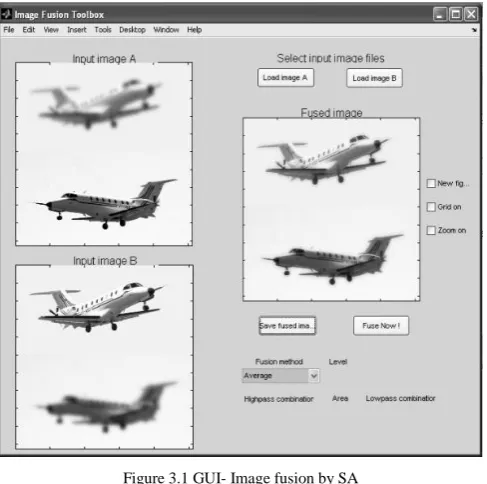
A. Simple Average:
It is a well documented fact that regions of images that are in focus tend to be of higher pixel intensity. Thus this algorithm is a simple way of obtaining an output image with all regions in focus.
n
i
y x Ii n SA
1 ) , (
1 (1)
[image:2.595.317.561.342.584.2]The value of the pixel P (i, j) of each image is taken and added. This sum is then divided by N to obtain the average. The average value is assigned to the corresponding pixel of the output image. This is repeated for all pixel values.
Figure 3.1 GUI- Image fusion by SA
B. Pyramid Fusion Algorithm:
With the introduction of pyramid transform in mid-80, some sophisticated approaches began to emerge [11]. People found that it would be better to perform the fusion in the transform domain. Pyramid transform appears to be very useful for this purpose.
The basic idea is to construct the pyramid transform of the fused image from the pyramid transforms of the source images, and then the fused image is obtained by taking inverse pyramid transform.
Typically, every pyramid transform consists of three major phases:
a. Decomposition
b. Formation of the initial image for decomposition.
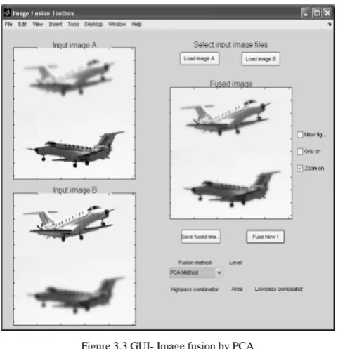
C. PCA Algorithm:
Let the source images (images to be fused) be arranged in two-column vectors. The steps followed to paper this data into 2-D subspaces are:
a. Organize the data into column vectors. The resulting matrix Z is of dimension 2 x n.
b. Compute the empirical mean along each column. The empirical mean vector has a dimension of 1 x 2. c. Subtract the empirical mean vector me from each
column of the data matrix Z. The resulting matrix X is of dimension 2 x n.
d. Find the covariance matrix C of X i.e. =XXT mean of expectation =
cov(
X
)
e. Compute the eigenvectors V and eigenvalue D of C and sort them by decreasing eigenvalue. Both V and D are of dimension 2 x 2.
f. Consider the first column of V which corresponds to
larger eigenvalue to compute
P
1andP
2 as1 2
(1) (2)
V V
P and P
V V
(2)
[image:3.595.318.559.51.300.2]Image Fusion by PCA
Figure 3.2 Information flow diagram in image fusion scheme employing PCA.
The input images (images to be fused)
1
,
2,
I x y
and I
x y
are arranged in two column vectors and their empirical means are subtracted. The resulting vector has a dimension of n x 2, where n is length of the each image vector. Compute the eigenvector and eigenvalues for this resulting vector are computed and the eigenvectors corresponding to the larger eigenvalueobtained. The normalized components
P
1 andP
21 2
. .,
1
i e P
P
using equation (3) are computed from theobtained eigenvector. The fused image is:
1 1 2 2
,
,
,
j
I
x y
P I x y
P I
x y
... (3)Figure 3.3 GUI- Image fusion by PCA
D. Discrete Wavelet Transform:
[image:3.595.37.290.159.538.2]The 2-Dimensional Discrete wavelet transform (2D-DWT), sometimes called wavelet decomposition, is the process to transform images from a spatial domain into a wavelet domain. The wavelet domain is the domain that represents the wavelet coefficients of the images. The wavelet decomposition can be done by passing an image into series of low-pass and high-pass filters.
Figure 3.4 Spatial Domain
Figure 3.5Wavelet Domain
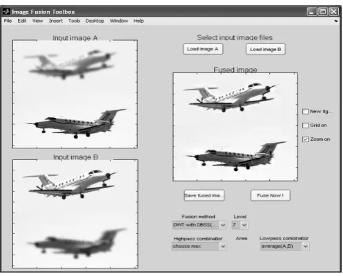
E. Image Fusion by DWT:
[image:3.595.334.514.411.646.2]Figure 3.6 Process of the DWT Image Fusion algorithm
The steps of the method in this paper are shown as follows:
Step 1: Read the two source images A and B to be fused.
Step 2: Perform wavelet decomposition on the input images.
Step 3: The low-frequency f
LL and high-frequency
,
f f
LH HL and f
HH coefficients are extracted. The
low-frequency coefficients are fused based on average method.
A B
LL and LL are the low frequency coefficients of input images A and B.
1
, , ,
f A B
LL avg LL i j LL i j (4)
Step 4: The high-frequency coefficients are fused based on taking the largest absolute value of pixels.
1
max , , ,
f A B
LH abs LH i j LH i j (5)
1
max , , ,
f A B
HL abs HL i j HL i j (6)
1
max , , ,
f A B
HH abs HH i j HH i j (7)
Step 5: Again, The low-frequency (
LL
f ) andhigh-frequency (
LH
f ,HL
fandHH
f) coefficients areextracted for same set of input images.
Step 6: The low-frequency coefficients are fused based on even degree. The even degree of a image block is defined as follows: Suppose the block has size of
N N
*
referred toas
B
k,
then, its even degreeJ
is:( , )
( , 1
( ) ( )
* K
k
K k
x y B k
f x y m
J B m
N N m
(8)
Where,
m
kis the average value ofB
K,( , )
f x y
denotes the pixel grey value in point( , )
x y
and(
m
k)
denotes a weight factor and can obtained by the formulaStep 7: Two input images
A
1 andA
2to be fused calculate their even degrees with the above formula. Then, the corresponding even degrees are calculated by comparingthe blocks to obtain the block
B
iof the fused image. Thefusion based principle is given by below:
1 1k 2 2k
,
(
1k)
2ki h
B
l A
l A
J A
JA
T
2 1k 1 2k, ( 1k) 2k
i h
B l A l A J A JA T (10)
1 2
2 ,
k k
i
B
A
A
otherwise
Step 8: The high-frequency coefficients are taking the largest absolute value of pixels.
1
max , , ,
f A B
LH abs LH i j LH i j
1
max , , ,
f A B
HL abs HL i j HL i j (11)
1
max , , ,
f A B
HH abs HH i j HH i j
Step 9: The inverse wavelet transform is applied to obtain the fused image.
Figure 3.7 GUI- Image fusion by DWT
IV. CONCLUSION
The DWT architecture presented here gives promising results in all test cases and can be further extended to all types of images by using different averaging, high -pass and low-pass filter masks. The variations in performance of fusion rules for different test images show that the choice of an optimum fusion rule depends mainly on the type of images to be fused, degradation models used to introduce noise in source images and the application. Hence using DWT architecture we can reconstruct sample images with plenty of information as compared to the traditional algorithms.
V. REFERENCES
[image:4.595.316.565.302.502.2]and Models in Computer Science, 2009. (Article in a conference proceedings)
[3] Florence Laporterie, Guy Flouzat, “Morphological Pyramid Concept as a Tool for Multi Resolution Data Fusion in Remote Sensing”, Integrated Computer-Aid Engineering, pp. 63-79, 2003.
[4] H. Li, B.S. Manjunath, and S.K. Mitra, Multi-sensor image fusion using the wavelet transform, Proceedings of the conference on Graphical Models and Image Processing, pp. 235_245, 1995.
[5] S. G. Mallat. “A Theory for Multiresolution Approximation and Wavelet Representation”. IEEE Trans. Pattern Anal. Machine Intell. ,1989, 11(7): 674-693
[6] M. Santos, G. Pajares, M. PortIela, et al. “ A New Wavelets Image Fusion Strategy. Pattern Recognition and Image Analysis”, pp. 919-926, 2003
[7] G. Pajares, J. M. D. L. Cruz, “A wavelet-based image fusion tutorial, “Pattern Recognition, vol. 37, no. 9, pp. 1855–1872, 2004.
[8] P. Vincent et al., "An approach to detailed dip determination using correlation by pattern recognition," Journal of Petroleum Technology, Feb. 1979, pp. 232-240.
[9] J. C. Trouiller et al., "Thin-bed reservoir analysis from borehole electrical images," SPE paper 19578, presented at the 64th Annual Technical Conference and Exhibition of the Society of Petroleum Engineers, San Antonio, Tex., Oct. 8-11, 1989.
[10] M. Kass et al., "Analyzing oriented patterns" Computer Vision, Graphics and Image Processing, 37, 362-385 (1987).
[11] P. Vincent et al., "An approach to detailed dip determination using correlation by pattern recognition," Journal of Petroleum Technology, Feb. 1979, pp. 232-240.