© 2014, IJCSMC All Rights Reserved 733 Available Online atwww.ijcsmc.com
International Journal of Computer Science and Mobile Computing
A Monthly Journal of Computer Science and Information Technology
ISSN 2320–088X
IJCSMC, Vol. 3, Issue. 3, March 2014, pg.733 – 739
RESEARCH ARTICLE
HIGH SPEED AND LOWER HARDWARE COMPLEXITY
VLSI ARCHITECTURE FOR LIFTING BASED
DISCRETE WAVELET TRANSFORM
K.Kokulavani
1, M.Mohankumar
2¹PG Scholar, Department of Electronics & communication Engineering, Sri Eshwar college of Engineering, India ²Assistant Professor, Department of Electronics & communication Engineering, Sri Eshwar college of Engineering, India
1
[email protected]; 2 [email protected]
ABSTRACT—A high speed and lower hardware complexity 2-D discrete wavelet transform architecture has been proposed. Previous DWT architectures are based on the modified lifting scheme or the flipping structure. Folded architecture method has been adopted. In the proposed architecture, modifications are made to the lifting scheme, and the intermediate results are combined to form the lifting elements. So as the number of registers can be reduced without extending the critical path., the two-input/two-output parallel scanning architecture is adopted in our design. For a 2-D DWT with the size of N × N, the proposed architecture requires three registers as data memory, and a higher efficiency can be achieved.
Keywords—Discrete Wavelet Transform (DWT), flipping structure, lifting scheme, pipeline, VLSI architecture .
I. INTRODUCTION
The Discrete Fourier Transform (DFT) may be thought of in general terms as a matrix multiplication in which the original vector
x
kis decomposed into a series of coefficientsX
n. Both k and n are integers which range over the same value N.
1
0
1 0
.
.
.
.
.
.
.
.
.
.
.
.
.
.
.
.
.
.
.
N kn
N
X
X
W
x
x
In the above we may derive the transformed coefficients
X
nby inverting the matrix. The form ofW
kn has many possibilities but physically we would like the option of forward and backward transforms i.e., an inverse ought to exist.The Discrete Wavelet Transform (DWT) generates a matrix
W
kn which is now widely used for image compression instead of the FT since it is able to localise preserve photographic detail such that many of the coefficients may be ignored (tantamount to filtering) and yet the reconstruction remains effective. For certain types of problems the filtering may be much more aggressive than corresponding FT coefficient filtering. (see “Numerical Recipes in C”, Prentice Hall, 2nd Ed. 1992, chapter 13).© 2014, IJCSMC All Rights Reserved 734
II. WAVELETS
A.The Haar Transform to get that Wavelet feel
Suppose for simplicity we assume an input vector
x
k with0
k
7
. This is readily decomposed into an obvious basis set as shown. 1 0 0 0 0 0 0 0 0 0 0 0 0 1 0 0 0 0 0 0 0 0 1 0 0 0 0 0 0 0 0 1 7 2 1
0 x x x
x
xk
Other basis systems are of course possible (remember your QM and spinors?). In 1910 Haar proposed the following decomposition. 1 1 0 0 0 0 0 0 0 0 1 1 0 0 0 0 0 0 0 0 1 1 0 0 0 0 0 0 0 0 1 1 1 1 1 1 0 0 0 0 0 0 0 0 1 1 1 1 1 1 1 1 1 1 1 1 1 1 1 1 1 1 1 1 7 6 5 4 3 2 1
0 a a a a a a a
a xk
or
x
n
H
nka
k with the columns of H being simply the above basis vectors and thea
kobtained by matrix inversion of H. These basis vectors have characteristic “shapes” when drawn on their side as shown in the figure on the next page and it is these shapes which show the essential features of what DWT decomposition does.
Notice:
o A mother or scaling function at the start with a non-zero average. This will normally be normalised to 1.
o Wavelet functions with zero average which are both compressed and translated. It is this compression and translation which finds peaks or pulses well.
o The wavelet functions are orthogonal. You can see this directly by multiplying any two together.
The wavelet functions have compact support which means they are all localised. This is unlike the FT in which the basis functions
exp(
2
nk
/
N
)
are continuous.© 2014, IJCSMC All Rights Reserved 735
B. Filtering the Coefficients
Filtering of wavelet coefficients is done by removing the smaller coefficients in the difference terms. In these terms are the detail which can often be removed without making a large difference to the overall structure. Two types of filtering exist.
1).Hard Thresholding: A difference term is treated as follows:
d
0
ifd
and otherwise is not touched.2)Soft Thresholding: As above but all other values for which
d
have the following operation done to them:d
sgn(
d
)(
d
)
This repositions the remainder of the coefficients. The literature suggests that
is best set ton
n
ln
2
. The standard deviation
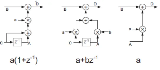
is taken over all the difference terms. „n‟ is the number of difference terms. III. LIFTING BASED DWT ARCHITECTUREDifferent kinds of lifting-based DWT architectures can be constructed by combining the three basic lifting elements. Most of the applicable DWTs like (9, 7) and (5 ,3) wavelets consist of processing units. This unit is called the processing element (PE). The processing nodes A, B and C are input samples which arrive successively. To implement the predict unit, A and C receive even samples while B receives odd samples. On the other hand, for the update unit, A and C are odd samples and B receives even samples. Now, the structure can be used to implement (5, 3) and (9, 7) wavelets. In this architecture each white circle represents a PE.
Fig 2 Basic functional units of lifting schemes
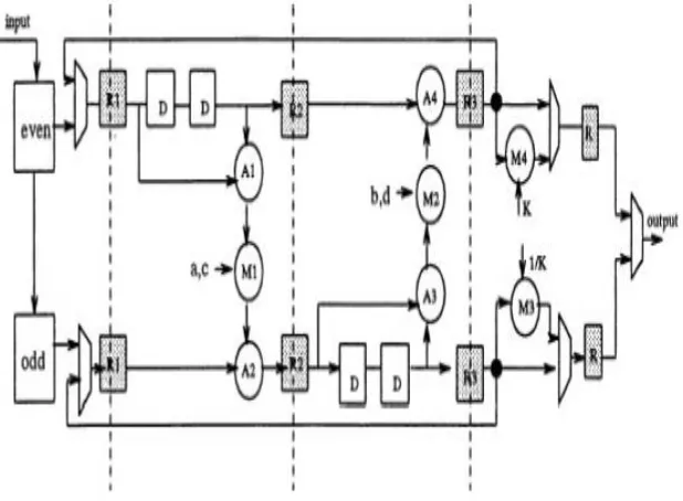
The input and output layers are essential (basic) layers and are fixed for each wavelet type, while by changing the number of extended layers, the type of wavelet can be changed accordingly. For example, omission of a single extended (added) layer structure will change the related architecture from (9, 7) type to (5,3) type. The black circles represent needed stored data for computing outputs (s, d). R0, R1 and R2, are registers that get their values from new input samples and are called data memory. The other three black circles which store the results of previous computations are known as temporary memory.
Fig. 3. Lifting structure for (5, 3) wavelet
© 2014, IJCSMC All Rights Reserved 736
of the data and temporary memories in the column-wise DWT unit determines the amount of needed internal memory. The pipeline registers do not affect the required internal memory. The data dependencies in the lifting scheme can be explained with the help of an example of DWT filtering with four factors as in equations [10, 11].The intermediate results generated in the first two stages for the first two lifting steps are subsequently processed to produce the high-pass (HP) outputs in the third stage, followed by the low-pass (LP) outputs in the fourth stage. For (9,7) filter is an example of a filter that requires four lifting steps. For the DWT filters requiring only two factors, such as the (5, 3) filter, the intermediate two stages can simply be bypassed.
IV. MINIMIZING HARDWARE ARCHITECTURES-PARALLEL AND DIRECT MAPPED ARCHITECTURES A direct mapping of the data dependency diagram into a pipelined architecture was proposed by Liu et al. in [23, 9] .For lifting schemes that require only 2 lifting steps, such as the (5,3) filter consists of two pipeline stages whereas for (9,7) it requires four pipeline stages reducing the hardware utilization to be only 50% or less. The architecture can be sequentially pipelined by combining the previous output of predict stage to current output.
The conventional lifting architectures for (5, 3) and (9, 7) consists of basic processing elements as shown in below Figure The cascaded blocks differ only in multiplier‟s coefficients. The delay unit represented by z−1 is implemented by one register. Each delay unit contains two consecutive registers. As shown the architecture contains one P and one U unit for (5, 3) wavelet.
Fig.4. Lifting based hardware architecture for (5, 3) wavelet
From the (5,3) wavelet implementation of the proposed architecture it is clear that only the number of coefficients and delay block registers, that is, the z−blocks, have been modified from four to two. So, changing the wavelet type changes these two quantities, coefficients and registers, only. The architecture for lossy (9, 7) wavelet is shown in Figure 5.
Fig.5. Direct architecture for (9, 7) wavelet
© 2014, IJCSMC All Rights Reserved 737 Fig. 6. Folded architecture for (5, 3) wavelet
For example the folded structure for (5, 3) and (9, 7) wavelets have two and four delay registers, respectively. Also the coefficients for (5, 3) wavelet are and while for (9, 7) they are a,b,c,d. The architecture can be reconfigured so that computation of the two phases can be interleaved by selection of appropriate data by the multiplexers.
As a result, two delay registers (D) are needed in each lifting step in order to properly schedule the data in each phase. Based on the phase of interleaved computation, the coefficient for multiplier M1 is either a or c, and similarly the coefficient for multiplier M2 is b or d. The hardware utilization of this architecture is always 100% and the critical path in the multiplier can be reduced.
Fig.7. Folded architecture for (9,7) wavelet
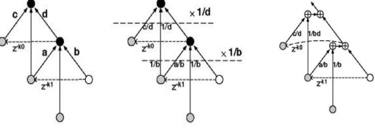
V. Flipping Architecture
© 2014, IJCSMC All Rights Reserved 738
Fig. 8. Flipping architecture (a) Two connected computing units (b) Flipping computing units(c) After splitting the computing units and merging the multipliers.
TABLE I
COMPARISION BETWEEN EXISTING ARCHITURE AND PROPOSED
VI. Simulation Result A. 2-D Discrete Wavelet Transform
ARCHITCTURE
MINIMUMUM TIME REQUIRED
MINIMUM INPUT TIME
BEFORE CLOCK
MAXIMUM O/P TIME REQUIRED AFTER CLK
CRITICAL PATH DELAY
TOTAL EQUIVALENT GATE COUNT FOR DESIGN
ADDITIONAL JTAG GATE COUNT FOR
IOBS
Existing
architecture
8.712ns
2.245ns
6.347ns
8.49 ns
9,596
2,352
Proposed
© 2014, IJCSMC All Rights Reserved 739
VII. CONCLUSION
In this , we have proposed a architecture for the 1- and 2-D DWTs.Compared to the previous architectures the folded architecture method has reduced the hardware complexity , no of registers and critical path delay.The proposed method has also reduced the memory space. This review is useful for exploring a new method of pipelined architectures capable of handling multiple data streams suitable for application in image and video processing multimedia real time applications.
REFERENCES
[1] G. Xing, J. Li, and Y. Q. Zhang, “Arbitrarily shaped video-object coding by wavelet,” IEEE Trans. Circuits Syst. Video Technol., vol. 11, no. 10, pp. 1135–1139, Oct. 2001.
[2] S. C. B. Lo, H. Li, and M. T. Freedman, “Optimization of wavelet decomposition for image compression and feature preservation,” IEEE Trans.Med. Imag., vol. 22, no. 9, pp. 1141–1151, Sep. 2003.
[3] K. K. Parhi and T. Nishitani, “VLSI architecture for discrete wavelet transforms,” IEEE Trans. Very Large Scale Integr. (VLSI) Syst., vol. 1, no. 2, pp. 191–202, Jun. 1993.
[4] P.Wu and L. Chen, “An efficient architecture for two-dimensional discrete wavelet transform,” IEEE Trans. Circuits Syst. Video Technol., vol. 11, no. 4, pp. 536–545, Apr. 2001.
[5] W. Sweldens, “The new philosophy in biorthogonal wavelet constructions,” in Proc. SPIE., 1995, vol. 2569, pp. 68–79. [6] I. Daubechies and W. Sweldens, “Factoring wavelet transform into lifting steps,” J. Fourier Anal. Appl., vol. 4, no. 3, pp. 245– 267, Mar. 1998.
[7] J. M. Jou, Y. H. Shiau, and C. C. Liu, “Efficient VLSI architectures for the biorthogonal wavelet transform by filter bank and lifting scheme,” in Proc. IEEE ISCAS, May 2001, vol. 2, pp. 529–532.
[8] G. Shi, W. Liu, and L. Zhang, “An efficient folded architecture for lifting based discrete wavelet transform,” IEEE Trans. Circuits Syst. II, Exp. Briefs, vol. 56, no. 4, pp. 290–294, Apr. 2009.
[9] B. F. Wu and C. F. Lin, “A high-performance and memory-efficient pipeline architecture for the 5/3 and 9/7 discrete wavelet transform of JPEG2000 codec,” IEEE Trans. Circuits Syst. Video Technol., vol. 15, no. 12, pp. 1615–1628, Dec. 2005.
[10] Y. K. Lai, L. F. Chen, and Y. C. Shih, “A high-performance and memory-efficient VLSI architecture with parallel scanning method for 2-D lifting-based discrete wavelet transform,” IEEE Trans. Consum. Electron., vol. 55, no. 2, pp. 400–407, May 2009. [11] C.-T. Huang, P.-C. Tseng, and L.-G. Chen, “Flipping structure: An efficient VLSI architecture for lifting-based discrete wavelet transform,” IEEE Trans. Signal Process., vol. 52, no. 4, pp. 1080–1089, Apr. 2004.
[12] P.-C. Tseng, C.-T. Huang, and L.-G. Chen, “Generic RAM-based architecture for two dimensional discrete wavelet transform with line based method,” in Proc. Asia-Pacific Conf. Circuits Syst., 2002, vol. 2, pp. 363–366.
[13] C. Xiong, J. Tian, and J. Liu, “Efficient architectures for two-dimensional discrete wavelet transform using lifting scheme,” IEEE Trans. Image Process., vol. 16, no. 3, pp. 607–614, Mar. 2007.
[14] H. Liao, M. K. Mandal, and B. F. Cockburn, “Efficient architectures for 1-D and 2-D lifting-based wavelet transforms,” IEEE Trans. Signal Process., vol. 52, no. 5, pp. 1315–1326, May 2004.
[15] C.-Y. Xiong, J.-W. Tian, and J. Liu, “A note on „flipping structure: An efficient VLSI architecture for lifting-based discrete wavelet transform‟,” IEEE Trans. Signal Process., vol. 54, no. 5, pp. 1910–1916, May 2006.
[16] C. Cheng and K. K. Parhi, “High-speed VLSI implement of 2-D discrete wavelet transform,” IEEE Trans. Signal Process., vol. 56, no. 1, pp. 393–403, Jan. 2008.
[17] B. K. Mohanty and P. K. Meher, “Throughput-scalable hybrid-pipeline architecture for multilevel lifting 2-D DWT of JPEG 2000 coder,” in Proc. IEEE Int. Conf. Appl.-Specific Syst., Archit. Processors, 2008, pp. 305–309.
[18] J. Song and I.-C. Park, “Novel pipelined DWT architecture for dual-line scan,” in Proc. IEEE Int. Symp. Circuits Syst., 2009, pp. 373–376.
[19] Z. G.Wu andW.Wang, “Pipelined architecture for FPGA implementation of lifting-based DWT,” in Proc. Int. Conf. Elect. Inform. Control Eng., 2011, pp. 1535–1538.