INTERNATIONAL JOURNAL OF SCIENTIFIC & TECHNOLOGY RESEARCH VOLUME 8, ISSUE 09, SEPTEMBER 2019 ISSN 2277-8616
Geographic Multiattribute Monarch Butterfly
Optimization Based Traffic Aware Routing in
VANET
R Brendha, V Sinthu Janita PrakashAbstract— VANET is a decentralized network where the vehicles moved in any direction. Due to the random movement of the vehicle, wireless communication takes place and the data are sent from source to destination with the geographical positions of neighboring nodes. Several methods have been developed for routing the data packets. But the traffic aware routing is still a challenging issue in VANET. A technique called Geographic Multiattribute Monarch Butterfly Optimized Traffic-Aware Routing (GMMBOTAR) is introduced to improve the packet delivery ratio and minimize the delay as well as routing load. Populations of ‘n’ monarch butterflies (i.e. vehicle nodes) are initialized randomly in search space (i.e. network). After the initialization, the source node finds the nearest intersection point’s closest to the destination node. Then the source node starts to find the optimal neighboring node to forward the data packets. In this technique, optimal neighboring node searching process is performed using Multiattribute Monarch Butterfly Optimization. The multiattributes used for the selection of neighboring node is received signal strength, distance, the battery power of the node, reliability pair factor and node cooperativeness. Initially, the fitness of each vehicle node is computed based on the multiple attributes with their threshold ranges to find the optimal neighboring node. Due to the mobility, the position of the nodes gets updated and finds the optimal neighbor node is found based on butterfly migration operator and butterfly adjusting operator. Finally, the route path from the source node to the destination is established using route request (REQ) and route reply (REP) distribution. The simulation results confirm that the Geographic Multiattribute Monarch Butterfly Optimized Traffic-Aware Routing (GMMBOTAR) technique effectively improves the packet delivery ratio, throughput and minimizes the collision rate, average end to end delay as well as normalized routing load than the state-of-the-art methods.
Index Terms—VANET, Traffic-aware Geographic routing, Multi-attributes Monarch Butterfly Optimization. ————————————————————
1 I
NTRODUCTION AVANET is a rising technology to offer wireless communication between moving vehicles. Routing in VANET is difficult due to the dynamic movement of the vehicle nodes. Therefore, road intersections based approach is developed through which a data packet transmitted to reach the destination through the intermediate vehicle nodes. A lot of research works have been designed to solve the traffic aware routing in a dynamic environment. An improved genetic algorithm-based route optimization technique (IGAROT) was introduced in [1] that ensure reliable communication. But the technique failed to perform the traffic aware routing for achieving the higher packet delivery. A maximum distance on-demand routing algorithm (MDORA) was designed in [2] to select the optimal route based on the distance to ensure the completion of the data transmission process. The algorithm does not minimize the packet drop due to the traffic in the dense environment. A connectivity-aware intersection based routing (CAIR) protocol was introduced in [3] to route the data packets by using the road traffic characteristics. The designed protocol minimizes the delay but the packet delivery ratio was not improved. An Ant Colony Optimization (ACO) based algorithm was designed in [4] for effectively selecting the best routing path. But the algorithm failed to consider the road segment based route path selection for minimizing the delay. A Particle swarm optimization technique was introduced in [5] to route the data packetsbetween the vehicles with higher packet delivery and minimum delay. The designed technique failed to deal with high topology changes under various network conditions. A hybrid ant colony optimization (HACO) was introduced in [6] for selecting an optimal route path to route the data packets. The HACO did not achieve higher data delivery and minimum routing load. A bio-inspired cognitive agent optimization technique was introduced in [7] for vehicles routing with available road segments. The optimization technique failed to consider both the optimal neighboring node selection and road segment for minimizing the delay. A modified lion algorithm was developed in [8] for finding the route path with minimum cost. But the performance of the data delivery remained unsolved.
A Geographical Zone clustered Multi-objective Glowworm swarm optimized Routing (GZMGR) technique was developed in [9] for routing the data packets with minimum delay. The designed routing technique failed to consider the other mobility parameters such as signal strength, node cooperativeness and so on for further improving the throughput and packet delivery ratio. A VANET routing protocol based on ant colony optimization (VACO) was developed in [10] for traffic-aware routing with minimum delay and overhead. But the designed VACO algorithm failed to achieve the higher throughput. To overcome the above-said issues and to effectively perform traffic-aware routing a new technique called GMMBOTAR is proposed. The contributions of the GMMBOTAR technique are described as follows, GMMBOTAR technique is introduced to achieve high
packet delivery with minimum end to end delay. Initially, the source node uses the argument of a minimum function to find the neighboring intersection. Followed by, the
————————————————
R.Brendha is currently pursuing Phd degree program in computer science in Bharthidasan University, India, E-mail: [email protected]
INTERNATIONAL JOURNAL OF SCIENTIFIC & TECHNOLOGY RESEARCH VOLUME 8, ISSUE 09, SEPTEMBER 2019 ISSN 2277-8616
2052 neighboring vehicle nodes are identified by applying
Monarch Butterfly optimization based on the multiple attributes. This optimization technique finds the best vehicle node by calculating the fitness. Then the route between the nodes is established and the data packets are transmitted. This helps to achieve higher delivery ratio and minimum delay.
The GMMBOTAR technique considerably reduces the normalized routing load in the route discovery phase by minimizing the number of control packets generation. In the route discovery phase, GMMBOTAR technique uses the less number of control packets i.e. REQ and REP instead of using other packets such as RRER (route error) and so on for finding the optimal route path. This helps to minimize the number of control packet generations and reduced the collision rate.
The optimization technique effectively selects the optimal route path between the source and destination to successfully deliver the data packets without any loss. This helps to improve throughput.
The remainder of the paper is organized as follows. Section 2 describes the related works. Section 3 describes the proposed GMMBOTAR technique with a neat diagram. In Section 4, the simulation setting is presented and the performance results are discussed in Section 5. Section 6 provides the conclusion of the work.
2
R
ELATEDW
ORKSA fractional glowworm swarm optimization (FGWSO) technique was developed in [11] to select the best path for vehicle communication with minimum traffic density and delay time. The designed optimization algorithm failed to consider the several constraints for finding the route path. An artificial bee colony (ABC) algorithm was proposed in [12] for selecting the neighbors with multiple criteria. Though the algorithm increases the packet delivery, the routing load was not minimized. A real-time intersection-based segment aware routing (RTISAR) algorithm was presented in [13] to discover the optimal route for data packets transmission by utilizing traffic segment condition. The designed algorithm minimizes the overhead but the packet drop was not minimized. An efficient and stable routing algorithm was developed in [14] based on mobility and density to find the reliable route between the nodes for end-to-end data delivery. The algorithm failed to consider traffic based routing to minimize the collision. A Reliable Traffic Aware Routing (RTAR) protocol was designed in [15] for the vehicle to vehicle communication in VANET. The next forwarder and current forwarder node selection remained unaddressed to achieve reduced routing load. The designed protocol did not provide stable and efficient communication in an urban environment. In [16], a Real-Time Intersection-based Segment Aware Routing (RTIASR) protocol was developed for data delivery with minimum delay and less communication overhead. This algorithm failed to consider the received signal strength. A traffic-aware routing protocol was designed in [17] for improving the routing performance with higher data delivery over a vehicular environment with minimum delay. The routing load was not minimized. Ant-based vehicle congestion avoidance system was developed in [18] with less
traffic density. Though the system minimizes the communication overhead, the delivery ratio was not minimized. The above-said issues are overcome by proposed a novel technique called GMMBOTAR is explained in the next section.
3
M
ETHODOLOGYA VANET is an ad-hoc network where contributing vehicles and other neighboring vehicles are allowed to communicate the data by the wireless transceiver. VANET is an infrastructure less networks and offers wireless communication between the moving vehicles. In VANET, the various issues like traffic accidents and congestion during the peak hour in an urban area raise the difficulty in handling the traffic. To resolve these problems, traffic-aware optimal paths are discovered to route the data packets. Every vehicle node is responsible for dynamically identifying its neighbors to communicate directly with them. The efficient neighboring nodes are used to transmit and forward the data between the source and the destination. Therefore, the major problem of VANET is to identify the optimal neighboring node for sending the data. Based on this motivation, Geographic Multiattribute Monarch Butterfly Optimized Traffic-Aware Routing (GMMBOTAR) technique is introduced.
3.1 System model
In this section, the system model of the proposed GMMBOTAR technique is presented. Let us consider the squared sensing area n*n, where the nodes are randomly deployed. A VANET represented by a graph G = (v, e) where ‗v‘ indicates a number of vehicle nodes vn , vn , vn , … . , vnn and ‗e‘ represents the edges i.e. links between the vehicle nodes. The source vehicle node (SN) sends the data packets
DP = DP , DP , DP , … , DPn to the destination node
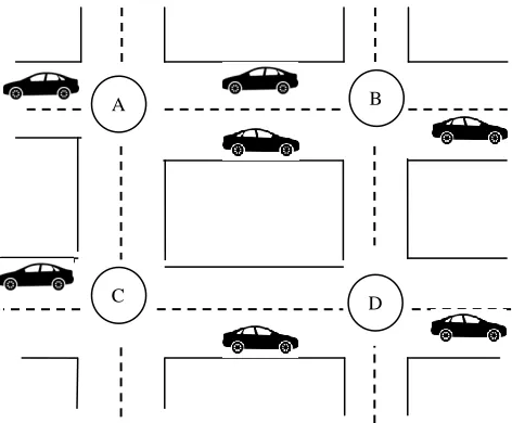
(DN)through optimal neighboring nodesnn = nn , nn , … , nnn. The proposed GMMBOTAR technique performs intersection based traffic aware routing as shown in Fig. 1.
Fig. 1. Intersection based Routing in VANET
Fig. 1. illustrates the intersection based routing in VANET where the vehicle nodes are distributed in a road map. In the above figure, four intersections such as A,B,C,D ∈ G if and
B A
INTERNATIONAL JOURNAL OF SCIENTIFIC & TECHNOLOGY RESEARCH VOLUME 8, ISSUE 09, SEPTEMBER 2019 ISSN 2277-8616 only if there is a road segment connecting intersections and
vehicles can travel on that segment. At each intersection, there is a traffic system that controls the movement of vehicles using traffic light pattern with a color code such as red, green and yellow. Based on this system model, the proposed Geographic Multiattributes Monarch Butterfly Optimized Traffic Aware Routing (GMMBOTAR) technique is designed. VANET, initialize the populations of Monarch Butterflies i.e. numbers of vehicle nodes 𝑣𝑛 , 𝑣𝑛 , 𝑣𝑛 , … . , 𝑣𝑛 in a random manner. Then the source node finds the nearest intersection (i.e. junction) to the destination is selected for routing the data packets. After finding the intersection, the source node initiates the data packets and finds the adjacent vehicle node to forward the data packets. The nearest optimal vehicle nodes are determined through the multiple attributes of the vehicle nodes. After selecting the neighboring node, the route path from the source to the destination is identified and the data packets are routed.
Neighboring road intersection selection
The total network consists of a number of road segments (i.e. intersections) in which the vehicles are moving. The intersection based routing has less overhead compared to other routing techniques since the packets only transmit to the next intersection and the position of the destination. This helps to avoid network traffic. Initially, the source vehicle node (SN) in the one intersection point finds the nearest road intersection closest to destination vehicle node (DN) based on the distance calculation. Let us consider the two-dimensional space, the coordinate of the source node is (x_1,y_1) and the coordinate of the source intersection point is (x_2,y_2). Then the distance between these two points are computed as follows,
d = √(x − x ) + (y − y ) (1)
In (1), d represents the distance between the source node SN and road intersection point ‗IP ‗closet to the destination vehicle node. Then the source node finds the nearest intersection point to the destination.
arg min d (2)
In (2), argmin represents the argument of minimum,d represents the distance. Therefore the source node uses the argument of a minimum function to find the intersection point with minimum distance. After finding the nearest junction (i.e. intersection point), the optimal one hop neighboring nodes are determined using multi-attribute optimization technique.
Multi-attribute monarch butterfly optimization for optimal neighboring node selection
After finding the nearest intersection, the source node selects the optimal neighboring node to route the data packets from the source to the destination. The neighboring node selection is performed using the multiattribute monarch butterfly optimization technique. The multiattribute monarch butterfly optimization is a metaheuristic technique that provides a better solution for the optimization problem. In the proposed GMMBOTAR technique, multiattribute represents that more objective functions are used for solving the optimization problem. The proposed GMMBOTAR technique performs efficient traffic-aware routing with multi-attribute such as
received signal strength, distance, the battery power of the node, reliability pair factor and node cooperativeness. The proposed GMMBOTAR technique initializes the population of the monarch butterfly individuals (i.e. vehicle nodes) vn , vn , vn, … . , vnn randomly in the search space. After the initialization, the fitness of each individual is computed based on the multiple attributes. Multiple attributes are multiple objective functions which are mathematically formulated as follows,
f(x) = *f (x), f (x), f (x), f (x), f (x)+ (3)
In (3),f(x) denotes an objective function, f (x) denotes received signal strength, f (x) represents the distances, f (x) denotes a battery power of the node, f (x) is a reliability pair factor between the nodes, f (x) denotes node cooperativeness. The different objective functions are defined as follows
Received Signal Strength
The first attributef (x) is the received signal strength (RSS) is a measurement of how the vehicle nodes received a power level from the other vehicle node. It is also used to find the relationship between the transmitted power, the receive power and distance. For each vehicle node, the antenna is deployed for proper radio communication. The received signal power is measured using two ray ground model as follows,
RSS = h h
TSS (4)
where (4), RSS is the received signal strength (i.e. received power level) of the vehicle node, T and R represents a transmitter and receiver antenna (deployed in each vehicle) gain, T represents a height of transmitter antenna, R denotes a height of receiver antenna, D indicates the distance between transmitter and receiver, TSS denotes a transmitted signal power. The received signal strength is indirectly proportion to the distance. It means that, while increasing the distance between the two nodes, the signal strength becomes poorer.
Distance
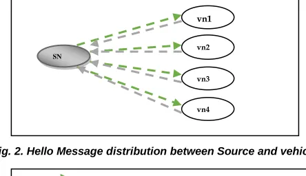
The second attribute f (x) is the distance between the source node and another number of vehicle nodes in the network. The distance is measured using Time of Flight (ToF) which is defined as the hello message transmitted from the source node and reply message return from the other vehicle nodes.
Fig. 2. Hello Message distribution between Source and vehicle nodes
Fig.2. illustrates a Hello message distribution between source and vehicle nodes. The source node (SN) distributes a Hello message to all the vehicle nodes for finding the distance
SN
vn1
vn2
vn3
vn4
INTERNATIONAL JOURNAL OF SCIENTIFIC & TECHNOLOGY RESEARCH VOLUME 8, ISSUE 09, SEPTEMBER 2019 ISSN 2277-8616
2054 between them. After receiving the hello message, other vehicle
nodes (vn) sends reply message to the source node. The Time of Flight (ToF) is calculated as follows,
D = R − T (5)
In (5),D denotes a distance between the source node and other neighboring nodes, R denotes a time for replying the message, T denotes a hello message transmission time. If the vehicle node sends the reply back to the source node with minimum time, then the node is located with minimum distance.
Battery power of the node
The another attribute f (x) is the battery power of the node. The battery power is the major factor affecting the network lifetime since the less powered node does not have the ability to either accept the data or send the data to other nodes in the network. Therefore, the capacity of the battery is expressed in milliampere-hours (mAh). The remaining battery power of the node is computed as follows,
P = P− P (6)
In (6),P denotes a remaining battery power of the vehicle node, P denotes a total battery power of the vehicle node, P denotes a consumed power of the node.
Reliability Pair factor
The fourth attribute f (x) is the reliability pair factor which is formed at a source node with one of its neighboring nodes. Reliability pair is the set of two vehicle nodes connected between them using the reliable links. Link connectivity between the vehicles nodes involved in communication is based on the distance between them, the power level of the nodes and received signal strength. Therefore, reliability pair factor is directly proportional to the sum of the maximum remaining power level of the nodes as well as signal strength and inversely proportional to the distance between them.
R = α m ( ( ), ( n)) (7)
In (7)R denotes a reliability pair factor, α denotes a proportionality constant, max(P (SN), P (vn)) denotes a maximum battery power of the source node P (SN) and the battery power of the vehicle node P (vn). RSSdenotes a received signal strength. D denotes a distance between the source node and other vehicle nodes.
Node Cooperativeness
The final attribute f (x) is the cooperativeness (CC) which determines the links between the nodes over the time. Therefore, the vehicle node in the network is responsible for managing the links to improve the end-to-end connectivity. A group of vehicle nodes is involved in transmitting data from source to destination through the concept of neighboring node cooperation. The node with better cooperativeness is selected as an optimal neighboring node for data transmission. Let us consider the two vehicle nodes vn and vn. the links between these two nodes are established through the beacon messages transmission namely B m and B m . The node vn sends B m to vn over the time is expressed as follows,
vn (B m ) → vn (8)
The vehicle node vn receives the B m message and it sends reply messages (B m )back tovn .
vn (B m ) → vn (9)
If the vn sends a reply message to the node vn , then the node vn is connected to the vn at the particular time instant . If the node vn does not receives the reply message, link vn and vn are not connected at a time‗t‘. Based on this link estimation, the cooperative count of the particular node is estimated. Therefore, the node with better cooperativeness is selected as an optimal neighboring node for data transmission.
Based on the above said multiple attributes such asf (x), f (x), f (x), f (x), f (x), the Fitness(F) of the node is computed as follows,
Fitness = *(RSS > RSS )&&(min D)&&(P > P )&&(R > R ) &&(betterCC)+ (10)
In (10),RSSdenotes a received signal strength, RSS denotes a threshold of the received signal strength,min D denotes a minimum distance between the source and other nodes, P the remaining battery power of the node, P denotes a threshold of the remaining battery power of the node.R represents a reliability pair factor, th is the reliability pair factor threshold, CC denotes a node cooperativeness.
The source node selects the optimal vehicles nodes based on criteria,
When the signal strength of vehicle nodes is greater than the threshold i.e. RSS > RSS
Minimum distance between the source and vehicle node i.e..min D.
When the remaining battery power of the node is greater than the threshold value i. eP > P
When the reliability pair factor between the source and other vehicle is greater than the threshold value i. e(R > th)
When the nodes provide the better cooperativeness i.e. betterCC
INTERNATIONAL JOURNAL OF SCIENTIFIC & TECHNOLOGY RESEARCH VOLUME 8, ISSUE 09, SEPTEMBER 2019 ISSN 2277-8616
Butterfly migration operator
The first searching process of the multiattribute monarch butterfly optimization metaheuristics is guided by a migration operator. Child monarch butterfly (i.e. subpopulation 1) individual is generated by migration operator from the population.
y ,m = {
y ,m ; v ≤ r y ,m ; v > r (11)
In (11),y ,m denotes anm element of the y in the generation‗t+1‘ that presents the position of the monarch butterfly ‗i‘ (i.e. vehicle node), y ,m indicates an m element of the y in the generation ‗t‘ that is the newly generated position of the monarch butterfly b , y ,m represents the m element of the y in the generation ‗t‘. b andb are the Monarch butterfly that is randomly selected from Subpopulation P and P respectively. By using the above equation (11), whenv ≤ r, the element ‗m‘ in the newly generated monarch butterfly ‗b ‘is generated. On the contrast, if v > r the element ‗m‘ in the newly generated monarch butterfly ‗b ‘ is generated. In (11), r is the ratio of monarch butterflies in a subpopulationP. ‗v‘ is the random number which is computed as follows,
v = rn tm (12)
In (12),rn is the random number between [0, 1], tm denotes a migration time period is set to 1.2. The above analysis shows that the monarch butterfly optimization balances the direction of migration operator by adjusting the ratio ‘r‘. If r is large, more elements from the monarch butterflies in a subpopulation P are selected. If ‗r‘ is small, more elements from monarch butterflies in a subpopulation P are selected.
Butterfly adjusting operator
The second method is the butterfly adjusting operator that guides the monarch butterflies searching process. The positions of the monarch butterflies (i.e. vehicle nodes) are updated through the butterfly adjusting operator. For each monarch butterfly in the subpopulation P, the position is updated as follows. If the randomly generated a number is lesser than the ratio ‗r‘, the position is updated as follows,
y ,m = {y ,mifv ≤ r
y ,mifv > r (13)
In (13), y ,m represents the m element of the y in the generation‗t+1 that provides the position of the monarch butterfly ‗j‘ in the subpopulation ‗P‘. y ,mdenotes a m element of the y that is the best monarch butterfly in subpopulation 1 and subpopulation2. ‗t‘ is the current generation. If the random number ‗v‘ is greater than the ratio ‗r‘, y ,m indicates am element of the y that is randomly chosen in the subpopulation 2. If the random number is greater than the butterfly adjusting rate (B ) . The update process is formulated as follows,
y ,m = y ,m + β .dym− / (14)
In (14),β denotes a weighting factor and dym denotes the
walk step of the monarch butterfly ‘j‘. The weighting factor is defined as follows,
β = (15)
In (15),stm represent the maximum walk step that a monarch butterfly individual moves in one step and‗t‘ is the current generation. Finally, the two subpopulations from the migration and adjusting operators are combined into one whole population. Then the fitness is calculated for newly-generated monarch butterflies. From that, the current best monarch butterfly (i.e. vehicle node) is selected and their position updated.
Route Path discovery
After selecting the optimal neighboring node, the source node identifies the route path between them for routing the data packets to the destination. The route between the source node and neighboring nodes are established through the two control messages distributions namely route request (REQ) and route reply (REP). Initially, the source vehicle node sends request messages (REQ) to the optimal neighboring node.
SN ( )→ nn ( )→ DN (16)
From (16), SN denotes a source node, nn denotes an optimal neighboring node,DNrepresents the destination vehicle node. The symbol ‗→ ′ denotes a forwards the request packet to the destination. After receiving the REQ message, the reply from the destination to source through the intermediate nodes which is expressed as follows,
DN ( )→ nn ( )→ SN (17)
Based on the REQ and REP message distribution, the optimal route path between the source and destination is identified and transmits the data packets along the route path. The source node sends the data packets to the destination through a number of intersections and segments in the road. If any data traffic congestion occurring at the intersection, the link quality is low, hence the source node performs routing with neighbor intersection through the buffer capacity and the channel utilization. The buffer capacity is computed as follows,
b (t) = ( ) ( ) ( ) (18)
INTERNATIONAL JOURNAL OF SCIENTIFIC & TECHNOLOGY RESEARCH VOLUME 8, ISSUE 09, SEPTEMBER 2019 ISSN 2277-8616
2056 Output: Improve traffic-aware routing
Begin
1. Initialize the population of vehicle nodes vn , vn , vn , … . , vnn
2. SN finds the intersection nearest to the destination through the distance
3. Source node initiates DP and find the nearest vn
4. For each vn
5. Calculate RSS, D, P , R , CC
6. Compute fitness F
7. end for
8. While (t < max_iteration)
9. Sorting
vn
in a descending order based on fitness10. If (F > F ) then
11. Generate new subpopulation 1 using Migration operator
12. Update the positions of the butterflies y ,m
13. Else
14. Generate new subpopulation 2 using butterfly adjusting operator
15. Update the positions of the butterflies y ,m
16. End if
17. Combine newly generated subpopulation 1 and subpopulation 2 into one whole population
18. Evaluate the fitness according to the newly updated positions
19. Increase iteration count t = t + 1
20. End while
21. Return best optimal vehicle node vno
22. if multiple hops between SN and DN then
23. vno performs step 4 to step 21
24. Find another optimal neighboring node
25. end if
26. Repeat step 4 to 24 until all optimal node is found between SN and DN
27. SN sends REQ to DN through
𝑛𝑛
𝑖28. DN reply through
𝑛𝑛
𝑖 to SN29. Construct route between SN and DN
30. SN forwards the DP along the route path to DN End
Algorithm 1. Geographic Multi-attributes Monarch Butterfly Optimized Traffic-Aware Routing
The algorithm describes the Geographic Multi-attributes Monarch Butterfly Optimized Traffic-Aware Routing in VANET. The source node finds the nearest intersection point to the destination through the distance measure. Then the source node sends data packets to the destination node through the neighboring node and the intersection. For each vehiclenode in the search space, the multiple attributes such as received signal strength, distance, remaining battery power, reliability pair factor and node cooperativeness are calculated. The fitness is computed based on the multiple attributes. Based on fitness, the vehicle nodes are sorted in descending order. After sorting, the nodes are divided into two subpopulations by setting the fitness threshold. Due to the movement of the vehicle node, the position of the node gets
updated based on the migration and adjustment parameter. Then the newly generated two subpopulations are combined into one and again compute the fitness according to the updated position of the vehicle nodes. This process is repeated until the maximum iteration is reached. Finally, the current best individual is selected as the optimal vehicle node for routing the data packets. Then the newly selected neighboring node performs the same operation for finding the other neighboring node. Similarly, optimal neighboring nodes from source to destination are selected. After finding the optimal neighboring node, the route path is established between source and destination. If any congestion occurred in the junction point, the source node finds the nearest intersection point to minimize the network traffic. This helps to improve the data packet delivery between the source and destination with minimum end to end delay.
4
S
IMULATIONS
ETTINGSThe simulation of the GMMBOTAR technique and existing methods namely GZMGR [9] and VACO [10] are implemented using NS2.34 simulator. The simulation parameters are listed in table 1.
TABLE1
SIMULATION PROPERTIES
Simulation parameter Value
Simulator NS2 .34
Network area 1500m * 1500m
Number of vehicle nodes 50 to 500
Protocol DSR
Simulation time 300sec
Mobility model Random Way Point
model
Nodes speed 0-20m/s
Data packet 100
Number of runs 10
The simulation is performed with the above-said simulation parameters with changing the number of nodes. The simulation results of different parameters are discussed in the next section.
5
R
ESULTS ANDD
ISCUSSIONThe simulation results of GMMBOTAR technique and existing methods namely GZMGR [9] and VACO algorithm [10] are mentioned in this section. The performance of proposed GMMBOTAR technique and existing methods are evaluated with different parameters such as packet delivery ratio, average end to end delay, collision rate, normalized routing load and throughput with respect to a number of nodes and data packets.
5.1 Simulation results of packet delivery ratio
The packet delivery ratio is mathematically calculated as follows.
Packetdeliveryratio = ,Number of datapacket received/ Number of datapacket sent- 100 (19)
INTERNATIONAL JOURNAL OF SCIENTIFIC & TECHNOLOGY RESEARCH VOLUME 8, ISSUE 09, SEPTEMBER 2019 ISSN 2277-8616 technique improves the packet delivery. The simulation
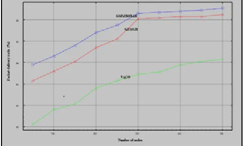
results of the packet delivery ratio using three different methods GMMBOTAR, VACO [9], GZMGR [10] are illustrated in Fig. 3.
Fig. 3. Performance Results of Packet Delivery Ratio
Fig. 3. depicts the performance results of the packet delivery ratio using three different techniques. The numbers of nodes are taken as input in the ‗x‘ axis and the results of the packet delivery ratio are obtained at the ‗y‘ axis. The above graphical result confirms that the GMMBOTAR technique increases the packet delivery ratio than the existing optimization techniques. This is because of GMMBOTAR technique finds the optimal neighboring node with five different attributes. The fitness of the nodes is calculated with these attributes and identifies the optimal node is identified. After finding the neighboring node, the routes are established for sending the data packets between the source and destination. The source node starts to send the data packets along the stable route path from the source to the destination. This helps to improve the data packet delivery. Ten different results of the packet delivery ratio of GMMBOTAR technique is compared to the existing optimization techniques.
5.2 Simulation results of Average end to end delay
The mathematical formula for calculating the average end to end delay is given below,
AEED =
um o ll p k d l yum o d
(20)
Sumofallpacketsdelay = ∑( T − T ) (21)
In (20) (21),AEED denotes an average end to end delay, DP represents the data packets, T denotes a packet arrival time, T denotes a packet sending time. The AEED is measured in the unit of seconds (S). The reported result confirms that the delay is considerably minimized using GMMBOTAR technique when compared to the conventional optimization techniques such as GZMGR [9] and VACO [10]. The simulation results of the end to end delay using proposed and existing methods with the number of vehicle nodes are shown in Fig. 4.
Fig. 4. Performance Results of Average end to end delay
Fig. 4. depicts the performance results of the average end to end delay with respect to a number of vehicle nodes. As shown in Figure 5, the conventional optimization technique takes more delay for receiving the data packets at the destination than the proposed GMMBOTAR technique. This is because the GMMBOTAR technique performs the intersection based routing for avoiding the traffic. Before routing the data packets, the source node selects the nearest intersection point towards the destination. After finding the intersection, the neighboring nodes selection between source and destination helps for transmitting the data packets. Then the data packets are transmitted to the destination through the selected intersection and optimal neighboring node resulting in increasing the packet delivery and minimizing the end to end delay.
5.3 Simulation results of Collision Rate
The collision rate is calculated using the following mathematical formula,
collisionrate =
um o p k d opp d (m ) (22)From (22), T represents the time in millisecond (ms). The Collision rate is measured in terms of packets per seconds (PPS). While transmitting the number of data packets, a few data packets are dropped due to the collision. The experimental results show that the GMMBOTAR technique minimizes the packet drop at the time of routing when compared to conventional routing techniques. The simulations of ten different results are shown in Fig. 5.
INTERNATIONAL JOURNAL OF SCIENTIFIC & TECHNOLOGY RESEARCH VOLUME 8, ISSUE 09, SEPTEMBER 2019 ISSN 2277-8616
2058 From the Figure, it is shown that the collision rate is
minimized using GMMBOTAR technique for performing the traffic aware routing in VANET. In GMMBOTAR, the source node performs the intersection based data packet transmission by selecting the stable route path between the nodes. Then the source node also checks the link quality between the nodes for achieving reliable data delivery. If any data traffic congestion occurs in the intersection, the source node selects the other alternative intersection zone for data packet transmission. With the selected intersection, the routing is performed and therefore minimizes the packet drop. The collision rate of GMMBOTAR technique is less compared to the existing routing techniques.
5.4 Simulation results of normalized routing load
The normalized routing load is calculated using below formula,
NRL =
um o C n dum o d (23)
From (23) , NRL is the Normalized routing load, CP denotes a control packet, DPrepresents the data packets. The results show the Normalized routing load is found to be minimized using GMMBOTAR technique. The ten different results of normalized routing load with a number of nodes are shown in the below graph.
Fig. 6. Performance Results of normalized routing load
The GMMBOTAR technique minimizes the normalized routing load since it significantly minimizes the number of control packet generation, which is shown in Figure 6. At very light traffic load, both the GZMGR and VACO have more routing load. This is because of more control packets are generated resulting adds extra load resulting in minimizes the routing performance. Therefore, GMMBOTAR technique significantly minimizes the routing load incurred during the route discovery process, particularly in a dense network. In the route discovery phase, GMMBOTAR technique uses the fewer control packets i.e. REQ and REP for finding the optimal route path. After selecting the route path, the data packet transmission is performed with minimum load.
5.5 Simulation results of throughput
Throughput is measured as the ratio of the data packets successfully received at the destination in the particular time period. The throughput is calculated using the below formula,
Throughput =
p k d nm ( ) (24)
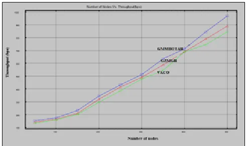
Throughput is measured in terms of bits per second (bps).In order to evaluate the throughput, the numbers of nodes in the range of 50-500 are taken in the simulation environment. When taking the 50 vehicle node, the 10KB of data packets are sent from the source to destination. By using GMMBOTAR technique, the destination node receives 152 bits per second whereas 132bits and 120bits are received using GZMGR and VACO technique. From the above-discussed results, it is clear that the throughput of GMMBOTAR technique gets enhanced than existing routing techniques.
Fig. 7. Performance Results of throughput
Fig. 7. shows the effects of the throughput with a number of vehicle nodes. As illustrated in the above Figure, the GMMBOTAR technique achieves higher throughput as compared to and VACO respectively. The optimization technique computes the fitness of all the vehicle nodes to find the best neighboring node and find the optimal route path to successfully deliver the data packets in a dynamic environment. This helps for GMMBOTAR technique to effectively deliver the data packets at the destination node without any loss as compared to other conventional routing techniques. The above results and discussion with different parametric results confirm that the proposed GMMBOTAR technique improves the performance of traffic-aware routing with higher delivery ratio, throughput and minimal normalized routing load, average end to end delay as well as collision rate.
6
C
ONCLUSIONINTERNATIONAL JOURNAL OF SCIENTIFIC & TECHNOLOGY RESEARCH VOLUME 8, ISSUE 09, SEPTEMBER 2019 ISSN 2277-8616 Finally, the route discovery is carried out between the vehicle
nodes by distributing the request and reply messages. Then the source node routes the data packets in a selected route path resulting in improving the data delivery and minimizing the delay. The simulation is performed with different performance metrics such as packet delivery ratio, average end to end delay, collision rate, normalized routing load and throughput with respect to a number of vehicle nodes. The observed result shows that the GMMBOTAR technique increases packet delivery and throughput with minimum delay, collision rate as well as normalized routing load. In summary, the proposed GMMBOTAR technique provides better performance and contributes towards a traffic-aware routing in VANET as compared to the existing techniques.
R
EFERENCES[1] H.Bello-Salau, A.M.Aibinu, Z.Wang, A.J.Onumanyi, E.N.Onwuka, J.J.Dukiya, ―An optimized routing algorithm for vehicle ad-hoc networks‖, Engineering Science and Technology, an International Journal, Elsevier, 2019, Pages 1-13
[2] Yusor Rafid Bahar Al-MayoufEmail authorNor Fadzilah AbdullahMahamod IsmailSalih M. Al-QaraawiOmar Adil MahdiSuleman Khan, ―Evaluation of efficient vehicular ad hoc networks based on a maximum distance routing algorithm‖, EURASIP Journal on Wireless Communications and Networking, Springer, Volume 265, 2016, Pages 1-11
[3] Chen Chen, Yanan Jin, Qingqi Pei, Ning Zhang, ―A connectivity-aware intersection-based routing in VANETs‖, EURASIP Journal on Wireless Communications and Networking, Springer, Volume 42, 2014, Pages 1-16
[4] Guangyu Li , Lila Boukhatem , Jinsong Wu, ―Adaptive Quality-of-Service-Based Routing for Vehicular Ad Hoc Networks With Ant Colony Optimization‖, IEEE Transactions on Vehicular Technology , Volume 66 , Issue 4 2017, Pages 3249 – 3264
[5] Nori M. Al-Kharasani , Zuriati Ahmad Zulkarnain, Shamala Subramaniam and Zurina Mohd Hanapi, ―An Efficient Framework Model for Optimizing Routing Performance in VANETs‖, Sensors, Volume 18, 2018, Pages 1-21
[6] Haitao Xu , Pan Pu , and Feng Duan, ―A Hybrid Ant Colony Optimization for Dynamic Multidepot Vehicle Routing Problem‖, Discrete Dynamics in Nature and Society, Hindawi, Volume 2018, September 2018, Pages 1-10
[7] Giuseppe Vitello , Alfonso Alongi ,Vincenzo Conti , Salvatore Vitabile, ―A Bio-Inspired Cognitive Agent for Autonomous Urban Vehicles Routing Optimization‖, IEEE Transactions on Cognitive and Developmental Systems , Volume 9 , Issue 1 , 2017, Pages: 5 – 15
[8] Mukund B.Wagh and N.Gomathi, ―Route discovery for vehicular ad hoc networks using modified lion algorithm‖, Alexandria Engineering Journal, Elsevier, Volume 57, Issue 4, 2018, Pages 3075-3087
[9] R.Brendha and V. Sinthu Janita Prakash, ―Geographical Zone Clustered Multi-Objective Glowworm Swarm Optimization for Routing In VANET‖, International
Journal of Computer Sciences and Engineering, Volume 7, Issue 5, 2019, Pages 965-975
[10]Forough Goudarzi , Hamid Asgari , Hamed S. Al-Raweshidy, ―Traffic-Aware VANET Routing for City Environments-A Protocol Based on Ant Colony Optimization‖, IEEE Systems Journal , Volume 13 , Issue 1 , 2019 , Pages 571 – 581
[11] Deepak Rewadkar and Dharmpal Doye‖, ―FGWSO‐TAR: Fractional glowworm swarm optimization for traffic aware routing in urban VANET‖, Wiley, Volume31, Issue1, 2018, Pages 1-22
[12]Taqwa O. Fahad and Abduladhem A. Ali, ―Multiobjective Optimized Routing Protocol for VANETs‖, Advances in Fuzzy Systems, Hindawi, Volume 2018, December 2018, Pages 1-10
[13]Yusor Rafid Bahar Al-, Nor Fadzilah Abdullah , Omar Adil Mahdi ,Suleman Khan , ―Real-Time Intersection-Based Segment Aware Routing Algorithm for Urban Vehicular Networks‖, IEEE Transactions on Intelligent Transportation Systems , Volume 19 , Issue 7 , 2018, Pages 2125 – 2141
[14]Yusor Rafid Bahar Al-Mayouf , Mahamod Ismail, Nor Fadzilah Abdullah, Ainuddin Wahid Abdul Wahab, Omar Adil Mahdi, Suleman Khan, Kim-Kwang Raymond Choo, ―Efficient and Stable Routing Algorithm Based on User Mobility and Node Density in Urban Vehicular Network‖, PLoS ONE, Volume 1, Issue 11, 2016, Pages 1-24
[15]Darwish, Tasneem SJ, Kamalrulnizam Abu Bakar, and Khalid Haseeb. "Reliable intersection-based traffic aware routing protocol for urban areas vehicular ad hoc networks." IEEE Intelligent Transportation Systems Magazine ,Volume 10, Issue 1 ,2018, Pages 60-73.
[16]Al-Mayouf, Yusor Rafid Bahar, et al. "Real-time intersection-based segment aware routing algorithm for urban vehicular networks." IEEE Transactions on Intelligent Transportation Systems, Volume 19, Issue 7 ,2018, Pages 2125-2141.
[17]Chun-Chih Lo and Yau-Hwang Kuom, ―Traffic-aware routing protocol with cooperative coverage-oriented information collection method for VANET‖, IET Communications, Volume 11, Issue 3, 2017, Pages 444 – 450