Seismic Analysis of Multi-Storeyed Buildings
with Shear Walls, Bracing and Openings
Mangala M M1, Dr. M D Vijayananda2
P.G. Student, Department of Civil Engineering, BIET, Davangere, Karnataka, Indiaˡ
Professor, Department of Civil Engineering, BIET, Davangere, Karnataka, India²
ABSTRACT: In the present study the effect obtained from the different positions placed in the bracingsand shear walls. The parameters for Seismic taken in to consideration are like such as storey displacement, storey drift ratio, storey shear, storey stiffness and time period which are considered to be found over the Response Spectrum Analysis under the consideration of the seismic Zone II as per taking in to the account of IS 1893-Part I (2002) which comes under main code guidelines.
Among all, the models with opening provided with shear walls and bracings are stable against seismic loads with lower storey displacement and storey drift ratio values. Further with high storey stiffness and storey shears. These also have shown lesser time periods. Thus making the structures stable against seismic forces.
KEYWORDS: Shear walls, Bracings, Openings, Response Spectrum Analysis (RSA), Storey displacement, Storey
drift ratio, Storey shear, Storey stiffness and Time period.
I. INTRODUCTION
An seismic vibration from the earthquake, huge amount of energy releases form the earth crust. While this energy is formed by a sudden crust and its segment dislocation of the man cause will be volcanic eruption or else it will be a manmade explosion. This dislocation of the crust causes huge destruction. Flow along the surface and at different velocities throughout the surface of the earth.
The opening considered in the Building to provide light and also ventilation along with the climate and its control considered also for rooms.
Here the considered RCC and the component of the structural walls will works in to avoid the lateral forces which will be formed by the wind. If we considered the thickness which will be of the shear walls it’s going to be vary from 150 mm to 400 mm. The main consideration Shear walls provides good performance stiffness and also as well as high strength to buildings at a particular direction and also optimum decrease in the lateral displacement which will be of the structures.
II. BUILDINGDESCRIPTION
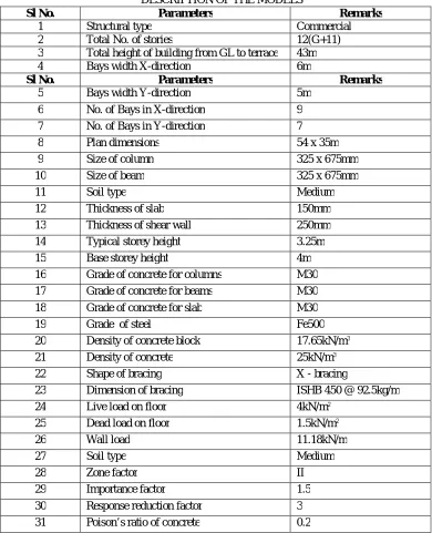
Table 1 shows the parameters and description of the developed models. TABLE I
DESCRIPTION OF THE MODELS
Sl No. Parameters Remarks
1 Structural type Commercial
2 Total No. of stories 12(G+11)
3 Total height of building from GL to terrace 43m
4 Bays width X-direction 6m
Sl No. Parameters Remarks
5 Bays width Y-direction 5m
6 No. of Bays in X-direction 9
7 No. of Bays in Y-direction 7
8 Plan dimensions 54 x 35m
9 Size of column 325 x 675mm
10 Size of beam 325 x 675mm
11 Soil type Medium
12 Thickness of slab 150mm
13 Thickness of shear wall 250mm
14 Typical storey height 3.25m
15 Base storey height 4m
16 Grade of concrete for columns M30
17 Grade of concrete for beams M30
18 Grade of concrete for slab M30
19 Grade of steel Fe500
20 Density of concrete block 17.65kN/m³
21 Density of concrete 25kN/m³
22 Shape of bracing X - bracing
23 Dimension of bracing ISHB 450 @ 92.5kg/m
24 Live load on floor 4kN/m²
25 Dead load on floor 1.5kN/m²
26 Wall load 11.18kN/m
27 Soil type Medium
28 Zone factor II
29 Importance factor 1.5
30 Response reduction factor 3
31 Poison’s ratio of concrete 0.2
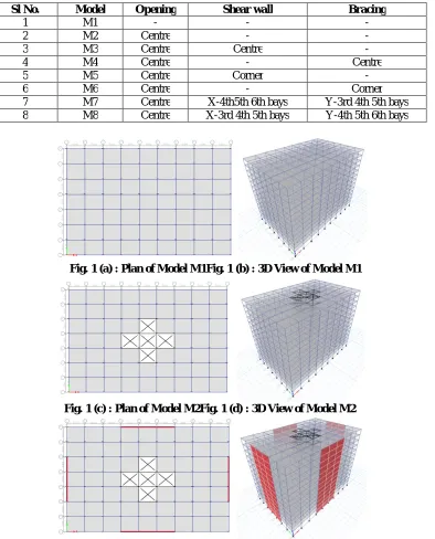
Sl No. Model Opening Shear wall Bracing
1 M1 - - -
2 M2 Centre - -
3 M3 Centre Centre -
4 M4 Centre - Centre
5 M5 Centre Corner -
6 M6 Centre - Corner
7 M7 Centre X-4th5th 6th bays Y-3rd 4th 5th bays 8 M8 Centre X-3rd 4th 5th bays Y-4th 5th 6th bays
Fig. 1 (a) : Plan of Model M1Fig. 1 (b) : 3D View of Model M1
Fig. 1 (c) : Plan of Model M2Fig. 1 (d) : 3D View of Model M2
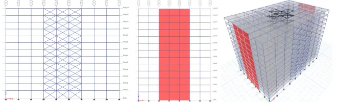
Fig. 1 (g) : Front plan of Model M4 Fig. 1 (h) : Side plan of Model M4 Fig. 1 (i) : 3D View of Model M4
Fig. 1 (j) : Plan of Model M5Fig. 1 (k) : 3D View of Model M5
Fig. 1 (l): Front plan of Model M6 Fig. 1 (m): Side plan of Model M6 Fig. 1 (n): 3D View of Model M6
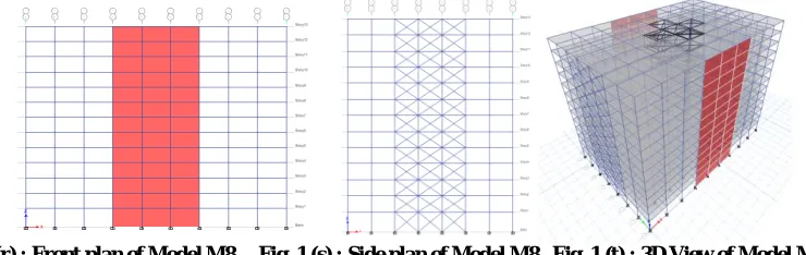
Fig. 1 (r) : Front plan of Model M8 Fig. 1 (s) : Side plan of Model M8 Fig. 1 (t) : 3D View of Model M8
Fig. 1 : Plan ,elevation and 3D view of all the developed RC building models with different position of shear walls and bracings.
III.SEISMICANALYSIS
The developed RC building models are subjected to Response Spectrum Analysis (RSA) as per IS 1893–Part 1 (2002) codal provisions. Different seismic parameters like storey displacement, storey drift ratio, storey shear, storey stiffness and time period are obtained from the analyses for all the developed building models.
IV.RESULTSANDDISCUSSION
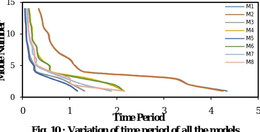
Figures 2 to 10 show the variation of storey displacement, storey drift ratio, storey shear, storey stiffness and time period over the number of storeys in X and Y directions obtained for all the RC building models by RSA.
Fig. 2 : Variation of storey displacement in X–direction Fig. 3 :Variation of storey displacement in Y-direction
Fig. 4 : Variation of storey drift ratio in X–direction Fig. 5 : Variation of storey drift ratio in Y–direction
0 5 10 15
0 50 100 150
S to r e y N u m b e r
Storey Displacement (mm) X-direction M1 M2 M3 M4 M5 M6 M7 M8 0 5 10 15
0 50 100 150 200 250
S to r e y N u m b e r
Storey Displacement (mm) Y-direction M1 M2 M3 M4 M5 M6 M7 M8 0 5 10 15
0 0.001 0.002 0.003 0.004 0.005 0.006
S to r e y N u m b e r
Storey Drift Ratio X-direction M1 M2 M3 M4 M5 M6 M7 M8 0 5 10 15
0 0.002 0.004 0.006 0.008 0.01
S to r e y N u m b e r
Fig. 6 : Variation of storey shear in X–direction Fig. 7 : Variation of storey shear in Y–direction
Fig. 8 : Variation of storey stiffness in X–direction Fig. 9 : Variation of storey stiffness in Y–direction
Fig. 10 : Variation of time period of all the models
From Figs. 2 to 10, it can be observed that all the models show different kind of variation w.r.t. storey displacement, storey drift ratio, storey shear and storey stiffness. However, similar kind of variation is exhibited from all the models w.r.t. time period.
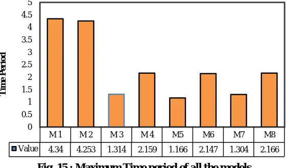
Figures 11 to 15 show the variation of maximum storey displacement, storey drift ratio, storey shear, storey stiffness and time period for all the buildingmodels by RSA.
0 5 10 15
0 10000 20000 30000 40000
S to r e y N u m b e r
Storey Sear kN Y-direction M1 M2 M3 M4 M5 M6 M7 M8 0 5 10 15
0 10000000 20000000 30000000
S to r e y N u m b e r
Storey Stiffness (kN/m) X-direction M1 M2 M3 M4 M5 M6 M7 M8 0 5 10 15
0 5000000 10000000 15000000 20000000
S to r e y N u m b e r
Storey Stiffness (kN/m) Y-direction M1 M2 M3 M4 M5 M6 M7 M8 0 5 10 15
0 1 2 3 4 5
M o d e N u m b e r Time Period M1 M2 M3 M4 M5 M6 M7 M8 0 5 10 15
0 10000 20000 30000 40000 50000
S to r e y N u m b e r
Fig. 11: Maximum storey displacement in X and Y Fig. 12 : Maximum storey drift ratio in X and Y Direction direction
Fig. 13 : Maximum storey shear in X and Y directions Fig. 14 : Maximum storey stiffness in X and Y directions
Fig. 15 : Maximum Time period of all the models
The Maximum values of storey displacement is observed in Model M1 than the other developed RC building models and least value of maximum displacement is observed in Model M5 in both X and Y direction is shown in Fig. 11.
M 1 M 2 M 3 M 4 M5 M6 M7 M8
X-Dir 140 138 53. 88. 48. 96. 89 52.
Y-Dir 203 195 65. 105 58. 113 65. 105
0 50 100 150 200 250 M a x im u m s to r e y d is p la c e m e n t (m m )
M 1 M 2 M 3 M 4 M5 M6 M7 M8
IS 189 3
X-Dir 0.00 0.00 0.00 0.00 0.00 0.00 0.00 0.00 0.00
Y-Dir 0.00 0.00 0.00 0.00 0.00 0.00 0.00 0.00 0.00 0 0.001 0.002 0.003 0.004 0.005 0.006 0.007 0.008 0.009 M a x im u m s to r e y d r ift r a ti o
M 1 M 2 M 3 M 4 M5 M6 M7 M8
X-Dir 153 146 379 241 409 207 244 373
Y-Dir 134 127 326 220 354 208 320 225 0 5000 10000 15000 20000 25000 30000 35000 40000 45000 S to r e y s h e a r (k N )
M 1 M 2 M 3 M 4 M5 M6 M7 M8
X-Dir 1E+0 1E+0 2E+0 4E+0 2E+0 3E+0 4E+0 4E+0
Y-Dir 5E+0 5E+0 1E+0 3E+0 2E+0 3E+0 1E+0 3E+0 0 5000000 10000000 15000000 20000000 25000000 30000000 S to r e y s ti ffn e ss (k N /m )
M 1 M 2 M 3 M 4 M5 M6 M7 M8
Value 4.34 4.253 1.314 2.159 1.166 2.147 1.304 2.166
The Maximum storey drift ratio obtained from all models except Model M1 and M2 are within the maximum allowable limit as specified by Cl. 7.11.1 of IS 1893–Part 1 (2002). Further, Model M5 in X and Y direction show minimum value of drift ratio value than the other considered models is shown in Fig. 12.
The Maximum values of storey shear is observed in Model M5 than the other developed RC building models and least value of maximum storey shear is observed in Model M2 in both X and Y direction is shown in Fig. 13.
The Maximum value of storey stiffness is observed in Model M5 than the other developed RC building models and least value of maximum storey shear is observed in Model M2 in both X and Y directions is shown in Fig.14.
The Maximum value of time period is observed in model M1 than the other developed RC building models and least value of maximum time period is observed in Model M5 is shown in Fig. 15.
V. CONCLUSION
In the present study, effect of different positions of bracings (X-bracing) and shear walls on performance of 11 storeyed RC building due to seismic is investigated using ETABS software (Version 2016). Seismic parameters such as storey displacement, storey drift ratio, storey shear, storey stiffness and time period are found out using Response Spectrum analysis (RSA) for seismic Zone II considering the stipulation laid down in IS 1893-Part I (2002) codal guidelines.
The important conclusions drawn from the present study are explained below considering the results obtained from RSA.
1. Different variation of displacement obtained from RSA over the number of storeys in X and Y directions for all the developed RC building models. However, displacements in X-direction are observed to be more than that in direction in M1, M2, M3, M4, M5, M6, and M8. Further model M7 displacement in Y-direction is observed to be more than that in X-Y-direction.
2. Different variation of storey drift ratio obtained from RSA over the number of storeys in both X and Y directions for all the developed RC building models. However, storey drift ratios in X-direction are observed to be more than that in Y-direction in M1, M2, M3, M4, M5, M6 and M8 models. Further model M7 storey drift ratio in Y-direction is observed to be more than that in X-direction.
3. Different variation of storey shear obtained from RSA over the number of storey in both X and Y directions for all the developed RC building models. However, storey shear in X-direction are observed to be more than that in direction in M1, M2, M3, M4, M5, M6 and M8 models. Further model M7 storey shear in Y-direction is observed to be more than that in X-Y-direction.
4. Different variation of storey stiffness obtained from RSA over the number of storeys in both X and Y directions for all the developed RC building models. However, storey stiffness in X-direction are observed to be more than that in Y-direction in M1, M2, M3, M4, M5, M6 and M8 models. Further model M7 storey stiffness in Y-direction is observed to be more than that in X- direction.
5. All models show similar kind of variation in case of time period for different modes of vibration Model M3 and M5 minimum value of displacement in X and Y directions respectively than the other considered models.
6. Maximum storey displacement is observed in Model M1 than the other developed RC building models and least value of maximum storey displacement is observed in Model M5 in both X and Y direction.
7. Maximum storey drift ratio obtained from all models except Model M1 and M2 are within the maximum allowable limit as specified by Cl. 7.11.1 of IS 1893–Part 1 (2002). Further, Model M5 in X-direction and M5 in Y-direction show minimum value of drift ratio value than the other considered models.
8. Maximum values of storey shear is observed in Model M5 than the other developed RC building models and least value of maximum storey shear is observed in Model M2 in both X and Y direction.
9. Maximum value of storey stiffness is observed in Model M5 than the other developed RC building models and least value of maximum storey shear is observed in Model M2 in both X and Y directions.
Concluding remarks: Among all, the models with opening provided with shear walls and bracings are stable against seismic loads with lower storey displacement and storey drift ratio values. Further with high storey stiffness and storey shears. These also have shown lesser time periods Thereby making the structures to be safe against seismic forces.
REFERENCES
1. Phadnis.P.Pand Kulkarni.D.K “Seismic analysis of multi storeyed RCC building with shear wall” National Conference on Research and
Development in Structural Engineering, pp. 133-141,(2013).
2. Madan.S.K.,Malik.R.S and Segal.V.K “Seismic evaluation with shear walls and braces for buildings” World Academy of Science, Engineering
and Technology, Vol 9, No. 2, pp.185-188, (2015) .
3. Grishma M. Patel and Hardik J. Solanki “Comparative seismic performance and evaluation of X-Bracing and Off-diagonal Bracing systems in
RC Buildings” National Conference on Recent Research & Development in core in Disciplines of Engineering, pp. 91-95,(2017) .
4. Anusha K and Raghu K “Analysis of Braced Frame Multi storied Structure with different angels as Per Indian Standards” International journal
of Research in Engineering and Technology, Vol 05, No 05, pp. 1816-1818, (2018).
5. Mahdi hosseini, Ahmed Najm Abdullah Al-Askari (2018) “Dynamic Analysis of Multi-Storey Building with Openings in Shear Wall”
International Journal of Engineering Trends in Engineering and Development Vol 5, No 8,(2018) .
6. Tejaswini M L and Sandhyarani“Seismic Behaviour and Pushover Analysis of Irregular Flat Slab Building with Different Lateral Resisting
Systems” International Research Journal of Engineering and Technology,Vol 05, No 06, pp.910-920,(2018) .
7. IS 456 (2000), “Plain and Reinforced Concrete–Code of Practice”, Bureau of Indian Standards, New Delhi, India.
8. IS 875–Part 1 (1987), “Code of Practice for Design Loads (Other than Earthquake) for Buildings and Structures. Part 1 Dead Loads – Unit
Weights of Building Materials and Stored Materials”, Bureau of Indian Standards, New Delhi, India.
9. IS 875–Part 2 (1987), “Code of Practice for Design Loads (Other than Earthquake) for Buildings and Structures. Part 2 Imposed Loads”,
Bureau of Indian Standards, New Delhi, India.
10. IS 1893–Part 1 (2002), “Criteria for Earthquake Resistant Design of Structures. Part 1–General Provisions and Buildings”, Bureau of Indian